Wrap Up
Session Start End
-
Brad Palmer (ConocoPhillips)
We have three CCRs with vent gas scrubbers; all are carbon steel, and all have experienced corrosion problems.
Fouling in the scrubber vessels and in the vent-gas lines has been severe and caused under-deposit corrosion in these areas. Corrosion in the scrubber vessel has included pitting of the walls, bottom head and thinning of nozzles. Thin spots in these vessels have been built back up and nozzles replaced as necessary. Corrosion of internals has been severe, including distributors, trays, demister pads and off-gas lines. Internal piping, equipment and vent-gas lines have been replaced.
Responses to the corrosion have primarily been mechanical. One unit has sand blasted their scrubber tower and coated the walls and bottom head with Belzona; the next turnaround will reveal whether this has been effective. One unit has changed metallurgy of their weld overlay and upgraded their demister metallurgy. One venturi scrubber has been upgraded to Hastelloy C-2000. The only operational change has been to increase the scrubber purge rate to reduce solids and salt concentrations.
Michael Windham (UOP)
The reactions taking place in the venturi scrubber/VGWT are as follows:
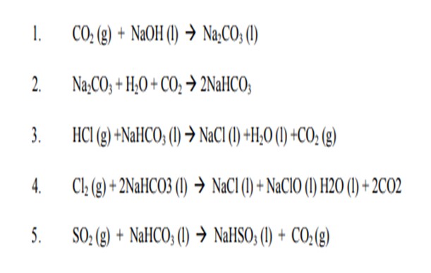
We learned from the past:
-There are two problems that can occur. One problem is if there is too much build-up of Na2CO3 and NaHCO3 due to too much caustic being injected and/or not enough draw-off, the Na2CO3 and/or NaHCO3 will precipitate out of solution and begin to cause plugging. The other problem is if there is insufficient Na2CO3 or NaHCO3 due to not enough caustic being injected and/or too much draw-off, there will be insufficient Na2CO3 and/or NaHCO3 to react with the HCl, Cl2 and SO2 in the vent gas then we have corrosion.
-Some unit claims they follow our guidelines for operation of VGWT but still they have corrosion. There might be other reasons to contribute to fouling and corrosion of the scrubber and downstream piping:
1-The vent gas enters the scrubber at ~450o C (842 oF) but the temperature of the caustic is ~40 oC (104o F). The caustic can get vaporized by the hot vent gas, resulting in the formation of the sodium salts (fouling) in the scrubber. (This has not been confirmed yet).
2-Sudden changes in the regeneration tower operation may contribute to formation of the salt. (Example: If amount of the Chlorides in the vent gas to the VGWT were suddenly increased or decreased, or temperature of the vent gas suddenly changed because of high coke). ( Not confirmed yet).
Which equipment (Venturi scrubber, wash tower) and piping have corroded more often?
The extent of the problem varies from unit to unit. In general, some of the units experience some type of plugging and corrosion every 6 months. In one case the unit has been in operation for slightly less than 2 years and is already on their 5th venture scrubber. The plugging (fouling) and corrosion of Venturi Scrubber and the line downstream of the Venturi Scrubber to bottom of Vent Gas Wash tower occurs more often since the majority of the acid neutralization occurs in the Venturi Scrubber
Erik Myers (Valero)
Valero has experienced similar corrosion challenges with this type of treating.
Ujjal Roy (Indian Oil Corporation)
We have four CCR/Platformers in our refineries. While two operates for gasoline production, one operates in mix mode i.e., for BT as well as for gasoline production. The other solely operates for para-xylene production.
We have experienced regenerator outage on many occasions from few hours to as high as 6-7 days. Moisture content in recycle gas is normally between 15 to 35 ppm in all these units when regenerators are under operation. During regenerator outage, even for longer duration, we never had to resort to water injection. At the most, we observe moisture reduction in recycle gas is by about 5 ppm from normal operation. As soon as regenerator is out of line, we immediately start chloride dosing in feed and closely monitor recycle gas moisture and chloride content. HCl in recycle gas is maintained at normal operating level.
In addition to proper water/chloride balance, we take various other actions to ensure limiting coke on catalyst within design level of regenerator capacity (which is generally designed for 6% wt. max. coke on spent catalyst). These actions are as below:
a) In one of our gasoline mode platformers, feed contains about 40% of FCC gasoline. We minimize FCC cracked gasoline in feed by optimizing FCC operation. Cracked naphtha coking rate is almost 1.5 times as compared to that of straight-run naphtha.
b) We reduce platformer throughput and RIT but also try to change the crude mix to get higher N+2A in order to get desired conversion and target RON. This may require costlier low sulphur crude processing as in our case is Bombay High. Gasoline production is partly made up by higher back blending of desulphurized straight-run naphtha having higher base RON.
c) With reduction in Platformer throughput, we also resort to increasing separator pressure and recycle ratio in order to get higher partial pressure of hydrogen by about 10-20% within available cushion of the equipment's. This helps in containing coke build-up during longer regenerator shutdown and sustain stable operation.
With all these measures, we have observed that the coke build-up rate on catalyst is about 0.25 – 0.3 wt.% of catalyst per day. At this rate of coke build-up, it helped us to continue operation without regenerator for as long as 7-8 days. When we started the regenerator back, we found that coke on the spent catalyst was about 6% wt. as against 4% wt. when the regenerator was shutdown. In one such occasion, in one of the platformers, the coke on spent the catalyst went up to as high as 10% presumably due to inappropriate control. Normally chloride on spent catalyst at the point of starting back the regenerator was found mostly between 0.9 – 1%.
When regenerator is out for a longer period, it is utmost important to control the coke laydown within the capability of regenerator design. High coke on catalyst may lead to slippage of coke to oxychlorination zone when the regenerator is started. It can also lead to high burning delta temperature. This in turn can change phase of the catalyst from gamma to inactive alpha alumina and permanently damages the catalyst. This happened in one of our refineries in a particular instance, when coke laydown was significantly high as compared to maximum recommended value resulting in presence of alpha alumina in regenerated catalyst after start of regenerator. In such circumstances, when regenerator is started back, coke burning rate to be kept well within design to avoid permanent catalyst damage.
In case, water is injected (that we have never done in any reformer) along with chloride in feed during regenerator outage, continuous monitoring of moisture and HCl in recycle gas should be done to ensure proper dosing control. High chloride will lead to excessive cracking. Also, if the catalyst is old and have considerable reduced surface area, chloride retention on the catalyst will be lower. Any excess chloride thus would land up in recycle gas. This can lead to corrosion related problems in downstream equipment and units.
Also, with increased chlorine retention on catalyst, activity of the catalyst increases while selectivity decreases. Hence, one has to optimize dosing based on the yields of desired products and conversion which is already affected by higher coke make when regenerator is down.
Some catalyst vendors offer high stability catalysts which tend to form lower coke at given conditions. If one is operating platformer without regenerator frequently, he can look for such catalyst in next replacement. But also new catalysts with higher surface area will make higher coke initially.
I would also suggest that during regenerator shutdown, delta T across reactors should be in focus along with parameters like H2 yield and purity, C3 – C4 yields. Feed blend, throughputs and severity should be properly managed based on these parameters. In all our refineries, naphtha and gasoline production are optimized through varying operation of hydrotreaters, reformers, isomerization, bensat and treatment units. These give us flexibility for feed management of both intermediate and finished products blending streams.
Olivier Le-Coz (Axens)
For a very short period of time (less than one day), there is no need to inject chlorinating agent with the feed to maintain the chlorine level on the catalyst.
For longer periods, chlorinating agent shall be injected (at about 0.4 wtppm in the feed) to maintain as close as possible to 1 wt% of chloride on the catalyst. HCl content in the recycle gas shall be carefully monitored and be maintained below 3 vol ppm. Water injection with the feed must be adjusted to maintain 20 vol ppm of moisture in the recycle gas. This moisture level is needed to ensure good chlorine spreading over all the reactors (and not only in the first one) by establishing proper H2O / HCl equilibrium and preventing local HCl excess. This will also allow minimizing cracking activity. Depending on the coke make, WAIT / catalyst circulation rate / H2/HC ratio should be adjusted to maintain the coke yield on the catalyst within the suitable range for the regenerator to be able to operate properly once this section is restarted.
Michael Windham (UOP)
When the CCR is shut down for more than a few hours, UOP recommends injecting chloride agent into the feed. Injection rates are generally in the 1.0 ppmw based on feed rate. Water injection is not normally required. For extended down time, operators should monitor reactor delta temperatures and adjust reactor temperatures or feed rate if the dT, s and reformate octane are declining.
Erik Myers (Valero)
In general, a significant maintenance downtime (7 days) would require the addition of chloride into the Reforming unit feed. Valero does not usually add water to the CCR unit feed. What may not be realized is the chloride uptake of the catalyst declines as the surface area decreases. In general, the chloride injection target, calculated as wt ppm chloride injected in the feed, needs to be increased over the life of the catalyst.
In a coke limited unit, feed should be cut to increase hydrogen to hydrocarbon and suppress coke lay down such that upon restart of the regenerator the coke is less than 7 wt%. Valero uses a 60% coke lay down distribution into the last reactor’s catalyst during periods of no catalyst circulation. The challenge is when to increase severity after restarting catalyst circulation and regeneration. Valero uses the following guidelines for reintroduction of full severity on the unit, once the last reactor catalyst is regenerated, 50% of the rate/octane cut is added back, when the catalyst from the second to last reactor is regenerated 30% of the rate/octane is added back and the last 20% of the severity is added back when the coke on catalyst goes below 6.5 wt%. In this manner the production of the CCR is maximized during the restart. Companies that do not model the reactor coke profile correctly will go from high coke to low coke in the course of the restart which has economic penalty.
Soni O. Oyekan, PhD (Marathon Petroleum Company)
The question is broad as the time involved in the low coke operation mode and the spent catalyst and regenerated catalyst chlorides before the outage of the regenerator are important factors. We can assess the delta chloride (regenerated catalyst chloride minus spent catalyst chloride) and use a trend of that data to assess the dryness of the reactor system. The dryness of reaction system can also be determined from the recycle gas water and HCl data for the catalytic reformer. Another factor is the relative state of the metal and acidic functionalities of the catalyst as a consequence of unsteady state cycling between black and white burn regenerator operations which could have negatively impacted platinum dispersion and the metal functionality.
While addition of water and chloride to the feed can give moderate boost in catalyst activity, there could be penalties associated with deceased productivity and poor selectivity as a consequence of excessive hydrocracking for the continuous catalyst regeneration reformer. However, the refiner could be limited with respect to proper water/chloride management, if the refiner has not established a good database on the performance of the catalyst in their reformer as a reference and simply adding water and chloride may actually be detrimental.
To make relevant, process enhancing water/chloride management moves requires that a good reference database of the reformer performance is available so as to permit comparing performance relative to reference as some of the water/chloride management steps are being made.
For short periods of regenerator outage, the refiner can assess or determine spent catalyst chloride levels and could add chloride if the expected levels are lower than catalyst chloride operating targets from experience. I would, however, not recommend adding water or chloride during short periods of outages for the regenerators of less than one day.
For longer periods, water/chloride management can be affected based on some knowledge of the items that I discussed earlier.
The items again are:
• Good reference data on catalyst performance during steady state white burn regenerator operations
• Good or reasonable information on metal and acid functionalities states of the catalyst via platinum dispersion and delta catalyst chloride data
• Reliable data on recycle gas water and hydrogen chloride.
A key consideration for water/chloride management steps when the regenerator is not operating is ensuring that the catalyst is not overloaded with chloride thereby exacerbating metal and acid functionalities imbalance which may have occurred due to the unsteady cycling of black and white burn regenerator operations.
Lastly, some considerations should be given to the effect of added water and chloride on potential increased fouling and corrosion in the product separation section (condensers, compressors, stabilizers) of the catalytic reformer. Additionally, the net hydrogen gas HCl could also increase, and suitable chloride guard systems should be in place to help manage the potentially higher HCl in the net hydrogen gas.
Praveen Gunaseelan (Vantage Point Consulting)
Nitrogen in naphtha feedstock can be detected using analyzers based on pyro chemiluminescence or electrochemical measurement. Pyro chemiluminescence-based analyzers appear to be more prevalent in the industry and can detect nitrogen levels over a wide range (from ppb levels to several hundred ppm) in a matter of minutes. ASTM D4629 is a standard test method for trace nitrogen detection in liquids based on pyro chemiluminescence.
As refiners increasingly process heavy crudes using cokers, the nitrogen content in naphtha feed to reformers will tend to increase. While conventional naphtha hydrotreaters can theoretically be operated at higher severity to increase nitrogen removal, there are practical limits on such operation due to potential undesirable outcomes, such as higher sulfur levels in the reformer feed due to recombination. Accordingly, preventing high nitrogen levels in reformer feeds may require specialized approaches such as using high-activity denitrification catalyst in a reactor section or a separate reactor. In extreme cases where nitrogen content is excessive and cannot be adequately removed, it may be required to limit the volume of coker naphtha processed in the reformer.
Ujjal Roy (Indian Oil Corporation)
In our refineries, ASTM D4629 is being mostly used for nitrogen detection. This method can detect 0.3 to 100 ppmw of total nitrogen with good reproducibility. Also, in some units, we are using licensors’ recommended test methods using their recommended apparatus for testing basic nitrogen.
Some naphtha hydrotreaters, having cracked material in feedstock, are designed to produce < 0.5 ppm nitrogen for feeding to reformers. Higher nitrogen level cannot be tolerated to avoid catalyst deactivation and downstream equipment fouling. These units are operated at about 50 kg/cm2 pressure using Ni-Mo catalyst. We are effectively able to control nitrogen within 0.5 ppmw in reformer feed.
Brad Palmer (ConocoPhillips)
The state-of-the-art in total nitrogen detection for naphtha and distillate streams is oxidative combustion with chemiluminescence detection. The standard test method for this technique is ASTM D4629-10. Direct injection of the sample into a vertically oriented combustion furnace will provide the best sensitivity. The reported quantitation limit for this technique is 300ppb.
Naphtha hydrotreaters are very effective at removing nitrogen IF:
1. Loaded with NiMo catalyst,
2. Catalyst replaced before denitrification reactions have stopped due to Si poisoning,
3. A proper water wash system is employed for salt removal upstream of the stripper,
4. Robust NH3 removal occurs in a reboiled stripper,
5. Nitrogen analyses on feed and product is done frequently with a low detection level
Erik Myers (Valero)
In general, Reforming units prefer low levels of nitrogen in the feed. The problem with nitrogen in the reforming feed is the deposition of salt in the cold sections of the reforming unit. Typical locations for salt deposit are cold areas of the recycle gas circuit and the top of the stabilizer system. Most naphtha hydrotreaters operate in a 300 to 700 psig range of design pressures. This means that sulfur removal is essentially 100% while nitrogen removal from the feed is seldom greater than 80%. Therefore, there is always nitrogen in the feed to the Reforming unit. Since the Reforming unit has abundant chloride present the rate of salt deposits is entirely dependent on nitrogen slip through the NHT unit.
At 0.5 ppm nitrogen in the feed each 10 mbpd will produce almost a ton per year of ammonium chloride. The ratio of chloride to nitrogen is 2.5 lbs of chloride to 1 lb. of nitrogen.
One best practice that Valero implements is to water wash the reformer recycle compressor when the unit is down to remove the salts that form during normal operation. This prevents imbalance from the sloughing off of salts that may take place during thermal cycles of the unit.
Soni O. Oyekan, PhD (Marathon Petroleum Company)
According to an analytical chemist, nitrogen determination in naphtha can be conducted via the use of an analytical procedure that incorporates an Antek Model 9000. The equipment is interfaced with an auto sampler and computer system containing an Antek 393 software. Nitrogen concentrations as low as 0.1 wppm and as high as hundreds wppm can be measured. Samples containing high nitrogen are diluted with isooctane before nitrogen determinations are made. Samples of isooctane blanks are also used as reference for zero nitrogen.
For the second part of the question, a key requirement is that the refiner has a good analytical procedure for determining nitrogen in hydrotreated naphtha and the response to the first part of this question addressed that challenge. Having established a reliable database and current hydrotreated product sulfur, nitrogen and other data, it is then possible to determine the effectiveness of a naphtha hydrotreater for nitrogen removal or reduction.
It is known that while 99.9 % hydrodesulfurization of organosulfur compounds can be achieved in naphtha hydrotreaters, hydrodenitrogenation (HDN) of organo nitrogen compounds is limited to the range of 75 % to 90 % conversion to ammonia. Therefore, the residual concentration of nitrogen compounds in hydrotreated naphtha is relatable to feed nitrogen and other factors.
The effectiveness of naphtha hydrotreating (NHT) for reducing nitrogen is highly dependent on the type of catalyst used, hydrodenitrogenation (HDN) activity of the catalyst, process conditions, concentration of metal contaminants in the feed, composition of the naphtha mix and the percentage of cracked naphtha in the naphtha mix and especially the percentage of coker naphtha in the NHT feed mix. Achievable HDN is also dependent on the degree of upgrading of naphtha from unconventional oils in the feed mix to the NHT. In addition, naphtha processing schemes are also important for the effective removal of nitrogen for straight run naphtha and especially for naphtha mixes containing other contaminants such as metals, olefins and dioolefins.
For modest concentrations of nitrogen of <2 wppm in the feed to the NHT and negligible concentrations of metal contaminants such as arsenic and silicon, the processing of the naphtha leads to hydrotreated naphtha with nitrogen in the range of 0.1 wppm to 0.5 wppm. For NHT naphtha feed containing high percentages of cracked naphtha (such as coker naphtha) and high concentrations of contaminants such as olefins, diolefins, arsenic and silicon, HDN could be limited if the concentration of organo nitrogen compounds are higher than 2 wppm with respect to meeting target nitrogen in the hydrotreated naphtha for the refiner.
The following factors are relevant for effective reduction of nitrogen in hydrotreated naphtha
1. Catalyst
For optimizing HDN, NiMo catalysts are usually preferred relative to CoMo catalysts Single reactors, moderate pressures, high quality treat gas and rates, reactor temperatures in the range of 500 to 615 F are used and the high temperature is usually limited by mercaptan reversion reactions. As the organo nitrogen compounds increase as well as other contaminants such arsenic and silicon, stacked catalysts are used in reactors to incorporate demetalization catalysts or metals scavengers to manage metal contaminants that can negatively impact HDN relative to HDS. In order to optimize organo nitrogen reductions, refiners should work closely with technology providers who offer a variety of catalysts and adsorbents for enhancing the effectiveness of the naphtha hydrotreating process for HDS and HDN.
2. Naphtha Processing Schemes
As the concentrations of nitrogen and other contaminants increase in mix naphtha feeds, refiners processing schemes include medium and high pressure stacked reactors, and multi stages of reactors (two and three reactors) to manage unsaturated compounds and metal contaminants in order to enhance HDN of the naphtha. Several catalysts are then used for effective reduction of organo nitrogen and other contaminants metals, sulfur, olefins and diolefins. As indicated, your technology provider companies will be pleased to support your efforts and plans.
3. NHT Stripper
As part of the reference database, the NHT stripper operations should be checked and determined to be operating as designed. Upsets in the NHT Stripper would also falsely suggest ineffective naphtha hydrotreating and high nitrogen (NH3) in the hydrotreated naphtha and in those cases high sulfur (H2S) and possibly water would also be carried into the catalytic reformer.
Michael Windham (UOP)
Whether or not methanol or another hydroxyl in injected into the oxy-Chlorination zone is based on the design of the regenerator. UOP designed units do not inject hydroxyls into the oxy-Chlorination zone, UOP recommends you contact the process Licensor before making any alternations to the Regeneration Tower flows or controls.
There are two primary objectives of the oxy-Chlorination: metals dispersion and obtaining the target chloride on catalyst. When methanol is injected into the oxy-Chlorination, a higher organic chloride rate is required to obtain the target chloride on catalyst; consequently, a higher chloride agent injection rate is required.
Injecting methanol into the oxy-Chlorination zone was originally patented by UOP in 1971, but not used commercially. UOP designs the burn zone to have a high Cl/Cl2 concentration, resulting in minimal metal agglomeration in the burn zone. Consequently, because of minimal metal agglomeration, water injection into the oxy-Chlorination was not required. The minimal metal agglomeration in UOP’s burn zone is exemplified by high H2/Pt with fresh catalyst in black burn operation (i.e., no oxychlorination).
Operational issues with injecting water are less flexibility in optimizing chloride on catalyst from the regenerator, since two targets are trying to be achieved. A higher chloride on catalyst may result in higher cracking and lower yields. Injecting water also increases the catalyst drying requirement. Also, depending upon the flow scheme, higher methanol injection rate could result in higher corrosion. Consequently, with the UOP’s high chlorine in the burn zone, optimal metals dispersion is obtained, operational flexibility, maintaining optimal yields.
Olivier Le-Coz (Axens)
The relevance or necessity of injecting alcohols in the oxy-chlorination zone depends on the conditions in the upstream burning zone of the regenerator and how this zone is designed. The facility to inject alcohols in the oxy-chlorination zone is foreseen in Axens design. Even without the dedicated line, it is still possible to inject alcohols by diluting them with the chlorinating agent and use the dedicated injection line provided the pump capacity is sufficient.
In Axens design water or hydroxyl generating compounds injection to this zone allows better controlling of the Delta chloride which is achieved in the regenerator of the CCR. Sufficient chlorine injection in the oxy-chlorination zone is essential to ensure good Platinum re-dispersion, but the total resulting chloride content on the alumina support must not exceed an optimum value. Too high chloride would enhance the catalyst acidity too much resulting in increased activity but non optimal selectivity towards reformate product. The chloride content on the catalyst depends on the equilibrium between water and HCl bonding on the catalyst support which is related to the ratio between water and HCl in the gas phase surrounding the catalyst. Injection of water or alcohol in the oxy-chlorination zone allows better control of this optimum ratio.
Erik Myers (Valero) This is more of a licensor specific item. We have one such unit and the unit operates well with the prescribed use of methanol in the chlorination zone.
Brad Palmer (ConocoPhillips)
ConocoPhillips does not add hydroxyl generating compounds to our CCR chlorination zone nor to the feed. There is enough moisture in the recycle streams to keep a good water/chloride balance on the catalyst. Adjusting the PERC injection rate is sufficient to maintain the correct chloride levels.
Jeff Lewellen (HollyFrontier)
We are currently constructing two new delayed coker heaters at our El Dorado, Kansas facility. As part of this project, we have performed both a process hazard analysis (PHA) and a safety integrity level (SIL) evaluation. We incorporated experience from other recent heater installations during these evaluations. However, unique differences were noted during these evaluations including:
• Heater tube fouling rates commonly resulting in tube skin temperature increases of 1o F to 4o F per day.
• Higher frequency of loss of process flow incidents
• Daily/hourly changes in heater conditions due to drum cycle impacts
• On line heater pass decoking – spalling
• Frequent off line heater pass decoking – steam air decoking/pigging.
• Bringing a heater off line or restarting a heater while the balance of the unit remains running.
• Multiple velocity steam injection locations into the process coils. However, this is common with other “heavy oil” units.
• Double fired coils utilizing shared burner rows with individual pass controls.
• Extended loss of charge heater firing resulting with incomplete coking of the residuum/asphalt in the coke drum.
With the analysis teams consisting of instrumentation/controls, operations, maintenance, engineering, and outside experts discussing these issues, a better design has evolved. Some of the key issues found through these evaluations include:
• As with all of the facility’s heater designs – the teams utilized API Recommended Practices for Fired Heaters 556 and ANSI/ISA-84.00.01 with good engineering practices to implemented adequate instrumentation and controls to maintain safe operation of the heater.
• Ensure adequate equipment and administrative systems are in place to test SIS to maintain reliability.
• Considered the controls and SIS for all of the operation and startup/shutdown modes. This included spalling, steam-air decoking, and shutdown/startup of heater with the unit online or offline.
• Evaluated best practice instrumentation in the design, level of redundancy, and control technologies to optimize for both shutdown and inadvertent heater trip situations.
• When the heater is shut down by the SIS, insured equipment is designed to help the operator quickly recognize the trip has occurred, understand the cause of the trip, correct the condition, and restart the heater if safe to do so. This includes o Utilize Instrumentation/alarm prioritization for “first out” information.
o Facility design and logical location of HMI panels to aid in operator response.
o Complete and detailed operator and maintenance training on these systems.
o an adequate administrative system (including levels of authority) to implement “By-Pass” of the SIS and/or DCS in the event of a malfunction or for maintenance of system.
• Evaluated operating procedures and equipment is in place to safely address the consequences of a heater trip that cannot or should not be restarted those results in a un-coked residuum (tar ball) event.
Gary Gianzon (Marathon Petroleum Company)
The coker heater is unique since a loss of heat or heater shutdown can result in an unconverted pitch “tar ball” in the drum which in itself creates its own hazard. That being said, MPC’s SIS philosophy is to get the heater in the safe state and address the “tar ball” issue through our emergency procedure.
The flame of the low duty burners used in the coker heater can be hard to detect and have caused unnecessary heater trips. This issue was remedied by using a combination of flame rods and flame scanners to prevent spurious shutdowns or trips. We also have emergency steam automatically activated on low pass flow to prevent the heater tubes from plugging which is unique to the coker furnace SIS.
Rajkumar Ghosh (Indian Oil Corporation)
After a Coke drum is taken offline, it is steam stripped with ‘little’ steam @ 2.5 t/hr for 30 minutes (28 ft drum) to main fractionator to recover volatile hydrocarbon material. During this period, following conditions exist in the offline coke drum:
a. As the coke drum is filled to near its maximum allowable level, there is less vapor space available in the drum.
b. Presence of 8 – 10 ft high foam front
c. Reduced system pressure, as the fresh coke drum is yet to achieve its normal Coke drum outlet temperatures
Under these conditions, sudden drop in pressure of the off-line Coke drum results in re-foaming phenomenon. This can happen due to:
a. Switch over being done to a relatively cold Coke drum. Because of the changeover at a lower temperature and very less vapour generation, the overall system pressure comes down till the fresh Coke drum has achieved the overhead temperature of at least 420o C.
b. Very quick changeover in less than 30 minutes in a Coker having 4 or less drums would result in lower system pressure immediately after switching over.
c. If there is condensate carryover into the Coke drum along with ‘little’ steam, it results in immediate pressure surge and subsequent abrupt lowering of pressure. This also enhances chances of refoaming.
The steps taken at our cokers to minimize re-foaming while steaming to the fractionators are:
a. Proper heating of the drum is ensured to avoid switching to the cold drum. We monitor the Coke
drum Skin temperatures and our standard is to maintain these temperatures in the range of 260 –
280 degrees C
b. Condensate draining is done religiously prior to putting in steam to the offline coke drum.
c. The quantity of steam being put into the Coke Drum, to be done in-line with Licensors’. recommendations or based on firm procedures based on experience. Lower steam rate can cause faster rate of pressure decline in the drum and also blockage of channels in the coke bed while higher steam rate can lift the foam front of the filled drum towards fractionator.
d. Antifoam injection is started approx. 4 hrs before switchover and is continued in the off-line coke drum till it is lined up to blowdown. If frequent problems of refoaming are being faced, the rate of antifoam injection can be increased during switch over.
e. In case high system pressure drop is observed during and after the drum switch, we have a practice of increasing the set point for Wet Gas compressor suction pressure thereby reducing the RPM of Compressor.
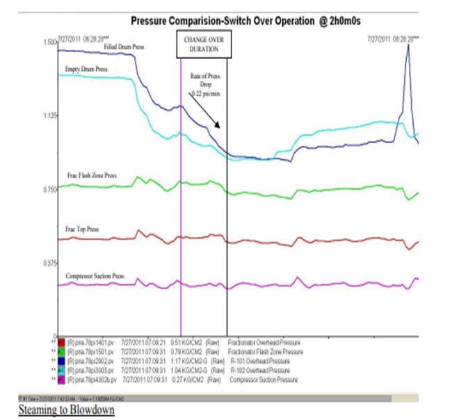
Generally, we ensure that rate of pressure fall in the offline coke drum is in the range of 0.22 to 0.25 psi/ min immediately after switching over. This ensures that refoaming doesn’t take place. (Trend of coke drum pressures during a typical switch over is attached)
Once steaming towards fractionator is over, the steam and residual vapour from the drum overhead is routed to the blowdown system and steaming is ramped up to 16-18 t/hr (28 ft Coke Drum) and continued for 1.0 hr. If this switch to blowdown is performed too fast, it might again cause a sudden pressure drop in the drum which might uplift the foam bed. In some instances, foam and other material have been sucked in the drum vapour line and caused severe fouling and plugging.
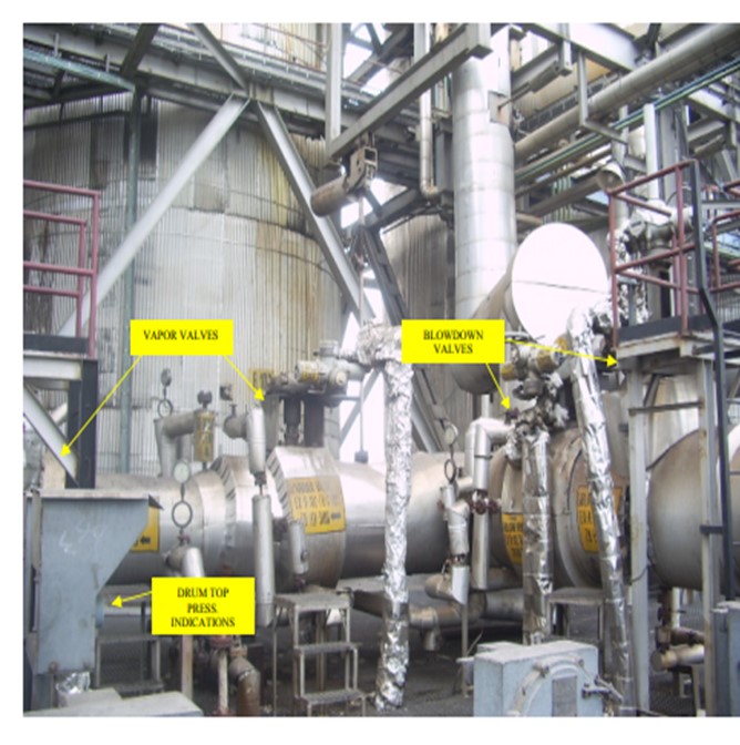
As there is a significant pressure difference between the offline drum (1.1 kg/cm2 g) and the blowdown system (0.3 kg/cm2 g), care is to be taken by the operator to perform the switch to the blowdown system smoothly. We advice our operators to fully close one of the Vapour valves prior to opening the Blowdown valve. Further, the blowdown valve opening is to be manipulated through ‘inching’ control for slowing depressurizing the Coke drum pressure to Blow down.
As a best practice, we have configured the layout of Vapour valves, Blowdown valves and the Coke Drum pressure local indication in such a way that the valves can be operated with an eye to the pressure indication.
Prediction for refoaming
Data for predicting refoaming tendencies based on Coker feed properties is not available with us. However, it’s understood that Coke drums experiencing the following aspects may end up having tendency to refoam :
a. Sharp variations in feed quality w.r.t. API gravity
b. Light oil ingress in Coker feed through slop route
Jeff Lewellen (HollyFrontier)
I concur with the primary answer, and would like to highlight two additional events when foaming can be a significant issue:
o Establishing steam (or re-establishing feed) to a drum following a charge heater upset may result in a sudden foaming event. Typically, this occurs following loss of charge heater firing, or during startup and shutdown activities.
o Our experience indicates heavier unit feeds allow us to operate at lower heater outlet and drum outlet temperatures while maintaining same coke qualities. However, the lower drum outlet temperature tends to form a shorter, denser, and more stable foam layer that is more difficult to collapse. Higher antifoam rates are required to prevent a foaming event.
Eberhard Lucke (Commonwealth E&C)
Foaming during the steam stripping step can occur for different reasons. The most typical mechanism I know of is foam entrainment when depressurizing the drum from fractionator to blowdown pressure. This can be controlled by the speed of depressurization (slow opening of blowdown valve). In general, to see foaming during the steam stripping step there has to be significant amount of hydrocarbon liquid sitting on top of the coke bed. Not going into all the details of what feed properties influence this behavior, all residues that coke relatively slowly (typically high aromatic coke content, low asphaltenic coke content) will leave more liquid on top of the coke bed after switching the coke drum. This liquid layer can foam up if for example the steam stripping flow rate is ramped up too fast, or if there is condensate entering the drum with the steam that spontaneously vaporizes and causes a peak in steam flow through the coke drum. One idea to think about: ramp up the coil outlet temperature for 15-30 minutes at the end of the drum cycle to boil off more of the liquid from the coke bed.
Tom Collins (Forum Energy Technologies)
Standard laboratory tests include salt, BS&W, gravity, viscosity, and filterable solids. The amount, and type of filterable solids can be the greatest factor to consider for interface emulsion resolution and predicting performance. Testing can be time consuming, and of little value without correlations to commercial desalter performance, so a database of crude types and properties is advantages. Typically blending of several crudes in a charge tank may offer little time to accurately predict performance, in which case the best tool is experience. Along with the standard analytical tests, during operation, volts & amps should be monitored, along with interface emulsion composition and effluent water quality, all of which can be used to predict desalter performance, and help establish a data base.
George Duggan (Baker Hughes)
We have worked with several refining organizations that process heavy Canadian crude oils to find the optimum desalter operating temperature. In general, raising temperature reduces the crude oil viscosity, which is desirable from a Stokes’ Law stand point as it makes breaking the emulsion easier. On the other hand, asphaltenes are destabilized by factors such as solvency, pH, and increasing temperature. In some crude blends, maximizing desalter temperature in an effort to improve oil-water separation has led to asphaltene destabilization, which contributes to emulsion band growth and negates the benefit of lower viscosity. The degree of asphaltene destabilization required to induce desalting problems is often less than that required to manifest itself as heat exchanger fouling. As mentioned on the previous question, our ASIT technology is used to gauge the relative potential for asphaltene instability in crude blending, both for desalting concerns and preheat fouling. Efforts to optimize desalter temperature have led to operating temperature targets to balance the needs for reducing viscosity with minimizing asphaltene instability effects. The customers who have gone this route consider the optimum temperature target confidential information, so we are not at liberty to share specific operating targets. For refiners who are unable to stay at or below the target temperature, we apply asphaltene stabilizer chemicals in the crude storage tanks to improve asphaltene stability and prevent desalter emulsion problems.