Question 9: What has been your experience with antimony and phosphorous poisoning on hydrotreating catalyst performance? What is the maximum level?
Kaspar Vogt (Albemarle) Antimony (Sb)
The effects of antimony in oil on hydrotreating catalyst have not been directly studied, but we can infer the likely impacts of antimony from a variety of information sources and past experiences.
As background, contaminant metals such as nickel can deposit on the FCC catalyst. This will result in increased dry gas (H2 in particular) and delta coke. Depending on the unit constraints this can lead to lower FCC conversion and lower feed rate. Many refiners use antimony in the FCC riser to passivate the detrimental effects of nickel. Antimony will cover the nickel enriched catalyst surface. Side effects are that the Sb will also cover the CO and NOx promoter metals and make these additives less effective.
Excess antimony mainly accumulates in the FCC slurry. However, antimony can be present in the heavier FCC products which are hydrotreated downstream. If the antimony enriched FCC catalyst fines are entrained into the hydrotreater, they can deposit in the catalyst interstices. This will impact bed pressure drop but not catalyst activity. The bed pressure drop build up can be managed by a guard bed catalyst system of sized and shaped catalysts to increase the void fraction and create more particulates capacity.
By analogy with the FCC experience, we would expect antimony in oil to preferentially coat nickel and cobalt promoter metals on the NiMo and CoMo catalysts. Ultimately, this would completely poison the catalyst. During the buildup of coating/poisoning, the activity will likely see a shift towards direct desulfurization (DDS) vs. indirect/aromatic saturation, thus the hydrogenation-to-hydrogenolysis ratio will change. A given concentration of Sb on catalyst would be expected to have a more severe effect on the catalyst performance in high severity HDS/HDN operations like ULSD and hydrocracker pretreat (HC-PT) service than in lower severity hydroprocessing applications such as NHT and LSD.
We seldom, if ever, detect antimony in the interior of spent hydrotreating catalysts where it would be expected to impact activity.
Furthermore, given its position in the periodic table, we would expect that Sb attacks the catalyst's active (NiMo and CoMo) sites, and that it would be a relatively severe poison, similar to arsenic (As), sodium (Na) and lead (Pb). Therefore, we would expect ≤1.0 wt% Sb would reduce HDN/HDS relative volumetric activity (RVA) by approximately 50% in non-severe applications, and that even lower Sb concentrations could severely reduce catalyst activity for high severity operations like ULSD and HC-PT.
Phosphorous (P)
Phosphorous (P) can come into the hydrotreater feed from:
- crudes
- drilling fluids
- phosphated ZSM
- phosphorous-based corrosion inhibitors and flow improvers
- phosphorous from solid phosphoric acid catalyst
-biofeeds
In catalyst manufacturing, phosphorous added on hydrotreating catalyst acts as a promoter and provides additional acidity to enhance HDN, hydrogenation and cracking reactions. Phosphorous also improves metals dispersion on the catalyst surface.
In one instance, we saw that 3 wt% of phosphorus on the catalyst terminated all the exotherm in bed, although other poisons where also present. Organic phosphorous can penetrate into catalyst pores. In general, our understanding is that the poisoning was similar to sodium where ~1.0 wt% concentration halves the catalyst activity.
In a separate instance, we found SiP coming from a solid phosphoric acid catalyst, used in certain FCC gasoline desulfurization processes with some iron deposited at the external surface of the catalyst extrudate. Some phosphorous and silicon also penetrated the catalyst pores. However after the first 0.1 mm, no contaminant phosphorous and silicon were found on a main bed CoMo catalyst. In this case, a layer of P-Si-Fe had deposited at the pore mouth and restricted the diffusion into the catalyst.
Photos of the outer surface including chemical composition are shown below. They show that Alumina, Molybdenum and Cobalt are homogeneously distributed within the catalyst particle, while phosphorous, silica and iron are located at the outer surface of the particle.
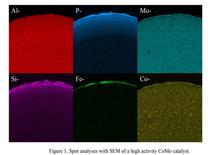
We observed that the Si & P from this process behaves totally differently from Si from anti-foaming agents. There are Si-P particles which cannot penetrate the internal pores of the catalyst and are deposited on the catalyst outer surface. The accumulation of these particles cannot be prevented. Therefore, sooner or later, bridges from particle to particle are formed, thus causing pressure drop buildup.
The bottom line is that the quantitative effects of phosphorous on hydroprocessing catalyst performance and the maximum allowable levels are highly dependent on the source and form of the phosphorous compound. It is also dependent on catalyst properties and the process application.
Martin Gonzalez (BP)
Phosphorus can sometimes be found in crude as alkyl phosphates added to passivate metals or protect against naphthenic acid corrosion. Phosphorus esters in crude may originate from waste oils, or from additives injected into wells to improve recovery. Some of the phosphorus may be in a form that volatilizes into distillate fractions bound for hydrotreaters. We have encountered some Canadian crudes containing phosphorus originating from fracturing fluids used in production. Phosphorus content in light sweet crudes seems to be declining, but it may be becoming more prominent in heavy crudes. There have been reports in the industry of ULSD units suffering catalyst deactivation as result of phosphorus from these crudes. From our experience, at 1 wt% on catalyst, it is reasonable to expect a 15-30% activity loss.
Charles Olsen (ART)
Phosphorous (P) contamination in oil has been traced to frac fluids that are often used in crudes from the Western Canadian Sedimentary Basin. The source is diphosphate esters which are soluble in the crude oil. Refineries that run large percentages of light Western Canadian crude have reported crude column and crude furnace fouling for many years. Improvements made to crude columns to minimize fouling have transitioned the depositing of phosphorous to the downstream hydrotreaters.
Other sources of phosphorous include gasoline slop tanks, imported feeds and lube oil wastes. If phosphorous does manage to make its way into the hydrotreater it will poison the active sites of the catalyst causing a loss in activity. A level of 1 wt% of phosphorous on the catalyst results in roughly 10°F loss in activity. ART recommends that a feed content of < 0.5 wppm be maintained whenever possible as well as the use of feed filters to assist in trapping of phosphorous sediment.
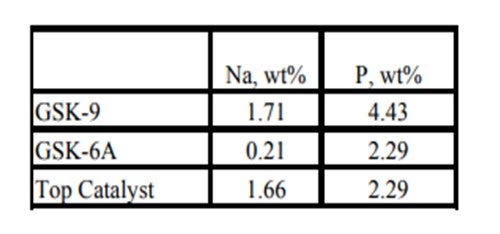
Historically, phosphorous contamination has not been very common, but with the increasing use of opportunity crudes it is being observed more frequently. A recent example is summarized in the table below shows the results of some spent catalyst analysis from a diesel unit. This unit experienced extremely rapid catalyst deactivation shortly after start up. It was so severe that within several months the unit required an unplanned turnaround and fresh catalyst was installed. The spent catalyst analysis indicates the catalysts were exposed to high levels of several poisons including sodium and phosphorous. The contaminants penetrated well into the catalyst bed. The level of contaminants indicates the catalyst in the top half of the bed had lost over 60°F of activity.
Year
2011
Process
Question 10: When replacing a noble metal catalyst with a base metal catalyst in a two-stage hydrocracking unit configuration, how can you be certain that under a low sulfur, low hydrogen sulfide environment, the second stage catalyst will remain sulfided?
Kaspar Vogt (Albemarle)
A base metal sulfide catalyst will always have less, or hydrogenation compared to a noble metal catalyst. However, in certain situations where deep hydrogenation is not needed, the base metal sulfide catalyst can provide adequate hydrogenation activity. Operation with a base metal catalyst will be between 10 to 20o F higher than a noble metal catalyst, and this will shift the yield towards more thermally cracked lighter products.
Due to the presence of platinum on the noble metal catalyst significant fill cost savings are achieved by loading base metal catalysts.
It would not be recommended to operate a base metal catalyst in a completely sweet service without the presence of H2S. The catalyst risks reduction of the metal sulfides, which will impact the activity and can permanently damage the catalyst.
Effective ways to get around the sulfur stripping of the base metal catalyst in an H2S free environment include spiking by DMDS injection, slipping of some sour gas from the 1st stage over to the 2nd stage, turning off the amine wash, and/or raising the hydrocarbon organic sulfur slip. H2S in the second stage recycle gas is in the range of 15 to 40 ppm to keep the catalyst sulfided.
For a standalone second stage reactor, another issue is corrosion. Since a typical sweet second stage does not have wash water injection, it is important to be careful of metallurgy, especially on the second stage air effluent coolers.
Year
2011
Process
Question 12: Is there any harm adding cracked stocks too quickly after break-in following catalyst activation? What is a typical introduction rate?
Tim Lewer (Shell)
On freshly activated catalysts, the surface is relatively clean (free of coke) and therefore is unusually active. This is sometimes referred to as hyperactivity. In order to maximize catalyst stability for good cycle length, it is important that the rate of coke lay down on freshly sulfided catalyst is gradually controlled. Upon completion of metals sulfiding, catalyst hyperactivity exists, but is short lived as feed processing lays initial coke on catalyst. Processing cracked stocks that contain more reactive molecules and coke precursors too early over the hyperactive catalyst can result in operability issues through cracking while accelerating the initial coke lay down on catalyst.
Cracked stocks contain large amounts of aromatics and olefins, which release large amounts of heat when saturated. Aromatics and olefins undergo saturation, but they can also condense or polymerize to form larger molecules, gums, and coke. When cracked stocks are introduced too soon, passing such highly reactive molecules over hyperactive catalysts leads to excessively high reaction rates. The resulting high exotherms aggravate the situation, because reactions like polymerization are faster at higher temperatures. By processing only straight run feeds for the first 72 hours after catalyst activation, the initial coke lay down is gradual for improved long-term stability.
The cracked stock introduction rate varies by unit, but should allow for exotherm stabilization, reestablishment of unit pressure as H2 consumption increases, and coordinated with smaller temperature additions to treat the more reactive feed molecules.
Minh Dimas (CITGO)
I understand “break-in” to be the same as “catalyst conditioning period” – i.e., three days of straight run material only (no cracked stock). It is imperative to adhere to the three full days of break-in (or catalyst conditioning) period following the catalyst activation/sulfiding (which is not included in the three days). After the catalyst is successfully conditioned, the cracked feed can be introduced as quickly as desired by Engineering and Operations (comfort factor) and as manageable by the unit equipment and utilities (i.e., charge heater, hydrogen makeup rate vs. consumption, reactor quench ability, etc.). Since the catalyst conditioning period “quenched” the hyper-active sites of the catalyst, the introduction rate of cracked material after the catalyst break-in / conditioning is negligible.
Kaspar Vogt (Albemarle)
Cracked and heavy feedstocks contain significant quantities of hydrogen deficient molecules known as “coke precursors”. These coke precursors (olefins, poly-nuclear aromatics, asphaltenes, concarbon) tend to polymerize, condense or form coke, given the right set of reaction conditions. Freshly sulfided catalyst, with little or no carbon deposits, is in an ultra-active state. Coke precursors in the feed readily react on the catalyst to produce a molecule with an extremely reactive free radical site. Ideally, this site would react with hydrogen but, because there are so many reactions taking place on the catalyst in its ultra-active state, there can be localized hydrogen deficiency. Without hydrogen readily available to react with the free radical site, the molecule may polymerize or condense with another active molecule, or it may simply deposit on the catalyst surface as coke. All of these outcomes result in blocked pores and/or active sites. Fresh catalyst has hyperactivity due to the absence of coke. Once coke has laid down, the catalyst reaches its design activity, and the coke prevents the agglomeration of metals.
Testing shows the loss of activity between immediate and a three-day waiting period before cracked feed introduction to be 10-15%. We recommend to stepwise increase the amount of cracked stock, which will have a higher exotherm, so that the unit does not incur large temperature swings. It varies per unit depending on the feeds and operating conditions but typically addition of 10% of cracked stocks per two-hour period is good operating practice.
There are commercial offerings available to ex-situ sulfide the catalyst with a special cracked feed protection (CFP) treatment for direct introduction of the cracked feed.
Ben Sim (ART)
Introducing cracked stocks too early after sulfiding will cause noticeable loss in activity. Coke precursor molecules in cracked feeds will have a tendency to form coke over the fresh and highly active sites on the catalyst. By delaying the introduction of cracked stocks for at least 3 days after sulfiding will allow the catalyst activity to be passivated which helps to minimize these effects.
After running for three days on straight run the cracked material should be added to the feed stream gradually. ART typically recommends adding the cracked feed in small increments every shift making sure the reactor exotherm remains under control and within acceptable limits before increasing the cracked feed amount any further.
Year
2011
Process
Question 13: What are your experiences with alternate procedures or additives to speed up the time to hydrocarbon-free a hydrotreater during cool down? What are potential downsides? Qualitatively, did the time savings justify the expense?
Martin Gonzalez (BP)
We have used a terpene-based product to help free hydrotreater reactor circuits of hydrocarbon in preparation for catalyst change-out. The product was effective for achieving a low level of combustibles in the reactor and in all vessels of the reactor circuit. However, in one instance, the test for entry indicated high benzene levels, and further nitrogen purging was required. As a result, the benefit of a quicker shut-down was not fully realized. In our trials, the greatest gains in shut-down duration resulted from the review and optimization of cool-down procedure that took place in preparation for the injection, rather than from injection of the chemical itself. Also, note that chemical may heat up the catalyst upon application, due to a relatively high heat of adsorption. Such a warmup may extend cool-down time beyond what was anticipated.
Tim Lewer (Shell)
Some plants have used additives during the hydrotreater reactor cool down period in order to remove hydrocarbon, especially benzene. These additives have been used with varied degrees of success. To this date, data has been inconclusive as to whether or not the chemical additive speeds up reactor decontamination versus conducting a proper hot hydrogen strip.
Injection of chemical additive requires several extra considerations in addition to the expense of the chemical:
• Waste disposal – Chemical suppliers may claim that their product is safe for refinery re-run systems, but most plants will be hesitant to re-run through the crude unit due to concerns, for example crude column overhead corrosion.
• Piping for injection – Temporary piping needs to be installed in order to inject chemical to the desired locations. This creates additional expense and maintenance workload during unit shutdown. Also, many plants may not allow connection to the process until the unit is down to a low enough pressure.
• Hold points – Many chemical additives need hold times at certain temperatures per the manufacturer to guarantee hydrocarbon removal. This will add time to your cool down.
Year
2011
Process
Question 14: Have you successfully dumped, screened and reloaded spent hydrotreating or hydrocracking catalyst without regeneration during a turnaround? Can you share any best practices during this operation to avoid problems on restart?
Kaspar Vogt (Albemarle)
We have experience with dumping, screening and reloading hydrotreating and hydrocracking catalyst. Here are two typical times this occurs:
1. After a full cycle – In these cases spent catalyst has been reused, without regeneration or reactivation, in a lower severity application for which the remaining activity is sufficient.
2. Early in the cycle – If at the start of the cycle the pressure drop is very high (due to, for example, broken inert balls or when significant maldistribution in the catalyst bed is measured), it can make sense to unload, screen and reload the catalyst.
Although it has been performed successfully, more often it has led to more pressure drop problems.
Best practices:
First, the safety aspects of handling a pyrophoric or self-heating material MUST be addressed. We believe it is critical to use proper detectors (SOX, H2S, etc.) and have proper emergency procedures and properly trained personnel in place before executing the catalyst dumping, screening and reloading process.
It is also important to dry the catalyst before unloading. Dust and small particles stick to the oily catalyst during dumping and screening and are not removed until liquid washing of the catalyst surface. This can lead to fouling of the catalyst bed and reactor internal trays and create excessive pressure drop at restart. H2 stripping to remove liquid between particles before unloading the catalyst is highly recommended.
It is important to split the different catalysts layers by either vacuum unloading guard and grading layers from the top or size screening after dumping in order to be able to reload a properly designed catalyst system.
If the screening is done on-site, we recommend the use of a relatively large screen to ensure broken fragments and small particles are rejected. This will prevent differential pressure issues with the reloaded material.
Providers of onsite screening services are typically limited in available equipment compared to offsite specialized companies. It is important to have adequate equipment to determine the particle size distribution of the screened catalyst. Evaluating the entire length distribution and not just the average length is a critical step for preventing excess pressure drop. It is also advisable to conduct a pressure drop test on the pilot scale to fully evaluate the effectiveness of the screening and predict the corresponding pressure drop for the screened catalyst load. Often some additional fresh guard, grading and main bed catalyst is needed to ensure a complete reactor fill.
Martin Gonzalez (BP)
Dump, screen, and re-load of spent hydrotreating catalyst are usually unattractive for various reasons. To minimize oxygen exposure, catalyst loading companies can usually keep screening equipment under inert atmosphere. Vacuuming catalyst rather than dumping can help to simplify screening by avoiding a mix of many sizes of material. Modern vacuuming equipment can also result in less breakage of catalyst, compared to gravity unloading.
Tim Lewer (Shell)
The practice of unloading, screening, and reloading still-viable hydrotreating or hydrocracking catalysts during turnarounds and without off-site regeneration has been done successfully – with catalyst vendor on-site support or project management. However, there are numerous factors involved in the decision to do so, especially with the advent of stacked bed catalyst schemes with multiple layers of materials either equal in size or too close in size to screen successfully using typical mobile equipment. For single bed hydrotreating reactors, which often contain a majority of same type/size catalysts, the task is more manageable but still a complex undertaking.
Extensive pre-planning is paramount to the success of this type of operation. There are a number of “best practices” that will help to ensure a successful outcome after the decision is made to re-load unregenerated catalysts versus loading fresh catalysts:
1) Research and hire a catalyst handling contractor that possesses the latest catalyst vacuuming/N2 recirculation, dust control, and screening equipment. All equipment used in such an endeavor must have the capability of being effectively purged with nitrogen.
2) Vacuuming support/grading layers from the tops and bottoms of beds and keeping these materials separate from main bed catalysts will allow for quicker screening rates and cause fewer losses due to breakage.
3) Ensure that there are excellent QA/QC measures in place, such as container labeling (where in the bed material is from, pre- and post-screened tare and net weights of all containers, etc.) and strict, written tracking and segregation of unscreened and screened containers.
4) It is imperative to establish clear guidelines prior to the start of the project to ascertain what properties need to be met in order for screened catalysts to be acceptable for reloading. These guidelines should include acceptable levels of fines, average catalyst length, and acceptable levels of cross contamination between different catalyst types and/or sizes. Screen sizes and opening shapes (slotted or square), controlled rates and constant oversight by personnel aware of the established guidelines and desired outcomes of the screening operation are critical to a successful end product.
5) Consult with your catalyst supplier to arrange for lab testing of unloaded materials to ascertain viability of the catalyst and be prepared to perform average length testing on-site (pre and post screening) to ensure catalyst to be reloaded will meet preset guidelines and properties and perform as desired. Catalyst and support losses due to breakage and attrition must be anticipated with assurance that ample make-up quantities of all materials are in ready supply and available as needed. It is also wise to have a “Plan B” prepared in the event that results are less than desired.
6) Pre-plan for sufficient acreage to accommodate a high traffic operation with requirements for staging of empty, unloaded (full) containers, weighing (pre- and post-screening), and staging of materials for reloading. Screening areas should also have weather protection constructed prior to the start of screening operations.
Greg Rosinski (ART)
Spent hydroprocessing catalyst is pyrophoric due to small particulates of iron sulfide scale that are present, so care must be taken to minimize the exposure of the spent catalyst to air. In addition, spent sulfided catalyst has some coke on it and it will slowly oxidize in air. If the spent catalyst is exposed to air, it will slowly heat up, and if iron sulfide is present, it will combust which may ignite the coke or other residual hydrocarbon on the catalyst.
The key to this procedure is to have competent and experienced personnel performing the required tasks. The reactor must be thoroughly swept of hydrocarbons, and a nitrogen purge should be kept on the reactor at all times. During the unloading, the screener and the dump nozzle should be continuously purged. The containers that will hold the catalyst during unloading should be blanketed with nitrogen or have dry ice placed inside until ready for loading. The containers should not be open to the atmosphere. The loading should be done under inert conditions with experienced personnel.
When preparing your procedure, make sure to involve your refinery EH&S group and give careful consideration to all aspects or the process to ensure you take all the precautions necessary.
Year
2011
Process
Question 15: In treating kerosene, what factors play into the decision to use hydrotreating versus sweetening processes such as caustic treating?
Kaspar Vogt (Albemarle)
Refiners make two types of product kerosene:
- Jet A-1 has a total maximum sulfur specification of 3000 ppm and a mercaptan sulfur concentration of no more than 30 wppm.
- Ultra low sulfur kerosene (ULSK): has a total sulfur concentration of less than 10 ppm
Sweetening processes, such as caustic treating or UOP Merox™, selectively remove mercaptans without otherwise affecting the kerosene composition. Hydrotreating, by contrast, affects several key properties of the kerosene including smoke point, aromatic, sulfur, and nitrogen content and other properties such as oxidation stability. This becomes important as ULSK becomes more prevalent in the market. As a result, kerosene sweetening can typically easily achieve the Jet A-1 specifications. Hydrotreating is typically required for nearly complete removal of kerosene sulfur.
Kerosene Merox™ Sweetening is not an extraction but conversion process that requires a catalyst and oxygen to convert mercaptans to disulfides. It takes mercaptan sulfur species and oxidizes them to form disulfide. The disulfides remain in the product but do not impact the corrosion properties to the same degree as mercaptans. The conversion of mercaptan to a less objectionable sulfur form, disulfide, will help meet final specs for the kerosene fraction. Merox™ Sweetening can typically achieve the Jet A-1 specifications. However, it is difficult to guarantee thermal stability due to the presence of mercaptan sulfur species.
Caustic extraction alone generally results in very low yields of extracted sulfur. The mercaptan sulfur species are just too difficult to extract via aqueous alkanolamine (e.g., caustic) solution. There may be very few cases where employing mercaptan extraction plus sweetening is feasible. For this application to occur the crude is likely to have a low amount of sulfur and the kerosene fraction is relatively light. This allows for a larger fraction of lighter mercaptan sulfur species which may be partially extracted.
In a few cases some aromatics saturation is required to achieve the smoke point and naphthalene’s specification. For these cases, hydrotreating is needed.
In ULSK hydrotreating, color issues can occur and are typically related to insufficient treat gas and hydrogen partial pressure
For hydrocracker kerosene, a caustic wash should be added if the product needs to meet Silver Strip Corrosion. However, if the product just needs to meet copper (Cu) Strip, then caustic wash is typically not needed.
Another factor that should be considered is the capital required for a hydrotreater versus a Merox™ unit.
Martin Gonzalez (BP)
The most obvious difference between sweetening and hydrotreating is that hydrotreating will reduce total sulfur, while sweetening processes simply convert mercaptan sulfur into disulfides without removing sulfur from oil. For production of jet fuel, the total sulfur in the kerosene is a key consideration. We have found that a shift to a sourer crude diet such as Canadian Extra Heavy Oils may precipitate the need for hydrotreating. Depending on the pressure of the hydrotreater, it may also be possible to improve the smoke point or aromatics content of the feed, where sweetening will not. Hydrotreating will also remove the surfactants responsible for water separation problems (WISM), thus eliminating the need for clay treating. In addition, thermal stability (JFTOT) of the fuel should be much improved by hydrotreating.
Dave Krenzke (ART)
The decision to use hydrotreating or a sweetening process depends on the types of sulfur in the kerosene and the product sulfur target. Hydrotreating can remove all types of sulfur compounds and therefore the sulfur content of the product is only limited by the process conditions and catalyst activity. The sweetening process only removes mercaptan sulfur, so the product sulfur is limited to the non-mercaptan sulfur in the feed.
Year
2011
Process
Question 16: What LCO 95% distillation point do you target for optimizing ULSD production? Do you see a significant catalyst life penalty with an increased LCO cut point?
Kaspar Vogt (Albemarle)
The purpose of adding more LCO is to improve the refinery’s financial performance by upgrading low value LCO to ULSD products.
The optimal 95% distillation point depends on operating conditions (H2 partial pressure and space velocity), unit objectives (cycle length / uplift) and product specifications. Adding heavier LCO can be limited by the specifications set on minimum cetane number/index, diesel density, PNA concentration and distillation. Adding heavier LCO will also introduce more sterically hindered dibenzothiophenes (very difficult sulfur species) and additional nitrogen compounds (inhibitors for HDS reactions) and 3-ring aromatics in the feed.
Using high activity catalysts such as STARSTM and NEBULA® can allow refiners to process heavier LCO, provided enough hydrogen is available. These catalysts have high hydrogenation activity to convert sterically hindered sulfur, uplift density and improve Cetane.
The availability of sufficient hydrogen is critical. Processing more LCO will require additional operating temperature and increase the exotherm in the catalyst beds due to the presence of more polyaromatics. Furthermore, the additional hydrogenation reactions will cause a corresponding increase in hydrogen consumption. This will reduce the operating window, increase the deactivation rate and set a shorter cycle length. If the cycle becomes uneconomic due to down time and turn around costs it can limit the operating strategy of processing more and heavier LCO.
In cooperation with a US refinery, a commercial test was run where the LCO 95% and End Point (EP) were increased when the turnaround had been set and sufficient catalyst activity remained which the refinery chose to use up. The unit has a 1000 psig inlet pressure. The results of the test gave an interesting plot of required weight average bed temperature (WABT) vs. on stream time as the LCO became increasingly heavier.
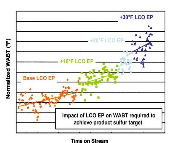
In the figure above, we can clearly see that processing higher end point LCO requires additional operating temperature and increases the deactivation rate. We also see that end point increases of as little as 10 deg F can significantly increase both the required WABT, and the deactivation rate.
Martin Gonzalez (BP)
Difficulty in desulfurizing LCO relates directly to the concentration of hindered substituted dibenzothiophenes (DBT's). The optimal cut-point may be different for each hydrotreater depending on the individual capabilities of that unit (pressure, space velocity, and duty limits). Concentration of DBT's will also vary depending on degree of hydrotreating of FCC feed, and LCO total sulfur concentration may not be a good indicator. Our experience is that coke lay-down rates on catalyst will be greater as the concentration of polyaromatics increases. Thus, it becomes important to also consider LCO gravity, in addition to final boiling point and normal boiling point when considering deactivation rates.
Minh Dimas (CITGO)
We typically target LCO final boiling point instead of 95%. This is because with a constant 95% distillation point, the FBP can vary significantly – at least that is our experience. As the boiling point of LCO material increases, the difficulty to hydrotreat (as opposed to hydrocrack) grows exponentially. Because of this, there is an inherent hydrotreating catalyst life penalty with increased LCO distillation FBP. Of course, the degree of the penalty depends highly on a number of variables including but not limited to the total volume of catalyst, reactor temperature control / quench control, feed nitrogen concentration, feed sulfur concentration, and catalyst type. The unit design (system pressure, hydrogen purity, etc.) has a smaller effect.
Brian Watkins (ART)
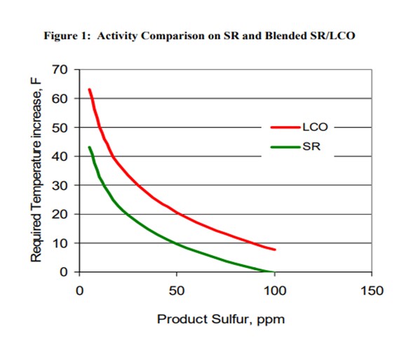
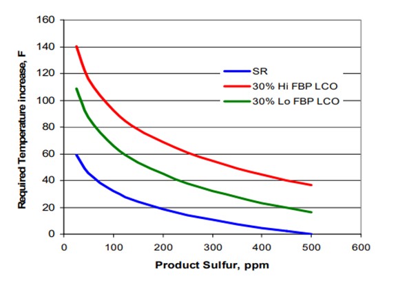
The addition of LCO to a ULSD hydrotreater has several effects such as increased hydrogen consumption, higher required reactor temperatures and possibly shorter cycle time. Figure 1 summarizes some of pilot plant data comparing a SR and a SR/LCO feed blend. It shows that the SR diesel requires a 43°F increase in temperature to go from 100 ppm sulfur down to 10 ppm sulfur. The 20% LCO blend requires almost 20°F higher temperature to achieve the same product sulfur relative to the SR feed. The product from the LCO blend also has a 2 to 3 number lower API compared to the SR product, and hydrogen consumption increases significantly for the LCO blend due to saturation of additional polyaromatic compounds found in the LCO. These latter consequences set limits on the amount of LCO which can be processed and still meet product cetane specifications and also hydrogen availability constraints.
One option to re-gain some of the lost activity in adding additional LCO is to change the end point of the LCO in the feed. ART completed pilot plant testing on an LCO from the same FCC which had been cut at two different end points. Table 1 lists the analysis of the two LCO feeds and shows that the end points differed by about 40° F. The decrease in endpoint lowers the total sulfur by almost 1000 ppm and total nitrogen decreases by 129 ppm.
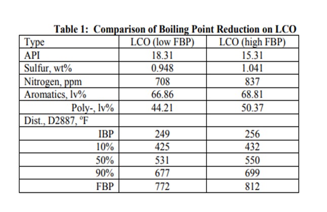
A comparison of activity on the two LCO feeds blended at 30% by volume into SR feed is shown in Figure 2. Over 30° F higher temperature is required to treat the higher endpoint feed to ULSD specification. This difference in activity corresponds to a significant decrease in the hydrotreater cycle length.
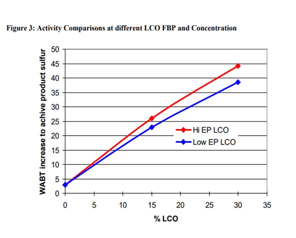
The addition of LCO has a major impact on activity for both the low and high endpoint LCO materials. The required temperature increase for ULSD in going from 0 to 30% LCO for the lower endpoint material is about 1.2° F per percent LCO. Processing the higher endpoint LCO increases the required temperature to about 1.4° F per percent LCO. Figure 3 demonstrates this more clearly in the form of a plot of the required temperature increase as a function of LCO content. Notice from the chart that the activity effects are not exactly linear with increasing LCO content. The first 15% LCO has a larger impact on activity than the next 15%.
Raj Patel (Haldor Topsoe, Inc.)
In the current market, a strong driver for many refiners to increase profitability is to increase the production of diesel; this can be done by increasing the end point of the LCO to the diesel hydrotreater to make more high value ULSD as compared to low value slurry oil.
It is clear that the higher the LCO cut point, the larger the ULSD product pool value. However, a great number of other considerations need to be addressed when increasing LCO cut point to the diesel hydrotreater with the primary concern being reduced catalyst cycle length.
Ideally there would be a single LCO 95% distillation point that all hydrotreating units should target to optimize the ULSD production, i.e., optimize the economics of the diesel hydrotreater. There is, however, no single LCO 95% distillation point that can be considered optimum for all hydrotreaters. Diesel hydrotreaters are designed for processing different feeds and different processing objectives. This results in units with different hydrogen partial pressures and LHSV. The limiting processing objective could be meeting ULSD sulfur, cetane number, cold flow properties, color product end point etc. All these constraints need to be considered individually, and it needs to be determined which will be the limiting constraint not only at SOR but also at EOR. Increasing LCO end point could possibly decrease attainable EOR temperature before the ULSD product goes off spec, effectively shortening the catalyst cycle length. Therefore, there is no single LCO 95% distillation point that can be considered optimum for all hydrotreaters. The ASTM D-86 distillation may hide a lot of the heavy end species, so it is recommended to use ASTM D-2887 distillation when looking at 95% boiling point.
Common for all hydrotreaters is, however, that hydrotreater catalyst life will be penalized with increased cut points. The reduction in catalyst life will come from increase in the required SOR WABT, increased deactivation rates and possibly reduced EOR temperatures:
Activity – Required SOR WABT
As a general rule of thumb for treating 100% LCO, it can be assumed that for every 2-4°F increase in LCO 95% boiling point, the required Weight Average Bed Temperature (WABT) of a hydrotreater must be increased by approximately 1°F to compensate for the increased feed sulfur and feed nitrogen levels. However, this impact is very pressure dependent. If the portion of LCO is smaller, it can be assumed that the required increase in WABT will be almost proportionally less.
If the cut point is lowered towards the end of the cycle, then the increase in required WABT will be regained due to lower severity feed (less sulfur, in particular the difficult sulfur species, and less nitrogen, which inhibits the hydrotreating reactions). If reducing end point for winter month operation, where cold flow properties are limiting, then the hydrotreater can be operated through the winter months with the lighter feed, even if the catalyst is at EOR in summer mode. However, the catalyst life lost from increased deactivation rate when processing the higher end point LCO will not be regained.
Catalyst deactivation
The other effect to consider when raising LCO end point is catalyst deactivation rate. This effect will be dependent on the increase in Tri+ aromatics and nitrogen content of the LCO. As a general rule of thumb the deactivation rate may increase by up to 10% for every 10°F increase in LCO EP. Based on the above it is clear that increasing LCO cut point will negatively impact catalyst life from a standpoint of catalyst activity as well as stability. Increasing LCO cut point (or other heavy portions of the feed in general) must ALSO be managed to meet properties other than sulfur, including cold flow properties, color, cetane number, distillation spec and gravity. Several of these specifications may lead to a lower attainable temperature at EOR due to equilibrium constraints.
The use of the various feed stocks available to the refiner (including LCO) to a diesel hydrotreater is ideally optimized through not only the use of proven kinetic models but also must include refinery LP models. This will provide detailed predictions on the costs and benefits of increasing the cut point of the available feed stocks.
Topsoe has designed diesel hydrotreaters processing LCO including multiple units processing 100% LCO.
Year
2011
Process
Lauren Grimm
US Chemical Safety Board
Question 11: What is the minimum hydrogen sulfide required in the recycle gas for units with low sulfur feed? Do you inject sulfur compounds to maintain a minimum concentration?
Kaspar Vogt (Albemarle)
In some processes, hydrotreating catalysts are used to treat feedstocks containing very low sulfur (below 20 ppm). These processes can include the following:
1. Gulf HPG process for treating pyrolysis naphtha (second stage).
2. Two step naphtha hydrotreating process in steam reforming (ammonia synthesis process).
3. Treating olefinic fuel gas prior to reforming to make synthesis gas for methanol manufacturing.
4. Wax and certain lube hydrofining operations
It appears that in these processes the catalyst slowly loses its HDS activity. This is due to the transformation of the Molybdenum present as activator, and Nickel/Cobalt present as promoters, from their active sulfide form to the inactive metal state. This process is caused by a hydrogen sulfide partial pressure that is too low (see phase diagrams below).
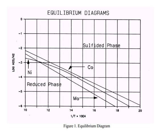
In some cases (usually naphtha units) conditions can arise that contribute to a low H2S partial pressure and could result in metal reduction. Based on the feed properties, operating conditions and product objectives, we can determine whether the unit is or will be operating in a critical operating window. If this is the case, a spiking agent such as DMDS should be added to the feed to boost the H2S partial pressure.
From the phase diagram shown above, we see that the Cobalt is the most critical element. We can begin to move into the Co8S9-phase by decreasing the temperature or increasing the H2S partial pressure by adding sulfur. To move into the "safe" region of the diagram, the Log10 H2S/H2 should be at least -4 at a temperature of 640 deg F.
If the same calculation is done in the reverse order the minimum feed sulfur to avoid metal reduction can be calculated. If we process a 1 ppm sulfur, 70°API naphtha feed at 360 psig at 640 deg F, 80% H2 purity, down to 0.4 ppm sulfur in the product (actual sulfur removal is 0.6 ppm) we conclude that 20 ppm sulfur should be added to avoid catalyst metal reduction. Spiking can be done with a sulfiding agent, e.g., DMDS, DMS.
Minh Dimas (CITGO)
For diesel hydrotreaters, as long as the material being fed to the reactor contains sulfur (i.e., sour feed) and the recycle gas contains 25-50 ppm H2S (by adjusting the amine circulation when necessary), there should not be a need to inject a sulfur-spiking agent into the feed. This ensures a small concentration of H2S at the inlet of the reactor. With reactor temperatures above catalyst activation temperatures, additional H2S is being generated from that point on through the reactor. For us, the sweetest feed is observed when reprocessing off-spec diesel, in which case we may shut down the Recycle H2 Amine Scrubber to preserve the H2S and protect the catalyst.
Tim Lewer (Shell)
In hydrotreating units where the feed sulfur is low and the temperature and H2 partial pressure are low, operation with as low as 20 ppm H2S in the recycle gas has been observed. There is not, however, a universal minimum concentration requirement. The minimum required H2S concentration will vary from unit to unit depending on many factors including, but not limited to: unit feed sulfur concentration, unit pressure, reactor temperature, catalyst type, vent rate, catalyst age, and H2 partial pressure. It is common practice to inject a sulfiding agent such as DMDS to maintain adequate H2S in the recycle gas. In addition, refiners have used sour make up gas streams to provide adequate H2S partial pressure. The guidelines can change based on what catalyst company you talk with, but it all depends on how conservative you want to be. You need to set the H2S low limit to provide a proper buffer zone. It is recommended to discuss H2S concentration requirements for all situations with your catalyst vendor to make sure the catalyst is properly protected against metal reduction.
Gordon Chu (ART)
There is no minimum hydrogen sulfide requirement as long as the feed contains some sulfur as the sulfided catalyst is very resistant to sulfur loss under normal process conditions. We are not aware of any refiners adding sulfur compounds to maintain a minimum H2S concentration during the process cycle.
Year
2011
Process