Question 22: Which is the impact of feed asphaltenes content on hydrocracker cycle length?
Shankar Vaidyanathan (Flour)
The asphaltenes are high boiling, high molecular weight and hydrogen deficient materials that are the least reactive in a hydrocracking environment. Heavy vacuum gas oil may be contaminated by asphaltene entrainment with resid due to inadequate fractionation, inefficient wash or an operational upset in the upstream vacuum unit. Controlling the HVGO distillation end point to limit metals, CCR and asphaltene entrainment may be a better operational strategy while feeding a hydrocracker, than just focusing on VGO yield in the vacuum unit without improving HVGO back-end distillation. Vacuum gas oil is a poor solvent for asphaltenes. Hydrotreated VGO is poorer, so the asphaltene may tend to precipitate out in the lower catalyst beds.
Commercial recommendation is to limit the asphaltenes in feed blend to 0.05 wt.% nC7 insoluble; the licensor or catalyst supplier may have a lower specification by their proprietary analytical test method. High asphaltene content in feed leads to increased catalyst deactivation. The catalyst fouling rate is quite steep; for e.g., doubling the feed asphaltene content may double the catalyst fouling rate from a baseline of 2-3 deg F/month to 4-6 deg F/month, significantly reducing hydrocracker cycle length. Asphaltenes may also precipitate on equipment surfaces leading to fouling and pressure drop issues. Much of the knowledge and catalyst technology for handling asphaltenes in hydrocrackers come from the experience with resid hydrotreaters. Better activity demetallation catalyst or size shaped activity grading may be necessary. Depending on the crude source, additional processing considerations may be needed if the asphaltenes are further compounded with clay type complex to avoid premature pressure drop and plugging of the catalyst beds.
Minh Dimas (CITGO)
We do not check for asphaltenes. We test for Con Carbon (CC) and we try to limit it to 0.05 wt.%. The impact of feed CC in a hydrocracker depends on the H2 partial pressure and the operating temperature of the reactor: high H2 partial pressure and low temperature will saturate coke precursors, but high temperatures and low H2 partial pressure will thermally degrade these precursors to form coke – causing maldistribution, higher pressure drop, and requiring more temperature to achieve a target conversion.
For us, since we limit the HCO 95% to 795 deg F, the deactivation rate slows down.
Raj Patel (Haldor Topsoe, Inc.) Asphaltenes are very complex molecular structures containing metals, nitrogen, aromatics, heteroatomics and aliphatics. The asphaltenes are found in the heavy end of the VGO feed. A poor separation of VGO and vacuum tower bottom in the vacuum column often leads to a heavy tail in the VGO with large amounts of asphaltenes. Such a tail can be very detrimental for the hydrocracker catalysts, leading to rapid deactivation and change in selectivity.
A typical hydrocracker is loaded with a catalyst grading including a demet catalyst to trap most of the feed contaminants such as Ni and V, followed by the hydrocracker pretreatment catalysts removing most of the organic sulfur, nitrogen and polyaromatics and followed by relatively more costly hydrocracking catalyst. The Asphaltenes are very large molecules and require a specialized demet catalyst for effective removal. Topsoe offers demet catalysts especially designed for Hydrocrackers and VGO units designated TK-700 series.
The cocktail of feed metals (Fe, Ni and V), known as permanent catalyst poisons, large amounts of coke precursors such as polyaromatics and organic nitrogen and the very refractive sulfur and nitrogen species in such heavy ends can lead to a fast deactivation of all the catalysts found in the hydrocracker. In most hydrocrackers, the hydrogen pressure is rather high, which reduces the deactivation caused by coke formation.
It is difficult to give a quantitative measure for the direct impact of feed asphaltenes. The amount of asphaltenes correlates with feed metals, amount of PNAs, feed endpoint, organic nitrogen and reactivity of sulfur and nitrogen species to be converted. The amount of asphaltenes is a tool to describe the “toughness” of the feed. Increase in feed asphaltenes content from e.g., 20-30 ppm to around 1000 ppm asphaltenes, which is the case for a heavy tail containing atmospheric residue, can cause the catalyst deactivation to increase from e.g., 1 deg F/month to up to 5-10 deg F/month.
Moreover, a hydrocracker that is operated at high conversion (recycle operation) and runs with high asphaltenes feeds will result in higher HPNA formation. This will also dramatically reduce the cycle length and might cause fouling in downstream equipment.
Processing heavy VGOs and dealing with asphaltenes in particular call for very robust catalyst systems. Besides high performance grading and HDM catalysts, robust bulk catalysts are also of key importance. Due to the unique pore structure of Topsøe’s BRIM™ technology catalysts; these catalysts have a high poisons tolerance. BRIM™ catalysts are able to withstand a contamination level of more than 8-10% Ni+V while still providing activity for removing sulfur and nitrogen.
Optimal protection of the hydrocracker catalyst is of paramount importance, as small amounts of coke precursors and feed metals will change the performance of the hydrocracker catalyst with high deactivation rate and change in selectivity.
Year
2011
Process
Question 20: Pre-hydrotreated feeds and crudes look easy to process on paper. Why is it more difficult than expected to process pre-hydrotreated feeds in a hydroprocessing unit?
Tim Lewer (Shell)
A: Pre-hydrotreated feeds are often the most difficult feeds to process in hydrotreaters primarily because the remaining molecules to be treated are the most refractory. Low sulfur feeds are not automatically the easiest to process; the sulfur species determines the difficulty of processing, not the total sulfur.
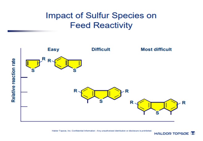
The chart below illustrates the different sulfur species in a distillate stream with boiling point, their relative concentrations, and the relative reaction rates:
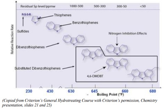
The chart illustrates that as boiling point increases, the molecules that contain sulfur both drop in concentration and reduce in HDS reaction rate. Thus, for example, sulfides are significantly more easily removed than dibenzothiophenes, which are themselves more easily removed than di-substituted dibenzothiophenes. Additionally, as boiling points increase, the nitrogen species also become more refractive and difficult to treat, adding to competition for the active sites on the catalyst.
Pre-treating has the added effect of removing the lighter, less refractive and more reactive species from the stream to be hydrotreated later. Thus, the sulfur molecules that remain are the most refractive and difficult to treat.
Consider, as an example, the following three feeds:
• Feed A: Previously hydrotreated straight-run diesel with 0.2 wt% Sulfur;
• Feed B: Straight-run diesel blended with cracked stock containing 1.29 wt% sulfur;
• Feed C: Straight-run diesel blended with cracked stock containing 0.52 wt% sulfur.
A cursory evaluation of these three feeds might suggest that Feed B is the most difficult to treat, containing the highest amount of sulfur and cracked stock. However, a more in-depth analysis, specifically a gas-chromatograph (GC) of sulfur species with boiling point reveals significantly more information:
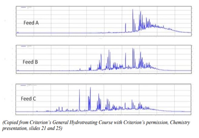
Here, the relative concentrations of each molecule are measured along the y-axis, and the boiling point of each species is measured along the x-axis.
Evaluating this GC illustrates that the most refractive sulfur is in Feed A with 94% refractive sulfur, followed by B with 48% refractive sulfur and finally Feed C with 37% refractive sulfur. Thus, pretreating increases a feed’s processing difficulty by removing the “easy” sulfurs and leaving only the “hard” sulfurs to remove.
Traditional models are based on correlations of bulk properties, not molecules. In such models, pre-hydroprocessed feeds seem easier than they are because their total sulfur, total nitrogen, and density are low. But there can be a 10x to 100x difference in reaction rates between “easy” sulfur compounds and “difficult” compounds such as di- and tri-methyl dibenzothiophenes (DM-DBTs and TM-DBTs). The same applies to “easy” and “difficult” nitrogen. Low severity hydrotreating removes easy molecules, leaving tough ones behind. In ULSD, almost all of the remaining sulfur is present in DM-DBTs and TM-DBTs. An additional round of low severity hydrotreating won’t do much. They can only be removed by high-severity treatment.
Hydrocrackers frequently process feeds that were previously hydrotreated in low-severity units. These feeds usually remain more difficult to process than the non-hydrotreated feeds, especially if they come originally from cat feed hydrotreater (CFH) units or Syncrude's derived from Resid. Previous treatment removes sulfur and nitrogen, saturates aromatics, and might even clip offside chains. The resulting products boil below 1000°F, but they contain large polynaphthenic compounds. Due to strong thermodynamic drivers, these are very susceptible to dehydrogenation under high temperature. When the large PolyNapthenics lose hydrogen, they form large PolyAromatics which condense readily into coke.
Shankar Vaidyanathan (Flour)
Pre-hydrotreated feeds are more difficult to process because the conventional inspections of bulk gravity, sulfur and distillation do not adequately define the characteristics. Additional information such as chemical speciation and molecular distribution over the boiling range may be necessary. Upstream upgraders are all not equal in process configuration so a good idea is to evaluate how the syncrude barrel is constituted. In general, deeper hydrogenation, higher pressures and larger reactors may be necessary to process pre-hydrotreated feeds. The chemical hydrogen uptake estimates need to be prepared with special care for pre-hydrotreated feeds. Catalyst fouling rates need to be defined based on pilot work.
Downstream processing of pre-hydrotreated SCO derived diesel for ULSD may require ring opening or deeper hydrogenation for aromatic saturation in order to meet sulfur, cetane and gravity specifications. The nitrogen and aromatic content of pre-hydrotreated SCO derived gas oils is high and this can be a challenge in downstream treating for FCC feed. If the pre-hydrotreated gas oil is partly derived from an ebullated bed process, consider the fact that it had already passed over a high pressure, high residence time hydroprocessing environment while defining the downstream hydrocracker treating and conversion objectives. Some refiners have also seen higher levels of suspended sediments, metals and silica so pay specific attention to catalyst system selection, configuration and layering to avoid pressure drop issues. Other refiners have faced heat balance issues, and a few have also had compressor capacity issues.
Kaspar Vogt (Albemarle)
Simply put, the easy sulfur and nitrogen bodies have been removed and the hard sulfur and nitrogen molecules remain. Pre-hydrotreated feeds went through an upgrading process, e.g., coking, followed by preliminary mild hydrotreating.
Pre-hydrotreating is an economic way to meet feed specifications without consuming too much in hydrogen or investing in a high-pressure hydrotreating unit. Pre-hydrotreated crudes are also often blended with lighter feeds, e.g., naphtha, to reduce density and improve pumpability.
The pre-hydrotreating process removes easy Sulfur, but only part of the refractory Sulfur and Nitrogen, and only saturates PNAs. Typically, at least in case of a mild pre-hydrotreating process, N/S ratio is higher than in non-pretreated feeds, as on average Sulfur species are easier to remove than Nitrogen species.
Typical characteristics of a pre-hydrotreated feed are thus a very high refractory Sulfur fraction (can easily be 50% of the total Sulfur vs typically 7-9% in a regular LGO), a high concentration of aromatics and mono/polyaromatics ratio (e.g., 85% vs 55-60% of a regular LGO) and a very high N/S ratio (0.15 vs 0.01 in a regular LGO).
Apart from the shift in the N/S ratio, which is particularly evident in case of a mild pre-hydrotreatment, or the MonoAromatics/PNA shift, the best way to recognize and characterize pre-hydrotreated feeds is by means of Sulfur or Nitrogen specific speciation analyses, like GCxGC-S/NCD. These techniques typically reveal a shift towards a relatively higher concentration of the most refractory S- and N-species, like 4, 6-DMDBTs and highly refractory organic basic Nitrogen, like acridine. In addition, the still large presence of N-containing PNAs makes the feed prone to coking on the catalyst surface. When light feeds are added to reduce density, low hydrogen partial pressure may be further lowered during operation due to higher feed evaporation. This can make coking more pronounced, especially at the reactor bottom where temperature is the highest. All considered, it is thus very important to know the source of a feed and if it has been upgraded and pre-0hydrotreated.
Brian Watkins (ART)
Opportunity feedstocks, having already been processed through conventional refinery processes, pose unexpected challenges to refiners wishing to incorporate them into the distillate pool. Some of these streams have proven to be significantly more difficult to process underscoring the fact that it is important to understand the potential impacts of processing new feed streams in order to avoid unpleasant surprises. Significant differences in feed reactivity for various pre-processed feeds components are not necessarily anticipated from the usual bulk feed analyses.
When considering the use of synthetic crudes an understanding of the upstream processing is important. Production of synthetic fuels involves a combination of several processes in order to accommodate downstream processing. These upstream processes include coking or an ebullating bed reside operation, followed by a hydrotreating or hydrocracking operation in order to produce a lighter grade material. These hydrocracking units tend to operate at severe conditions in conjunction with high hydrogen partial pressures. At these conditions, the removal of all the easy, less refractory sulfur is readily achieved, and the majority of the multi-ring aromatics are saturated. This leaves a product that is relatively low in sulfur and PNA’s and when added to the feed to a ULSD unit gives rise to a surprisingly difficult feedstock to process. These products are then blended in with other heavier materials as a diluting or cutting stock and sent downstream as synthetic crude.
Likewise, the use of diesel range products from an H-Oil®, LC-FINING unit or fixed bed residuum desulfurizer can also have a significant impact on downstream diesel catalyst activity for similar reasons. The general properties of these types of diesel feeds often indicate that they may be relatively easy to hydrotreat due to their low sulfur content and API gravity, which is often similar in appearance to straight run (SR) materials. Table 1 lists the properties for several of these diesel feeds including the diesel product fractions from an ebullating bed residuum (EB) unit, a fixed bed residuum (FB) unit and a diesel fraction from Canadian synthetic crude.
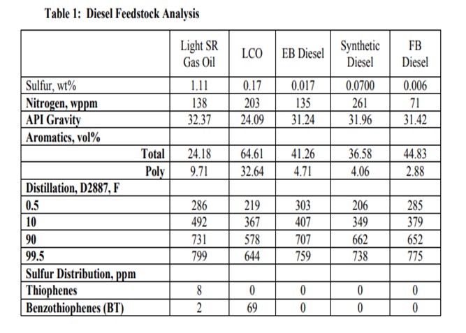
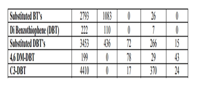
Figure 2 shows the activity difference between a SR and a blended SR / Synthetic diesel. Note that at higher product sulfur, the two feedstock’s respond similar to each other. As the application becomes more demanding, the required reactor temperature increases dramatically for the synthetic diesel feed as compared to the SR feed. The blended feed requires more than 25°F higher temperature relative to the SR to achieve ULSD sulfur levels.
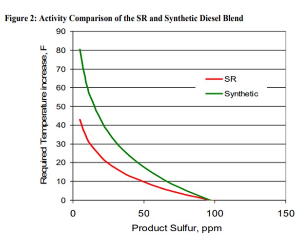
It is reasonable to expect that the upstream hydroprocessing of the synthetic diesel material results in a feed that behaves similarly to other previously hydrotreated feedstocks like those from the EB and FB residuum applications.
Advanced Refining Technologies can work closely with refining technical staff to help plan for processing opportunity feeds such as those discussed above. One of the keys is being aware of the potential impacts processing certain feeds will have on unit performance. Feeds which have been previously processed present unique challenges and ART® is well positioned with its experience at providing customized catalyst systems for ULSD applications. Opportunity feeds provide yet another objective to consider when designing the appropriate catalyst system to maximize unit.
Raj Patel (Haldor Topsoe, Inc.)
The main reason is that pre-hydrotreated feeds have already had the easy sulfurs removed in the initial hydrotreating step and thus when this pre-hydrotreated crude is blended with other crudes in the refinery and the intermediate cuts after the crude unit reach the next step in hydrotreating, the overall properties (i.e., API, distillation, total sulfur, etc..) may seem to be easily processed but unknowingly the sulfur distribution is heavily weighted to the difficult sterically hindered species (4,6 dimethyldibenzothiophenes and heavier).
To give an example of the impact of the sulfur distribution on the operation of a hydrotreater, Haldor Topsoe has evaluated a refiner’s Ultra Low Diesel Unit feed at two different times in the run. The feed to this unit appeared to be very similar in feed properties routinely monitored by the refinery however the hydrotreating temperatures required were showing a difference in severity. Upon review of the sulfur speciations of the feed retain samples, the following results were determined:
Feed Sample #1
Total Sulfur (ppm) 4900
4, 6 Dimethyldibenzothiophene (ppm) 90
4-methyldibenzothiophene (ppm) 154
4, 6 DMDBT/Total Sulfur (%) 2
4-MDBT/Total Sulfur (%) 3
Feed Sample #2
Total Sulfur (ppm) 5080
4, 6 Dimethyldibenzothiophene (ppm) 212
4-methyldibenzothiophene (ppm) 315
4, 6 DMDBT/Total Sulfur (%) 4
4-MDBT/Total Sulfur (%) 6
This difference between what appeared to be similar diesel feeds at first glance required a 25°F increased WABT to make the same ULSD product with Feed #2.
Another example is found below.
Comparison of two LGOs with equal total sulfur content but different history
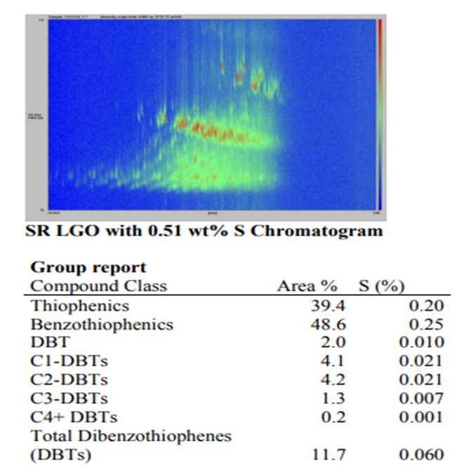
In the “raw” straight-run LGO that has not been hydrotreated, the distribution of sulfur is dominated by the lighter boiling and higher reactivity compounds – sulfides, thiophenes, naphthenothiophenes and benzothiophenes. These “easy” sulfur compounds constitute 88% of the sulfur in the feed.
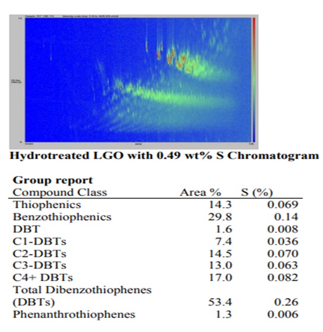
In contrast, the sulfur distribution in the hydrotreated LGO shows that more than half of the sulfur is present as dibenzothiophenes (DBT) structures with one or more alkyl groups. These sterically hindered species are the slowest reacting sulfur molecules existing and will greatly impact the overall reactivity of the feed.
Year
2011
Process
Question 21: What needs to be considered when processing LCO or increasing the amount of cracked feed in a hydrocracker?
Tim Lewer (Shell)
It is important to ensure that sufficient H2 is available to satisfy the minimum required H2/oil ratio because hydrogen consumption will increase significantly. Review the make-up gas compressor design and H2 sources to ensure that adequate H2 can be provided. Also, it is important to consider the additional heat release/reactivity of LCO type feeds. Adequate heat removal and furnace turndown/controllability can be issues. Activity grading of the catalyst can help to address heat release issues at the top of the reactor. Finally, increasing the amount of LCO will increase the feed nitrogen content leading to higher ammonia passivation of the cracking catalyst requiring higher temperatures. Watch out for a runaway reaction in the cracking beds if there is a rapid drop in LCO feed rate.
Minh Dimas (CITGO)
H2 availability is a key parameter here (since cracked feed will consume more H2 and has a higher tendency to make coke). Also, attention should be taken in relation to higher bed exotherms due to the higher heat released by the aromatic saturation reactions.
Kaspar Vogt (Albemarle)
Processing more cracked feeds will increase the olefins content and typically also the aromatics content. Hydrotreating these in the pretreat section of a hydrocracker will lead to an increase in H2 consumption and exotherms. For LCO the aromatics concentration will be up to 3 times the straight run diesel concentration. The LCO nitrogen and sulfur content vary depending on the presence or absence of an FCC feed pre-treater. Increasing the blend of cracked stock to straight run feed means more exotherm, especially in the first bed as more olefins and aromatics are saturated. So one of my concerns is how you introduce or increase the blend ratio of cracked stocks. Quench control and available reserve hydrogen quench becomes more important as the cracked stock ratio increases. This is especially true if the unit is processing above design feed rates. With increased bed exotherm there also is increased H2 consumption at the same conversion level.
Year
2011
Process
Question 23: What is the impact of HPNA (Heavy PolyNuclear Aromatics) on hydrocracking catalyst activity, stability. and yield selectivity?
Kaspar Vogt (Albemarle)
The impact on hydrocracking catalyst deactivation and yield selectivity due to precipitation of Heavy PolyNuclear Aromatics (HPNA) is typically based on several criteria.
- Unit configuration
- operating in recycle mode
- operating in once through mode
- Conversion level and therefore unconverted oil bleed rate from the unit
- Feed type and feed properties
- Catalyst type
HPNA FORMATION
The formation of PNA's is an undesirable side reaction that occurs in hydrocrackers. The HPNA's are generated by three primary mechanisms:
- by condensation of two or more smaller PNA's present in the hydrocracker feed;
- by dehydrogenation of larger hydro aromatic cyclic systems; or
- by cyclization of side chains onto preexisting PNA's followed by dehydrogenation.
Dehydrogenation is more favored as reactor temperature increases. Operating at the lowest possible temperature will best manage the HPNA formation.
In the first pass through the reactor, some HPNA's are produced from the smaller PNA's that are present in the feed. The PNA's are preferentially adsorbed on the catalyst because they are more polar than are most of the other feed components. Their polarity increases as their side chains or saturated rings substituents are removed or dehydrogenated (aromatized) in the process. This removal of some side chains further increases the tendency of the HPNA's to adsorb and condense to form larger HPNA's. Further condensation of the HPNA's represent the last steps in catalyst coking.
The HPNA's are high boiling and thus concentrate in the fractionator bottoms stream, which in recycle hydrocracking is routed back to the reactor section. Eventually, the equilibrium concentration of the HPNA's is reached in the reactor effluent and recycle liquid. The HPNA's build up to the limit of their solubility at temperatures used for the condensation and separation of the reactor products.
The formation of HPNA's depends on many factors. The amount and type of PNA precursors are normally related to feedstock composition and boiling range.
Heavier feeds contain more HPNA precursors. In addition to high endpoints, HPNA precursors may also be indicated by high levels of olefins, aromatics, asphaltenes, or heteroatoms in the feed.
Operating severity also has an effect. As conversion increases, the concentration of PNA's with five or more rings increases. With catalyst deactivation, higher reactor temperatures are required, and HPNA levels increase. This temperature effect becomes more significant as conversion approaches 100%.
Catalyst selection also impacts the amount of HPNA generation. In first stage applications using base metal catalysts, pilot plant studies indicate that as the catalyst activity and hydrogenation function increase HPNA generation decreases.
HPNA IMPACT ON EQUIPMENT
HPNA precipitation in equipment downstream of the reactor depends on the concentration of HPNA and operating temperature. Generally we expect the effects of HPNA to become significant when the concentration increases above the range of 50 to75 ppm. As concentrations increase with low unconverted oil bleed from the unit, the impact to equipment, catalyst activity and catalyst deactivation becomes more prominent. Precipitation temperature generally begins to occur between 300 deg F and 350 deg F depending on the concentration. This will impact equipment such as the reactor effluent air condenser (REAC) and exchanger equipment in recycle oil or unconverted oil service.
HPNA IMPACT ON CATALYST DEACTIVATION, YIELD SELECTIVITY
The deposition of HPNAs diminishes the hydrogenation function as evidenced by loss in saturation activity. In other words, as condensation reactions increase and coke formation accelerates, catalyst deactivation accelerates. The loss of the hydrogenation activity or metal function impacts product quality.
As activity is lost, the reactor catalyst temperature is increased and in order to continue the same product conversion, the deactivation rate increases. The increased catalyst temperature, depending on the type of hydrocracking catalyst utilized, generally results in a significant shift in heavy yield selectivity. Increased catalyst deactivation resulting from condensation reactions of HPNA to coke accelerates the deactivation, and therefore increases catalyst temperature to keep desired economic conversion to products. By employing high zeolite catalyst systems (rather than lower zeolite and amorphous catalyst systems) selectivity shifts as much as 2% by volume have been observed in commercial applications.
Generally, as the UCO bleed stream increases and HPNA is purged from the system, in most cases, catalyst activity will typically return, provided that condensation reactions have not progressed to the point that coke deposition is affecting catalyst activity.
Raj Patel (Haldor Topsoe, Inc.)
HPNA’s are high molecular weight condensed aromatic molecules containing multiple aromatic rings with boiling above 500°C. Analyses of HPNA deposits on heat exchanger and aircooler surfaces show compounds with up to 30 aromatic rings are present. Once these compounds are formed by undesired side reactions in the hydrocracker, they are virtually impossible to convert in the hydrocracker. If not removed from the hydrocracking reaction system, they will continue to build up in the recycle oil stream.
The HPNA in the recycle oil stream, typically in the several hundred ppm range, have an adverse impact on the catalyst primarily in the form of catalyst stability. The HPNA molecules will lay down as coke and cause rapid deactivation of the catalyst. The yield selectivity is impacted as a result of the higher required reactor temperatures as the catalyst deactivates.
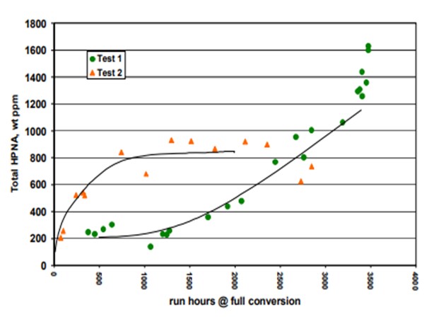
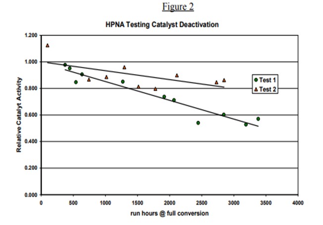
Topsoe has studied in detail the impact of HPNA on catalyst stability in our pilot plants. Results of some of the testing is provided below. Two tests are shown. The HPNA concentration is allowed to build up in Test 1 while it is controlled in Test 2 as seen in Figure 1. Figure 2 shows the catalyst activity over time for the two tests. The catalyst deactivation is very rapid for Test 1 where HPNA are allowed to build up and is under control when HPNA are not allowed to build up.
Haldor Topsoe employs a number of approaches to both minimizing the impact of HPNA on the catalyst and equipment and also minimize the need for unconverted oil (UCO) purge and the corresponding loss of product yield. The key design elements are listed below:
• Increased hydrogen partial pressure will suppress HPNA formation. Therefore, the selection of system pressure must be economically balanced with the desired overall conversion in the hydrocracker.
. • The use of catalyst with excellent hydrogenation activity in both pretreatment and hydrocracking service to saturate and convert HPNA precursors and thereby minimize the formation of HPNA.
• The use of a hot high-pressure separator in the reactor section will minimize the possibility of heat exchanger fouling due to HPNA precipitation as the reactor effluent is cooled.
Haldor Topsoe has come up with a new revolutionary process technology to control HPNA build up while minimizing the loss of bleed. This process technology consists of a steam stripper utilizing the existing steam supplied to the fractionator. The quantity of steam is relatively large in comparison to the small quantity of unconverted oil to the stripper. This provides the driving force required to vaporize up to 80% of the oil to the stripper. The HPNA that cause deactivation of the catalyst are high boiling and are not vaporized in the stripper and are eliminated in the 20% bottoms stream. The bleed rate required to control the HPNA is thus reduced to 20% of the original bleed rate. The payback for Topsoe’s unique process technology to control HPNA is typically less than six months.
Year
2011
Process
Question 24: Do you use Safety Instrumented Shutdown systems in gasoline units (reformers, alkylation, isomerization, hydrotreaters)? How many of you use DCS-based vs. dedicated hardware shutdown systems?
Ujjal Roy (Indian Oil Corporation)
In order to comply with auto fuel policy of Govt. of India for introduction of Euro-III and Euro-IV in the country and in all major cities in India respectively, all IOC refineries (10 nos.) had to take up MS Quality Improvement Projects which included new units and revamp of existing units including catalytic reformers, isomerization units, selective hydrogenation units, benzene saturation units and hydrotreaters. All these projects were initiated in 2004-05 and commissioned between 2007 and 2010. All these units are designed with ESDs/PLCs for safe shutdown applications. These ESDs/PLCs are certified for SIL in line with IEC-61508 & 61511 by certified agencies.
However, for the new grass roots refinery of 300,000 BPSD, that we are building and that will go on-stream in 2012-13, we have carried out SIL review for all process plants, general facilities, storage & handling and offsite & utilities complying with IEC-61508 and 61511 to implement required SIL for Safety Instrumented Shutdown (SIS) systems. These studies are based on probability of happening, consequences, frequency, risk of injury, potential financial loss and impact on environment and carried out after HAZOP.
In our country, we have statutory government body which is Oil Industry Safety Directorate (OISD) and their standard demands SIS for all process and operations when mechanical integrity of process equipment, control systems and other protective devices are not adequate to mitigate the potential hazards. OISD advises Layer of Protection Analysis (LOPA) team to recommend use of SIS when design changes for built-in safety cannot mitigate the risk.
It is generally preferable that all protections systems be kept functionally separate from Basic Process Control Systems (BPCS) to facilitate its operation independent of BPCS. It facilitates protection system to operate when process control system is in fault or fails to prevent abnormal process conditions. Also, depending upon the degree of uncertainty in process safety time, the SIS should be capable of completing its actions within one-half of its allocated process safety time which may be difficult through DCS. Keeping this in view, we have progressively changed over from relay based dedicated hardware systems to PLCs/ESDs in all gasoline units.
Also, we are using in new refinery design, High Integrity Protection System (HIPS) which is a type of SIS to prevent over pressurization of the plant and to reduce design flare load. These HIPS are dedicated solid-state/non-programmable logic systems and are independent from other instrumented systems.
Brad Palmer (ConocoPhillips)
Greater than 70% of ConocoPhillips refineries have Safety Instrumented Shutdown (SIS) systems on at least one or more gasoline processing units (Reformers, Alkylation Units, Isomerization Units, and Hydrotreaters). Nearly all SIS systems in ConocoPhillips are dedicated hardware systems and all of them will be by 2016. ConocoPhillips has a standard requiring all SIS systems be dedicated hardware.
Year
2011
Process
Question 25: How do you manage process hazard analysis (PHA) scenarios related to corrosion?
Brad Palmer (ConocoPhillips)
First, ConocoPhillips has developed generic PHA scenarios for each major technology to determine what scenarios are applicable to a particular unit. These tables contain initiating categories (such as Corrosion), potential causes and consequences, possible safeguards and suggested consequence rankings. These documents serve as aides to PHA teams with varying levels of experience and reminders of certain scenarios to be considered. They also serve to calibrate a PHA team’s consequence ranking across multiple refineries within the company and industry. These tables are intended for use throughout the PHA process and cover the range of operating equipment and conditions, including alternate operating conditions such as Reformer regeneration.
Second, Corrosion/Materials/Inspection are valuable participants on the PHA team. These experts can provide an overview of the potential for corrosion or damage in the unit. They can also review the current equipment condition and any operating concerns that could cause corrosion or other damage mechanisms. ConocoPhillips next revision of our PHA Required Standard will require PHA teams to complete the Fixed Equipment MI Review posted at the end of this response.
Third, when a PHA team identifies scenarios that are corrosion related (or any other damage mechanism); they review them with the Corrosion/Materials/Inspection/Reliability specialists to verify a risk based (API 510/570) or a rule based (API 580/581) program is in place to prevent and mitigate the scenario. If a program does NOT exist, recommendations are issued for program development. If a program does exist, the team reviews the effectiveness of the preventative safeguards, whether the scenario has occurred, and if so, the effectiveness of the mitigative safeguards.
Fourth, Corrosion and other damage mechanism scenarios are not “LOPA-able” since there is no known initiating cause likelihood. Therefore, other risk management tools must be employed to prevent and/or mitigate high PHA consequence scenarios. These tools can include robust material design, robust Corrosion/Materials/Inspection/Reliability programs and Reliability Operating Limits (ROLs). ConocoPhillips has established a Reliability Operating Limit (ROL) Required Standard which includes generic ROL tables for each major technology to serve as reminders to refinery personnel of certain parameters to be monitored and potentially alarmed to prevent these damage mechanism scenarios. The ROL program is being implemented by tiered approach to prevent acute (high risk/short term) conditions with potential process safety consequences, followed by medium risk scenarios and then chronic (low risk/long term) problems. These ROLs may include, for example, Reformer regeneration caustic-solution pH monitoring for corrosion prevention or reactor outlet temperature monitoring for HTHA prevention, etc.
These operating limits are evaluated and approved by each site. Exceedences are reviewed by the appropriate experts to determine if operation is safe to continue or if alternative actions must be taken, i.e., inspection, repair or replacement.
Finally, it is important to realize that the LOPA risk management tool can only be applied to a portion of the high consequence PHA scenarios. Depending on the unit, “LOPA-able” scenarios may be a small subset of identified risk 4/5 consequences. For example, only 15% of the ConocoPhillips Reformer scenarios, risk ranked 4/5, fit the LOPA methodology. Other risk management tools are being used, and in some cases are being developed, to address these remaining scenarios: Safe Operating Limits (SOLs), Reliability Operating Limits (ROLs), Compressor Hazard Assessments Guide, Pump Hazard Assessment Guide, Relief System Required Standard, robust Inspection program, Engineer Design and robust Operator Training. Although these numbers may not apply to other technologies, the point is clear; more focus needs to be made on multiple risk management methodologies if a refinery wants to adequately protect against all process hazard scenarios.
Example of Fixed Equipment Mechanical Integrity Review
The following checklist items shall be reviewed during the PHA with input from Inspectors and/or Corrosion Engineers who have experience with the process under review. Some items may be directly addressed during the review. Other items may simply be a check to assure that proper Mechanical Integrity activities/assessments are happening outside of the PHA process. Not all checklist items will be applicable to the process under review.
1. Brittle fracture of materials not designed for low temperature conditions
2. Low-silicon carbon steel in sulfidation service
3. Vibration that could lead to fatigue failure of piping, threaded connections, unsupported overhead weight or exchanger tubes
4. Contamination that could cause stress corrosion cracking (e.g. wet H2S, caustic, amines, chlorides, polythionic acids or corrosion fatigue cracking in deaerators)
5. High temperature hydrogen attack, accelerated creep or other ageing or embrittlement phenomena, Nelson curve operating limits
6. Water wash and chlorides control
7. Rapid corrosion due to change in flow rates, injection or other mix points, changes in flow patterns or injection system failures
8. Thermal fatigue cracking due to large temperature cycling or severe temperature swings
9. Dead legs that could freeze and rupture (i.e. especially in light hydrocarbon services)
10. Localized hot spot or excessive temperature that could cause equipment rupture from short term overheating (e.g. furnace tubes, transfer lines, catalyst vessels)
11. Liquid slugging of piping or flare lines that could cause piping failure due to hydraulic shock and transient overstress conditions
12. Hot spots from improper tracing installation that could cause localized corrosion
13. Localized corrosion or cracking of heat affected zones of welds in alloy piping
14. Fouling or plugging of inlet or outlet piping of relief devices
15. Caustic cracking of non-stress relieved equipment from boiler feed water leaks or other caustic containing streams
16. Dew point corrosion due to process upsets
17. Process upsets that introduce moisture into moisture free environments or remove moisture from environments reliant on moisture for the protection of the system
18. Liquid carryover in gas streams, or velocity changes of mixed phase streams causing accelerated corrosion/erosion (e.g. downstream of control valves)
19. Changes in pumping or compressor capacity leading to increased corrosion rates
20. Changes in process conditions leading to increased corrosion under insulation (e.g. idling of normally hot equipment
21. Changes in pH or corrosion control measures leading to increased corrosion or cracking
22. Changes in feed compositions adversely affecting corrosion rates (loss of trace amounts of corrosion inhibitors)
23. Potential to introduce a new corrosive material
24. Issues with CUI (corrosion under insulation), buried piping/soil-air interface and piping over water
Praveen Gunaseelan (Vantage Point Consulting)
The question as stated is general and pertains not just to gasoline processes but to overall refinery safety. There are certain systems for which corrosion issues may arise during a PHA. When a PHA team encounters a corrosion-related scenario, the team will typically propose mitigation measures, such as appropriate material selection, corrosion coupons, etc. In such instances, it is imperative that the PHA team include or consult with a subject matter expert on corrosion. However, it must be recognized that PHA is not the primary approach to identify and address refinery corrosion problems. Corrosion within a facility is more comprehensively addressed under the Mechanical Integrity (MI) element of Process Safety Management (PSM) programs. A Mechanical Integrity program may oversee implementation of risk-based inspection, periodic inspection and monitoring, asset management software, etc.
Useful references:
API Recommended Practices (RP) 580 and 581 provide guidelines for risk-based inspection. Publication 42, “Corrosion in Refineries” by the European Federation for Corrosion, contains detailed reviews of corrosion problems in catalytic reforming and HF alkylation, and provides strategies for corrosion management.
Erik Myers (Valero)
While our sites do not necessarily have a uniform methodology on this deviation, all sites take a similar approach. Corrosion is a Cause, usually used in Leak/Rupture Deviations, that is covered in each node for each PHA. We rely on the SMEs participating on the PHA team to state whether or not corrosion is an issue and how this is addressed if it is an issue. Safeguards are listed by the Team such as chemical injection, inspection etc. Previous incidents are also reviewed in each PHA.
Year
2011
Process
Question 26: When you test for free HF and organic fluorides in alkylation unit products (alkylate, butane, propane), what are your typical observed levels? After HF breakthrough in our butane product, why does our treater still have plenty of KOH remaining? Is there any way to regenerate KOH during the run? Do others maintain a heel of KOH in the bottom of the alkylate storage tank to neutralize traces of HF?
Erik Myers (Valero)
These series of questions overlap quite a bit. The following answers address each question in the approximate order of those questions.
Our sites vary in the type of testing with most sites testing for combined (organic) fluorides in at least the propane and butane streams. Multiple stream points are typically tested dependent on what the monitoring goals are. Typical levels upstream of any treating are:
• Propane - 200 ppm
• Butane – 600 - 1000 ppm
• Alkylate – less than 100 ppm
Combined fluorides measured upstream of treating can be used as an indication of the completeness of the alkylation reaction. There will always be some level with the typical values noted above. Higher levels indicate potential issues with the upstream operation. The above values are for typical operations. Key contributors to increases in combined fluorides are low acid strength (below 85%), low reactor temperature (less than 80 o F), decreased contact time and low I:O ratio. Any of these can lead to increases in the amounts of all levels of combined fluorides. Propyl and butyl fluoride can increase by orders of magnitude with low acid strength. Post treatment levels of combined fluorides should be well under 10 ppm, typically.
Defluorinators are typically installed on the propane and butane streams, followed by KOH treating. These systems are occasionally used on the alkylate product stream. Water and HF are the products of the defluorination reaction. HF reacts with the defluorinator alumina to make aluminum fluoride trapped as part of the defluorinator alumina. This leads to potential of trace HF in the defluorinated stream if the remaining active alumina does not convert the HF. There is typically a lead – lag arrangement on the defluorinators to allow continued treating of the product streams. The downstream KOH treater is installed to dry the defluorinated product and remove any trace HF. It is less common to have a lead – lag for the KOH treaters but two of our sites have this arrangement on at least one stream. Some of our sites have water collection pots upstream of the KOH treaters to lessen the load of those treaters. To measure the effectiveness of the defluorinators and as an aide in determining optimum change out frequency, the streams are ideally measured before, between and after the treaters (with the downstream measured after KOH treating). The sample between the lead and lag defluorinators is used for confirmation of whether an alumina changeout is required. The upstream sample, along with the product flow rates can be used a predictive tool in scheduling lead defluorinator changeouts. The spent alumina can also be sampled and analyzed by the alumina supplier and compared to these predictive results for further alumina changeout optimization as well as verification of the hydrocarbon stream fluoride testing. One site uses a typical fluoride concentration and then a throughput totalizer to determine changeout timing, then analyzing the spent alumina to confirm loading.
Aside from the trace HF noted from the defluorination reaction free HF should not exist in the alky propane if the HF Stripper has adequate reflux and never show up in the normal butane or alkylate product. The primary cause for free HF is spent alumina in the defluorinators or severe loss of tower temperature profile in the alkylation fractionation tower(s). less than 1 ppm. Only one of our sites typically checks for free HF with the values being less than 5 ppm.
The KOH treater is typically a walnut bed downstream of the defluorinators. Our sites utilize both walnut and flake KOH, with walnut being typical. Our units are split with 50% have upflow and the other half downflow. This is typically an indication of the original unit licensor design. As noted earlier, water and HF are the products of the defluorinator. If the there is an HF breakthrough to the KOH treaters, it is most likely due to a spent defluorinator, where there is no more alumina to react with the HF. Significant breakthrough is important to avoid. Large amounts of free HF can cause the KOH treater to heat up resulting in hydrocarbon vaporization and unfavorable conditions for HF removal. (In a propane KOH treater, melting of the KOH and then freezing it in the outlet piping has actually been observed). One of our sites has an emergency alarm for high butane KOH treater outlet and delta temperature with another site having an SIS diversion for high C3 KOH treater temperature. The noted upstream and downstream sampling of each defluorinator is a key to staying on top of this processing area of the alky.
If KOH is still present in the treater while HF is measured in the product it is most likely caused by poor distribution through the KOH bed, either from channeling or crusting on the top of the KOH bed, sometimes caused by low amounts of water in the feed to the KOH treater. This low water content prevents the removal of KF (formed by the reaction of the KOH and the HF) from the KOH treater. Our sites have utilized either routine steam or water injection to the KOH treaters to prevent this.
Circulating KOH (typically used in the acid relief system neutralization system) can, and typically is, regenerated in a batch mode. We are not aware of a method to regenerate the solid fixed bed units as the KOH is converted to water and drained from the system. Three of our sites have two KOH treaters (either in parallel or series), allowing monitoring and changeout to be accomplished without compromising product quality. Residual KOH / water from the KOH treater changeouts can be utilized for make up in the circulating KOH system noted above.
Only two of our sites presently utilize a caustic heal in the alkylate product tank. This has been utilized at other sites in the past. This was done either as a preventative measure or as a result of previous issues with tank bottom corrosion. It is a common recommendation from the licensor. If this method is used, the tank water draw should be monitored frequently to measure changes and prevent loss of protection. The mechanism for tank bottom corrosion is either HF breakthrough from slumping of the fractionators, an exchanger leaks that routes acid to the tank or water in the alkylate product tank that leads to hydrolysis of the combined fluorides in the alkylate to HF if the residence time in the tank is long enough. The noted monitoring of any water draws and then ensuring that there is not water is another preventative measure for this.
Brad Palmer (ConocoPhillips)
Typical organic fluoride levels in alkylation unit products, upstream of any post-treatment, have been reported as 40-60 ppm (Alkylate), 200-400 ppm (Butane), and 300-600 ppm (Propane). Inorganic fluorides are not typically measured. Defluorination and KOH treating will reduce propane and butane organic fluorides to 10 ppm or less. Inorganic fluorides will be less than 1 ppm after treatment. Thermal defluorination, occurring in the heater passes, can further reduce organic fluorides in alkylate. Maintaining the fractionator bottom temperature above 320°F will thermally defluorinate any organic fluorides in the tower bottom thereby minimizing organic fluorides in the alkylate.
Un-used KOH material at breakthrough signifies bed channeling and/or a very dry system that allows KF to coat the KOH material. Defluorinator chemistry reacts organic fluorides with alumina to form alumina fluoride and water; an intermediate reaction product is HF, which may leave the defluorinator unreacted. The KOH treater is primarily a dehydrator and secondarily an HF neutralizer. As the KOH dries the LPG stream, the water "cleans" the KOH as it makes a sludge that is drained from the vessel. Any HF breakthrough from the defluorinator will react with the KOH to form KF and H2O. If there is very little organic fluoride to react in the defluorinator, there will not be much water formed to slough the KF off the KOH pellets. Some sites have used water injection to help "clean" and utilize the KOH material under dry conditions.
There is no effective way to regenerate solid KOH in the KOH treater with the vessel on-line. Water injection might be effective to refresh KOH that has been coated with KF as previously described.
It is a common practice to use an alkali heel in the alkylate storage tank. This is not for neutralizing HF, but is to counter-act iron fluoride scale leaving the process with alkylate which can form low pH hydrates on the tank bottom. The alkali heel should be tested routinely to ensure it remains basic.
Year
2011
Process
Question 27: What are the pros and cons of alkylating delayed coker butylenes (co-processed with FCC butylenes)? Does this require higher isobutane recycle? Should we consider processing them in a separate reactor? What are the economic alternatives to alkylation?
Brad Palmer (ConocoPhillips)
A more specific question is: “What is in Coker olefin that is problematic since a pure olefin is the same whether from a Coker or FCC unit?” A Coker derived olefin stream has more sulfur, diolefins and acetonitrile than FCC olefins. The presence of these contaminants will result in increased acid soluble oil (ASO) formation; therefore, coker olefins require more robust feed treatment. An increase in ASO formation can lower the acid strength so additional attention should be given to the acid regeneration operation. A Coker derived olefin stream also has higher amounts of normal butane than FCC olefins. Normal butane can lower the iC4 recycle purity if there aren’t adequate means to remove it, which in turn would require a higher recycle rate to maintain the desired I/O ratio. Process variables needing additional attention when feeding Coker olefin include: ASO formation and acid strength, iC4 recycle purity and I/O ratio along with nC4 production. An alternative to processing Coker olefin on the Alky unit is to downgrade the olefins to butane sales. The economics for processing Coker olefin (operating costs of increased ASO) should be evaluated against alternate dispositions.
Contributing Comments Prepared by: Craig Meldrum – Alky Network Lead & Reformer/Isom Advisor, Nathan Cooledge – Alky / S Zorb™ Process Specialist
\Praveen Gunaseelan (Vantage Point Consulting)
Due to the differences in individual unit designs, type of catalyst (sulfuric or HF), and alky feedstock composition, etc., responses to the above questions could vary from site to site. It would, therefore, be prudent to discuss this matter with the alkylation process licensor or a qualified engineering contractor for a site-specific response.
Coker cracked gases typically contain more sulfur compounds, dienes, and normal alkanes compared to FCC cracked gases. Consequently, coker gases require more pre-treatment prior to alkylation, which typically involves caustic treating to remove mercaptans, and selective hydrogenation to remove dienes. If not adequately pre-treated, coker cracked gases hasten catalyst consumption in alky units.
In alky units that operate at higher isobutane ratios to maximize octane, the higher n-alkane content of coker butylenes will affect product fractionation, and theoretically call for higher isobutane recycle. In the US, however, mandated ethanol blending has eased octane demands on refineries, and thus the impact on isobutane recycle may not be as critical.
Randy Peterson (DuPont – STRATCO)
Coker butylenes typically contain more normal butane, more butadiene and less isobutane than FCC butylenes. Therefore, more makeup isobutane will be required with Coker butylenes to provide the required stoichiometric amount of isobutane to the reaction zone. The C4 olefins by themselves are not much different so expect similar alkylate quality and acid consumption, all else equal. Therefore, we see no reason to process in a separate reactor.
Since normal butane is a reaction zone diluent, slightly more recycle isobutane will be required to maintain the same alkylate quality with coker butylenes. Many refiners are maxed out on recycle isobutane rate and/or purity so a slightly lower octane and higher acid consumption may be the result.
Butadiene is an acid consumer for both HF and sulfuric acid alkylation units. Some refiners have a selective hydrogenation unit which removes the dienes before they get to the alkylation unit.
If no selective hydrogenation unit exists, expect a higher fresh acid requirement for sulfuric units. For HF units, more ASO (acid soluble oil) will be produced which may overload the HF regenerator and lead to lower maximum throughput.
Erik Myers (Valero)
Coker butylenes are high in mercaptans and diolefins, both are poisons to acid. Consideration for this must be included in the sizing of the upstream mercaptan extraction unit or increase the size of the acid regenerator / rerun system. An SHU can be utilized to address the diolefins.
Coker LPG streams are typically less olefinic than FCC generated LPG streams. If this increase in normal butanes and pentanes leads to alkylation unit fractionation issues and decreased isobutane recycle stream purity then a higher recycle rate may be required to achieve the same isobutane to olefin ratio (though an actual higher I:O ratio is not typically required).
Processing coker olefins in a separate reactor is not practical. Alternatives for alkylation of this material are to blend with coker naphtha into gasoline blending or hydrotreating the material.
Year
2011
Process
Question 28: How is the acid soluble oil (ASO) disposal system operated in an HF alkylation unit? - where / how do you dispose of the ASO? - do you operate the rerun continuously or in batch mode? - do you have problems with the ASO line fouling or plugging? - is there a min velocity, min/max temperature or something else that controls your rate of ASO disposal from the rerun?
Erik Myers (Valero)
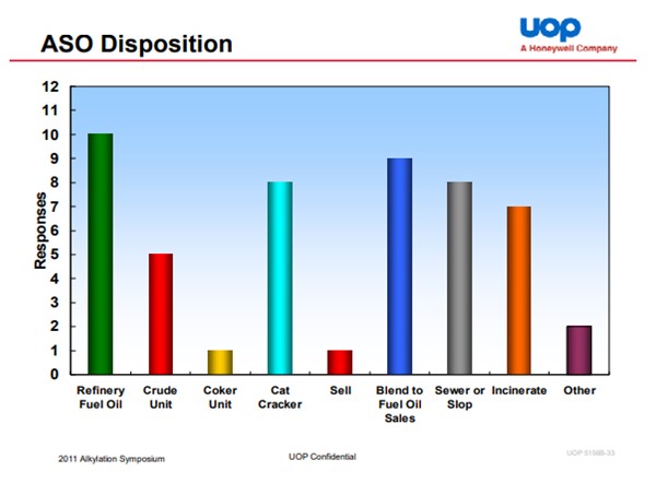
The summary response is: Collect the ASO, neutralize it in KOH or NaOH and then dispose of it in another refinery product stream. In our system, the most common destination for the ASO is FCC slurry oil, either in a separate rundown line to the tank or combined with the slurry oil rundown. It can be routed to other streams such as slop oil or crude. However, in these cases care must be taken relative to metallurgy in units where the material is processed as it can still contain some fluorides and other trace materials that could lead to issues. A key component, regardless of destination is to ensure good neutralization. We have sites that have utilized the licensor technology for ASO neutralization and others that have expanded on this. Separation of the KOH (or NaOH) prior to transfer of the neutralized ASO is also key. Using an additional separation or surge drum can be effective for this. In the 2011 UOP Alkylation Symposium earlier this year, UOP outlined an industry summary of ASO routing (see chart)
Regarding rerun or acid regenerators in batch or continuous mode, both batch and continuous rerun tower / acid regenerators are implemented at our sites. This is typically dependent on which heritage licensor designed the unit (Phillips or UOP). Some of our sites choose to run their continuous rerun columns in a batch mode, finding this to more effective from an overall operations or steady tower operation, then batch neutralizing and routing to eventual disposal destination. For those operating in batch mode a step to flush the ASO lines should be implemented after the ASO transfers. LCO is most effective due to its aromatic content. If a lighter stream is used consideration relative to product RVP / flash needs to be taken into account. Flushing of the ASO wash system lines is also appropriate as these are more typically operated in a batch mode.
Relative to system plugging, we have experienced line restrictions at several of our sites, primarily when the ASO rundown is combined with the FCC slurry oil rundown line to storage. At some locations a separate run-down line has been installed or utilized to alleviate this. KOH (or NaOH) carryover from the ASO washing system is thought to be one major contributor to this line plugging as the KOH, ASO and FCC catalyst fines in the slurry oil combine. One site has experienced plugging in the wash system. See previous comments online flushing.
Rate of transfer is typically on a batch basis when either the neutralizing drum or washer is at high level (or the downstream or upstream collection vessel is at high level). If there is adequate hold up time in these vessels, then transfer from the rerun system (or the feed to the rerun system) should not be limited by ASO disposal. If there is a step change increase in ASO production, then upstream unit operations should be carefully reviewed for items such as increased feed sulfur, moisture, diolefins, acid strength, I:O ratio or significant change in feed composition such as shifting to increased propylene or amylene.
Brad Palmer (ConocoPhillips)
UOP reported in their 2009 Alky Symposium the following industry wide acid soluble oil (ASO) dispositions: Fuel Oil/Sales 36%, Burn 20%, Slop 16%, FCC 13%, Crude 7%, and Coker 4%. The ASO is to be neutralized with KOH or NaOH with consideration given to how fluorides and potassium or sodium may impact the disposition of the ASO, especially if going to a catalyst process unit such as an FCC or hydrotreater.
The rerun tower should be operated continuous. Some sites run the tower bottom level control in a "gap" control mode, cycling the control valve between full open or full closed based on a low level of 30% and a high level of 70%. This "gap" control is to minimize valve wear if trying to throttle a small continuous flow of ASO. If the rerun tower is operated in batch mode then the lines need to be flushed between batches to avoid plugging.
Year
2011
Process