
Question 91: What are the characteristics of FCC catalyst to minimize particulate emissions at the stack?
John Aikman (Grace Catalysts Technologies)
While there are several operational and mechanical factors that can influence a unit’s particulate emissions, the question asks specifically about the FCC catalyst; as such, the following discussion will address characteristics of fresh catalyst only.
There are four basic characteristics of FCC catalyst that can have direct effects on particulate emissions. These same characteristics will also affect particulate losses to the fractionator and slurry product. The first characteristic is simply the amount of fines content coming into the unit with the fresh catalyst due to the manufacturing process. Figure 1 is an example of a typical fresh catalyst particle size distribution, with a theoretical depiction of a cyclone’s ability to retain fresh catalyst particles. DPTh is the smallest particle diameter which can reliably be collected by a cyclone and is used to model cyclone performance. Particles below this size will be lost by the cyclone.
A review of the Grace Ecat database showed that none of the FCCU’s in North America can retain any 0-20 μ range particles. In addition, they only retain an average of approximately 4.0 wt% in the 0-40 μrange. Fresh catalyst typically ranges anywhere from 9 to 16% of 0-40 μ depending on the supplier andmanufacturing process. Some units require higher amounts of 0-40 μ range particles to help with circulation.

The next characteristic of fresh catalyst that must be considered is the particle density. he DPTh mentioned above will decrease with increased catalyst particle density, per Equation 1 below. This means that cyclones can retain smaller particle sizes as the particle density increases. This is due to the centrifugal force acting on a heavier particle. However, particle density is not the same as apparent bulk density (ABD). Industry typically measures and reports ABD as part of the routine Ecat analysis, but this should not be mistaken for particle density for cyclone efficiency purposes. Since Al2O3 is denser than SiO2, catalysts with higher alumina content will have higher catalyst particle density.

The third characteristic is the inherent attrition resistance of the fresh catalyst. Industry measures the attrition resistance via a variety of tests, with the primary goal of providing a relative indication of catalyst attrition resistance. Grace utilizes the DI test or Davison Index. On the DI scale, a lower number is less likely to cause attrition and generate microfines. It is usually not valid to compare attrition resistance results obtained from different laboratories. Additionally, it is important to note that the energy applied to a catalyst sample during attrition testing is much more severe than commercial conditions.
As discussed above, the majority of the microfines created in the FCCU will leave the unit through either the reactor or regenerator cyclones, with the latter potentially contributing to increased particulate emissions at the stack.
'The attrition resistance of the catalyst is a function of the manufacturing process and the binder material utilized during the manufacturing process. Figure 2 is an example of how a refiner improved the FCCU stack opacity with catalyst formulation. The reduction was achieved changing to a Grace supplied catalyst with lower DI and lower 0-40 μ content in the fresh catalyst.

The final characteristic of fresh catalyst that affects particulate emissions is its morphology. Morphology can be defined as the study of the form and structure of a particle and its specific structural features. A catalyst particle that has a smoother exterior surface is less likely to generate microfines in an FCCU. Even catalysts with a low fresh DI measurement can cause increased particulate emissions if there are surface irregularities resulting from the manufacturing process. In order to demonstrate this visually, Figures 3 and 4 present SEM’s (scanning electron microscopy) of “bad” and “good” fresh catalyst morphology for a side-by-side comparison.
Figure 3 and 4 SEM’s of Fresh Catalyst (magnified X250)
“Bad Morphology” “Good Morphology” In conclusion, there are several characteristics of fresh catalyst that can be controlled to reduce particle losses and thereby reduce flue gas emissions. Specifically, to lower emissions the fresh FCCcatalyst should possess the following characteristics: a particle size distribution with an optimal range of 0-40 μ particles, higher catalyst particle density, lower DI, and superior morphology. Grace’s alumina-sol technology provides superior binding to the catalyst particle leading to best-in-industry attrition resistance. The versatility and performance of alumina-sol catalysts coupled with Grace’s manufacturing capability, have resulted in wide-market acceptance and as a result, Grace is the preferred FCC technology for loss sensitive units around the world.
Year
2014
Process
Question 92 What is the impact of high iron you have seen in some tight oil feeds? What level of Fe on the equilibrium catalyst causes problems, and what are the typical symptoms? What changes to FCC units hardware, catalyst and operation have you implemented to manage Fe poisoning? What is the impact of other uncommon contaminants such as K, Ca and Mg?
Ann Benoit (Grace Catalysts Technologies)
Tight oil feeds generally have high levels of iron and calcium present in them. Iron can have a negative effect on catalyst performance. While particulate tramp iron from rusting refinery equipment does not have a significant detrimental effect on catalyst, finely dispersed iron particles in feed (either as organic compounds or as colloidal inorganic particles) can deposit on the catalyst surface, reducing its effectiveness. The iron deposits combine with silica, calcium, sodium, and other contaminants to form low melting phases; which collapse the pore structure of the exterior surface, blocking molecules from entering the catalyst particle and reducing conversion. Iron, in combination with calcium and/or sodium, has a greater negative effect on catalyst performance than does iron alone.
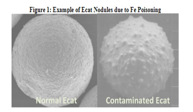
The symptoms of iron and calcium poisoning include a loss of buttons cracking and conversion as feed particles are blocked from entering the catalyst particle. In addition to a drop in conversion and a decline in bottoms cracking, poor catalyst circulation could be a symptom of poisoning. A potential indication of Fe poisoning is a drop in Ecat ABD. Nodule formation on the catalyst (shown in figure 1), due to the buildup of Fe on the surface, prevents the Ecat from packing as densely.
Grace has done extensive work on understanding how iron and calcium poisoning impact catalytic performance and has not seen any credible evidence of interparticle iron migration. On the contrary, all the evidence indicates iron poisoning results in a permanent degradation of the catalyst particle surface.
In evaluating the potential for iron poisoning, it is important to calculate the incremental iron from the feed, and not only assess the total iron level on Ecat. This is because different catalysts have different starting iron contents. A general rule of thumb is that performance could suffer with as little as 0.2 wt% incremental Fe, particularly for low alumina catalysts that are more prone to iron poisoning. The level, of course, is dependent upon factors such as the catalyst resistance to Fe poisoning and the concentration of alkali metals contaminants such as calcium and sodium.
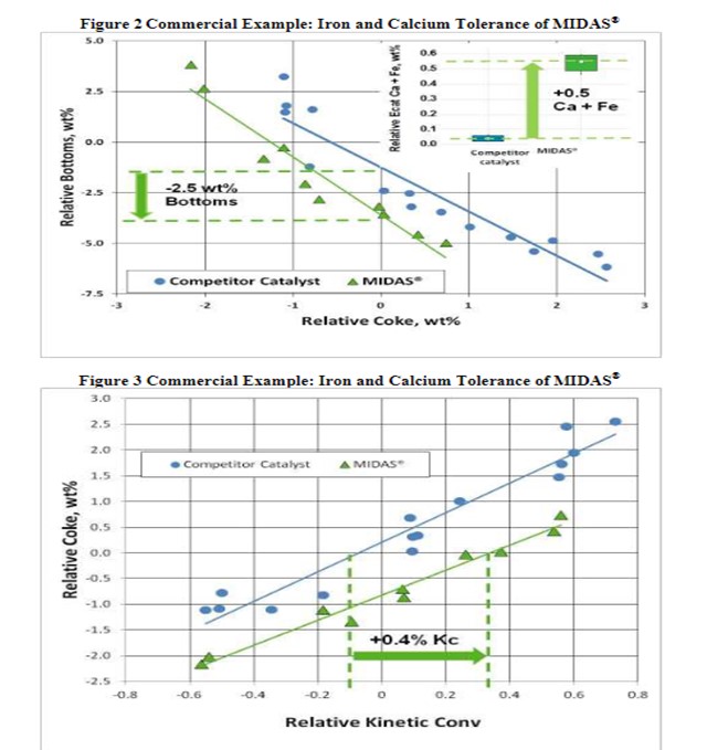
To manage iron poisoning, refiners should reformulate to more iron- resistant catalysts and consider higher, fresh catalyst additions. Catalyst design can be optimized to resist the effect of contaminant iron and calcium. High alumina catalyst, especially catalyst with alumina-based binders and matrices, such as Grace’s MIDAS® technology, are best suited to process iron- and calcium-containing feeds because they are more resistant to the formation of low-melting point phases that permanently destroy the surface pore structure. Optimum distribution of mesoporosity (pores in the 100--600Å size range) also plays a role in maintaining performance because diffusion to active sites remains unhindered, even with high levels of contaminant metals. One thing to consider, while two catalysts may have similar total pore volume, their mesoporosity can vary greatly. MIDAS® catalysts feature the highest levels of mesoporosity in the market.
The resistance of MIDAS® to iron and calcium poisoning was demonstrated in a commercial application (Figure 2 and Figure 3). A refinery was processing a feedstock high in iron and calcium. Over time, the unit exhibited the symptoms of iron poisoning. Iron nodules built up on the catalyst surface; equilibrium catalyst activity, unit conversion and bottoms cracking began to suffer. The catalyst was switched from a competitive catalyst to MIDAS®. Upon switching, activity, bottoms cracking, and coke selectivity improved despite the higher metal's levels.
With regard to other uncommon containments, alkali metals such as potassium can result in deactivation of the FCC catalyst, particularly under the oxidizing, high temperature conditions in the regenerator.
Alkali metals cause a loss in activity due to neutralization of acid sites. The result can be a loss of unit conversion. On a weight percentage on equilibrium catalyst basis, the deactivation effect of potassium is similar to that of sodium.5 Magnesium is not of concern at low levels (<0.5 wt%), but at higher levels, magnesium has a tendency to react with the silica from the zeolite to form forsterite (Mg2SiO4), which will decrease zeolite stability and adversely affect unit conversion.6 As mentioned above, calcium poisoning can be a serious problem, reducing bottoms cracking and catalyst activity. Like Fe, Ca deposits on the exterior surface of the catalyst,2 as calcium builds up on the surface, the particle becomes compromised, and this can result in unit conversion loss. In conclusion, catalyst reformulation (to more resistant formulas such as Midas®) and higher fresh catalyst additions to purge the contaminants from the inventory are effective strategies to recover from non-conventional contamination in the FCC unit.
Year
2014
Process
Question 94: To reduce the risk of igniting the gas mixture in the electrostatic precipitator (ESP), we are considering safety interlocks for de-energizing the ESP when carbon monoxide content gets too high. Please share your experience regarding (a) setting an appropriate trip point, (b) other interlocks to consider, and (c) advantages over operating procedures.
Jim Norton and Chris Steves (Norton Engineering)
Automatic trip points should be set so that the CO gas concentration is well below the Lower Explosive Limit (LEL). Consideration should also be given to adding interlocks to trip the ESP based on high concentrations of methane, especially if the ESP is downstream of a CO Boiler or if there are other potential sources of fuel gas/natural gas to the ESP (even during upset conditions). An automatic shutdown will provide a higher safety factor than relying on operating procedures.
Year
2014
Process
Question 96: What are the different methods you employ to increase C3 recovery? What are your typical C3 recovery improvements for these various methods?
Year
2014
Process
Question 97: What is your optimal pH for wet gas scrubber water and how is this maintained? What are the implications of too high or too low pH?
Jim Norton and Chris Steves (Norton Engineering)
The optimum pH for a wet gas scrubber treating FCC flue gas is 6.9 to 7.1. This pH is maintained by the controlled addition of sodium hydroxide. The flow rate of sodium hydroxide is usually set up with a cascaded set point from a pair of redundant pH probes. This optimum pH is based on operating with bisulfite buffering. At higher pH, caustic consumption will increase as CO2 will be neutralized in addition to SO2. It should be noted that sometimes it is necessary to operate at the high pH of the bicarbonate buffering point if there is high excess O2 in the FCC flue gas. Under oxidizing conditions, the bisulfite species is not stable. If on the other hand, the pH decreases, SO2 removal will decrease. The SO2 slip starts to increase significantly below a pH of 6.0. If this pH continues to drop, it will also contribute to accelerated corrosion.
Year
2014
Process