Question 75: What are the pros and cons of driving coke VCM (volatile combustible matter) to a low level? What are the lowest green coke VCM you have consistently achieved?
Rajkumar Ghosh (Indian Oil Corporation)
Volatile combustible material (VCM) is an important parameter of Petcoke. VCM is basically unconverted pitch in the coke. The metal and sulphur are controlled by the type of crudes processed, but VCM content of coke is mainly in the control of DCU operators. The obvious benefit of driving green coke VCM to a low level is more distillate yield and less coke yield. Each 1 wt% reduction in VCM could increase refinery GRM by 5 cents/bbl. Moreover, lower VCM implies a relatively harder coke and lesser generation of undesirable fines during the coke cutting. Our objective is to achieve the coke VCM in the lower range of around 9%wt. for fuel grade coke. Coker operating parameters such as coke drum overhead temperature, pressure, COT, recycle, coke drum cycle time and steam quench rate play prominent role in determining VCM in the coke. Some of the rule of thumb for Coker variable on coke VCM are:
• With each 5o C rise in coke drum vapour temperature, VCM in coke decreases by 1 wt%.
• Decreasing cycle time by 6 hrs, increases coke VCM by 1.0 wt%.
• 2-3o C increase in COT reduces coke VCM by 1 wt% Comparison of VCMs in 18hr and 24hr cycle is given below:

As a best practice for reducing coke VCM, we increase the COT by 2o C, an hour prior to drum switch. We continue with the higher temperature through the drum switch and get back to normal COT once the receiving drum top temperature reaches near normal value. Steaming of the offline drum is another factor that impacts VCM.
If the steaming of the offline drum is not done for sufficient time with sufficient amount of steam, this may contribute to an increase in VCM. The steaming amount depends on the drum diameter. For a typical 28 ft drum to a larger diameter drum i.e. 32 ft; steam flow is varied in the range of 15–18 MT/ hr. These figures have been arrived at based on our experience w.r.t. adequacy of Coke Bed cooling & VCM of the Coke. It was also observed that on reducing the amount of steam to around 10 MT/ hr, there was an increase in VCM of approx. 0.5-1 wt%.
Flip side of very low VCM is that the coke becomes very hard and coke cutting operation consumes longer time, resulting in delay in the coke drum cycle. Also, very hard coke (low Hardgrove Grindability Index, HGI) makes it difficult for the customer to crush and use and hence less acceptable to them.
Lowest level of coke VCM achieved at our Cokers is 8.5 to 9 wt%. Typical VCM level that we are achieving on sustained basis is around 9-10 wt%.
Jeff Lewellen (HollyFrontier)
I agree with the primary answer. For fuel grade cokers, optimizing VCM is primarily an economic decision balancing liquid yield with unit operation. Our approach to optimization is:
o First, optimize coke drum stripping steam volume and duration for recovery, and limited by drum and fractionator velocities and available cycle time.
o Second, target coil outlet temperature (COT) to minimize VCM while maintaining required drum cycles and heater run lengths.
Optimum VCM target is somewhat feed dependent with our normal range in the 8 – 10 wt% range.
Eberhard Lucke (Commonwealth E&C)
The drivers to lower the VCM of the green coke can vary depending on what kind of operation you run. Fuel grade coke operations typically don’t monitor VCM on a regular basis. The only advantage in lowering VCM would be to reduce the loss of very heavy gasoil material with the coke product. But the required measures to reduce VCM (longer steam stripping, more stripping steam, or higher coil outlet temperature etc) and associated cost most likely exceed the gains. In anode grade operation, the VCM has a direct relation to the vibrated bulk density (VBD) of the calcined coke and therefore, controlling and minimizing the VCM content of the green coke is crucial to a successful anode coke business. In the past we achieved best results by maintaining a rigorous steam stripping regiment and by implementing a temperature ramp function for the coil outlet temperature that allows to drive more volatile material out of the coke bed before the drum will be steam stripped. With all these measures in place we achieved consistently VCM values around 8wt% and consequently very good VBD results in the calcined coke. The price is a slightly higher energy consumption in the charge heater which can be compensated by further optimization of the control scheme for the coil outlet temperature. Other tests with lowering the drum operating pressure didn’t show the same effect and couldn’t be repeated on a consistent basis.
Year
2011
Process
Question 76: What can cause exothermic reactions in propylene driers and guard beds and how can these reactions be prevented?
Tom Lorsbach (UOP)
As introduction, Propylene Recovery Units downstream of FCC units typically consist of a C3/C4 Splitter, a Deethanizer and a C3 Splitter in series. The propylene from the C3 Splitter overhead is treated in regenerable molecular sieve Driers for moisture removal and finally passed through Guard Beds for trace contaminant removal. The principle trace contaminants being removed by the guard beds are carbonyl sulfide, arsine and phosphine. There are a variety of guard bed adsorbents that are used. Metal oxide bound on an alumina support is one type of adsorbent often used for trace contaminant removal. Occasionally hybrid type adsorbents are utilized (downstream of the driers) to remove trace levels of oxygenates, organic sulfur species and nitrogen compounds.
With regard to the molecular sieve driers, there is a small (10-15°F) adsorption exotherm when liquid propylene is first charged to the molecular sieve adsorbent. This small exotherm dissipates quickly as propylene flows through the drier beds. Exothermic runaways are unlikely on molecular sieve type moisture driers operating normally to remove dissolved moisture from liquid phase propylene. Elevated levels of diolefins, oxygenates or metals could potentially cause exotherms in the molecular sieve drier.
During start-up and operation of any adsorption system it is important to stay within the pressure and temperature limits set by the equipment and adsorbent manufacturers. Excessive temperatures can cause equipment failure and result in life-threatening fire or explosion. There are a number of factors that can cause excessive temperatures in adsorbent systems.
1. Introducing a flammable or reactive fluid into a vessel containing air.
2. Introducing a high concentration of a reactive, strongly adsorbed material into fresh or regenerated adsorbent. In applications where there is sufficiently high risk of thermal excursions a low reactivity adsorbent should be considered.
3. Using a highly reactive fluid to heat or cool the bed. Examples of reactive fluids would include ethylene, propylene and other olefins.
As mentioned above, when equipment and adsorbent operating guidelines are followed closely, there is normally a small adsorption exotherm during initial commissioning and this exotherm dissipates quickly as propylene flows through the drier beds.
There have been two incidents of uncontrolled exotherms occurring in FCC PRU adsorption beds.
1. In one case an operator changed the temperature permissive from 122°F to 338°F (50°C to 170°C) in the drier regeneration control system, allowing excessively hot propylene from the freshly regenerated drier vessel to enter the lead COS/Arsine guard bed vessel. The high temperature propylene initiated highly exothermic auto-reduction of the metal oxide to the elemental metal through both guard beds in series. The exotherm caused the paint to blister on the vessels and piping and the guard bed adsorbent was fused, but the system did not lose containment.
2. The second incident was more serious in that the vessel (containing stacked beds of two different adsorbents) lost containment. The vessel operated up flow. The inlet section of the adsorbent bed contained an adsorbent for removal of moisture and trace oxygenates. The exit section of the adsorbent bed contained adsorbent selective for the removal of COS. The investigation of this incident identified vapor phase propylene (instead of liquid phase propylene) being sent to the vessel for 67 minutes, with concomitant bed channeling, high heat of adsorption in the inlet section (where a reactive adsorbent was installed) and poor heat dissipation as the root cause of the failure. High local temperature and stresses exceeding the tensile strength of the vessel shell led to rupture of the shell near the end of the inlet section of adsorbent.
Dwight Agnello-Dean (BP)
Propylene is a reactive fluid and therefore a known exothermic reaction is propylene polymerization which can be catalyzed by the adsorbent material. Typically, these reactions are not significant and are not observed if the adsorbent material is proper for propylene use and the heat of adsorption during startup is adequately dissipated. At higher temperatures these reactions can accelerate rapidly.
Within our network there have been few reports of incidents involving propylene driers and the investigations of these events have not identified common root causes. Learning’s from these events include ensuring the proper adsorbent material is selected and that startup procedures include temperature increase limits with corrected actions if exceeded.
Year
2011
Process
Question 77: How prevalent is the use of low slide valve dP override control in modern FCCU DCS systems and can the over-ride be considered an "independent protection layer" (IPL) when conducting a layer of protection analysis (LOPA) to protect against a pressure reversal scenario?
Matthew Meyers (Western Refining)
The panel concluded that 100% of the FCC units in their respective companies used the low slide valve dP over-ride to protect against reversals. The consensus of the panel was that having dual slide valves did not significantly increase the reliability of the system. The IEC 61511, 2003 definition of an Independent Protective Layer is the following:
1. The system must have a risk reduction factor of at least 100 (10-2).
2. It must be designed to protect against a specific event
3. It must operate independently of other protective layers (i.e., No common causes of unavailability)
4. Must have an availability of 0.9 or greater
5. Must be testable
Since the typical slide valve DP override system shares the low signal selector algorithm in the DCS with the regulatory control system, it cannot meet the strict IEC definition of independence. The control algorithm (or changes thereof) itself may be a common cause of unavailability.
The probability of failure on demand (PFD) for the slide valve DP override system depends upon a number of factors:
• Standpipe fluidization and stability
• Redundancy of DP transmitter field-side: all process taps and tubing are independent with reliable purges
• Each transmitter configured to fail low and SIL rated to prevent incorrect configuration changes
• Wiring from each transmitter to the BPCS in separate home run cables with redundant inputs to the BPCS
• BPCS configured to fail low on loss of signal from either DP transmitter
• Constant slide valve modulation and testing with good slide valve maintenance
• Dual slide valve hydraulic pumps with separate motive force sources (e.g., electrical and pneumatic)
• Slide valve skid alarm instrumentation to ensure availability: reserve accumulator in service, reserve accumulator pressure, position deviation alarms, loss of tracking, loss of feedback, etc.
All of these factors should be carefully considered before determining a PFD. Assuming each item is properly maintained and suitably stable over the course of the operating history, a PFD of 10-2 is achievable.
In terms of conducting a LOPA, the slide valve DP override system may be used to reduce the impact event frequency and thereby possibly reduce the risk. This may or may not affect SIL requirements, depending on other layers of protection that may be taken into account and the refinery-specific risk ranking matrix.
Mike Teders (Valero)
Low slide valve DP over-ride is used in every one of the Valero FCC units where a slide valve is used to control the catalyst circulation. The low dP over-ride is DCS based in our FCC units and we consider them to be an effective form of process control. In addition, we are developing a prescriptive design standard for an independent FCC shutdown system for our FCC units. The standard includes protection against a catalyst reversal by using low slide valve differential pressure to trigger a slide valve closure and trip the unit into a shutdown. Our FCC shutdown system is intended to be independent from the DCS based over-ride and would qualify as an Independent Protection Layer (IPL). We would not consider the DCS based over-ride to be an Independent Protection Layer (IPL) against a catalyst reversal if one of the hazard scenarios in the Layer of Protection Analysis (LOPA) included loss of the DCS controls.
Year
2011
Process
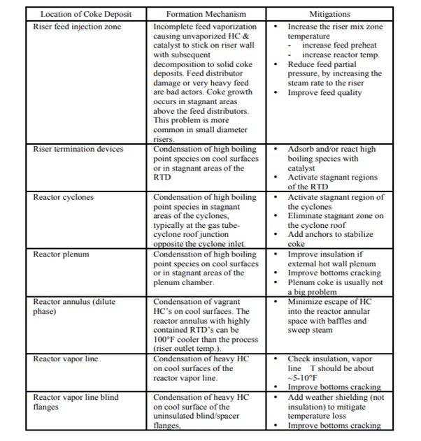
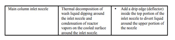
Question 78: What are the locations, formation mechanisms, mitigations and removal methods for coke deposition in the riser, reactor, reactor vapor line and main column inlet nozzle?
Tom Lorsbach (UOP)
There are two ways that coke forms in FCC reactors. These are incomplete vaporization in the feed injection zone of the riser and HC vapor condensation of high boiling point species on cooler surfaces. In both cases the hydrocarbon liquid wetted on a surface has essentially infinite residence time at elevated temperature, resulting in thermal degradation reactions that create solid coke deposits. Additionally, the heavy hydrocarbon wetted surfaces tend to be sticky and it is common to find high levels of catalyst incorporated into the coke deposits. Ash from reactor coke samples are often in the range of 20 - 50 wt%. The potential for coke formation in the reactor and riser increases as feed becomes heavier and more contaminated. In addition, different riser termination devices and arrangements of reactor internals will have differing susceptibility to coke deposition. Removal of coke from risers and reactors is performed by careful mechanical chipping. High pressure water jetting has been used successfully to remove coke from reactor vapor lines.
The chart below summarizes the locations, formation mechanisms and possible mitigations of coke formation in FCC reactors.
Mike Teders (Valero)
Location:
Coke found in the riser and reactor cyclones is a symptom of poor feed nozzle performance, where un-vaporized feed is subjected to high temperatures and thermally decomposes to coke. Coke found in the reactor is most likely due to inadequate dome steam used to blanket the reactor to prevent accumulation of vapor products from condensing and coking on lower temperature surfaces. Coke found in the reactor vapor line is most likely due to condensation of high molecular weight vapor at low temperature surfaces such as vapor line supports and main column nozzle attachments.
Formation Mechanism:
Coke is deposited in the FCC reactor section by a thermal process, where the raw feed has either failed to completely vaporize and participate in the catalytic cracking reaction or the high molecular weight vapor has condensed on a surface where it thermally decomposes to coke.
Mitigation:
Mitigation of coke from un-vaporized feed can be done by elevating the raw oil feed temperature to improve the feed nozzle performance. (Typically, the best practice is to limit the feed temperature in resid FCC units to no less than 425 F to ensure adequate feed vaporization.) Feed nozzle technology also plays a role in resid feed vaporization, requiring a robust design that delivers good atomization and catalyst penetration. Mitigation of coke in the reactor is accomplished from maintaining the minimum dome steam rate recommended by the technology provider (typical superficial velocity is 0.05 to 0.1 fps). Adequate insulation and weather protection on hot reactor and reactor vapor line services is also a good best practice for mitigating the formation of coke. At one location we have experienced coking in the reactor vapor line at vapor line pipe support. The support ring was a “cooling fin”, causing the condensation of high molecular weight vapor and ultimately coking. The ring was not insulated since the mechanical engineers felt that the elevated support temperature would derate the strength of the support ring. The support ring was shielded from rain by installing insulation weather protection. We also have experience with hydrotreating FCC feed making less coke in the reactor than unhydrotreated feeds. At one location we avoid low reactor temperature since experience has shown this to cause coking in the reactor cyclones. The coke formation in the low reactor temperature case is most likely caused by unvaporized high molecular weight feed.
Removal:
Not all coke is removed. Some coke is retained if it is not disruptive to the normal flow path. Coke removal is a manual operation using chipping hammers for the hard coke. In cold wall designs, the coke impregnated refractory can be indistinguishable from hard coke. If the refractory contains stainless steel needles, the chipping hammer will throw sparks when the hammer tip hits the refractory, an indication to the chipping hammer operator to stop before significant refractory is removed. We hydroblasted coke from the Main Column nozzle where the reactor vapor line enters the tower. To my knowledge we have not used any unconventional methods to remove coke.
Year
2011
Process

Question 90: Do you have experience with slide/plug valve independent movements without any controller action?
Matthew Meyers (Western Refining)
There are 5 categories of initial causes which may lead to erratic slide valve movements in auto mode. These are oil contamination, servo valve amplifier tuning, part failure, mechanical linkages, and electrical connections. Oil contamination is the initial cause a vast majority of the time.
Oil must be kept very clean at all times. From pre-commissioning to start-up, the fluid must be maintained at a spec equal to or better than ISO 14/11. This spec allows that only 80-160 particles per mL are between 6 and 14 microns in diameter and that only 10 – 20 particles per mL are greater than 14 microns in diameter. If this spec is not maintained, contamination may occur including particulate silt or chips arising from two or three body interactions and stress raisers caused by particle collisions. In addition, free or dissolved water and air may create more particles through corrosion. The wear resulting on the servo valve itself may cause the valve to stick and chatter. The clearance of the servo valve is only 1 to 5 microns.
The servo valve amplifier may require re-tuning. The gain may be too high or low, the servo dither may be set too high, the servo balance may be offset, or the amplifier may need recalibration altogether.
The transducer at the end of the hydraulic cylinder may fail, causing the amplifier to lose feedback position of the slide valve. If this occurs, the DCS will also likely lose indication since the amplifier also relays the position indication to the DCS.
Any loose mechanical linkages or electrical connections may also cause unstable auto control. In this case, tighten all electrical connections and make sure there are no loose mechanical linkages.
Dwight Agnello-Dean (BP)
Our more common issues are lack of slide valve movement with controller action. We have had slide valves have move seemingly independent of controller action. Leaks in the hydraulic lines and failure of the servomechanism have been identified as primary causes.
Year
2011
Process
Question 89: Are there advances in cyclone lining material or cyclone designs to make them more erosion resistant allowing higher cyclone velocity or longer run lengths?
Mike Teders (Valero)
We limit the regenerator cyclone inlet velocity to 75 fps to make 4 – 5 year runs between turnarounds. Reactor cyclone inlet velocity limit is 80 fps if there is a riser termination device that reduces the catalyst loading to the cyclones. The hex mesh cyclone lining orientation, control of water addition and ramming techniques are key variables to erosion resistance. Hex mesh lining should be strength welded to the base metal and oriented in the opposite direction of flow as long as it can be securely welded to the base metal. Hex provides a better anchoring system than single anchors such as S Bars. Shop applied refractory can have 20 – 30% more hardness than field applied refractory. Valero has a refractory subject matter expert who carefully monitors as-installed physical properties and maintains communication with both installers and suppliers to ensure that both understand that the objective is to achieve the best possible abrasion resistance and the lowest possible shrinkage. Special refractory inspectors are used to monitor the refractory application process to get the best results.
Tom Lorsbach (UOP)
There haven’t been any breakthroughs or big step changes in cyclone lining materials. There have been a number of incremental improvements over the past 10 years or so.
1. Over the years the abrasion resistant lining materials have generally become more erosion resistant. Testing by ASTM C704 (Abrasion Resistance of Refractory Materials) show an improving loss trend, going from 5 - 6 cm3 to 3 cm3.2.
2. with increased FCC unit run lengths the cyclone abrasion resistant lining thickness has typically been increased from 3/4” to 1”.
3. Hexmesh should be rolled the easy way in cyclone inlets, barrels and main cones to avoid having the hex ribbons running parallel to the direction of gas and catalyst flow. This avoids presenting double thicknesses of hex metal (where the metal ribbons are clenched together) which are more susceptible to metal erosion.
4. Some refiners have used additional thicknesses of lining in problematic areas of the cyclone, e.g., at least one refiner uses 3” thick abrasion resistant linings in cyclone dust bowl cones and the upper section of the diplegs.
5. UOP now specifies 2” thick abrasion resistant linings in cyclone dust bowls and dust bowl cones.
6. The use of fully lined diplegs is also becoming more common with the extension of FCC run lengths to 6 or even 7 years.
7. Cyclone designs are evolving with a trend to longer cyclones and longer dust pots.
8. One cyclone vendor designs a sub-hopper below the conventional dust bowl to better contain the gas vortex and to mitigate erosion and catalyst re-entrainment.
Year
2011
Process