


Question 8: How do you improve cold flow properties in a hydrocracker?
LEICHTY (Chevron USA, Inc.)
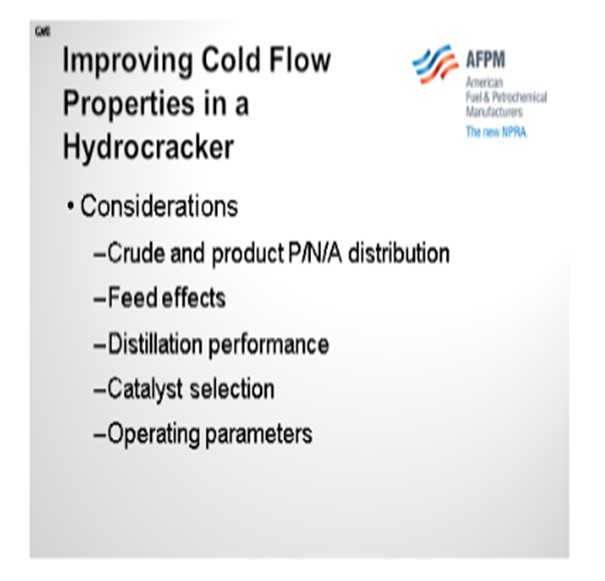
I will discuss several considerations including crude and product PNA distribution, feed effects, distillation performance, catalyst selection, and operating parameters.
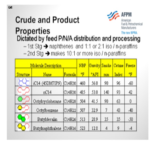
If you take a look at the molecular structure and properties of hydrocarbons in the C14 series, you will notice that the n-paraffins have the worst cold flow properties. Some of the multi-ring aromatics are also not good. So, when looking at crude purchases, waxy Far East crudes or some of the new shale-derived crudes will have worse cold flow properties because there are more paraffins in the feed. Moreover, any overlap in the feed (material that boils below the recycle cutpoint) will negatively impact cold flow properties since overlap material will contain more n-paraffins than the hydrocracked products. Finally, the proportion of product generated by the first stage versus second stage will also have an impact on cold flow properties. This is because the first-stage hydrocracker product tends to be 1:1 or 2:1 isoparaffin-to-normal paraffin ratio, whereas second-stage products can make 10:1 iso-to-normal paraffin ratio or better. Obviously, the more isomerization you get, the better your properties will be.
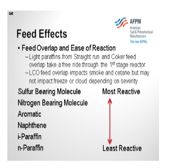
Now let’s consider feed overlap and ease of reaction. Light paraffins from straight run and coker feed, whether they boil below or above the recycle cutpoint, will tend to take a free ride through the first-stage reactor because they are the least reactive molecules and will negatively impact product cold properties. LCO feed overlap will impact the gravity, smoke, and cetane, but it may not impact the freeze or cloud, depending on the recycle cutpoint and the degree of saturation.
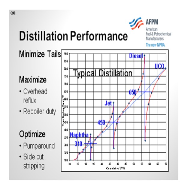
Distillation performance is probably one of the single biggest killers of cold flow properties. The cumulative distillation diagram below helps illustrate how the heavy tail of a distilled product can affect the cold properties. Cloud point and freeze point are defined by the temperature at which the first crystals of wax form in a hydrocarbon mixture as it is cooled. Sloppy distillation results in long tails which have material that will crystallize at a higher temperature. It is therefore important to have sharp distillation cuts by maximizing overhead reflux and minimizing pumparound in order to achieve high liquid-to-vapor ratio in the distillation tower. Note that it is also important to maximize reboiler duty in order to strip out the material boiling below the recycle cutpoint (the cutpoint between diesel and unconverted oil). The diagram shows approximately 5% yield that is boiling below the recycle cutpoint in the unconverted oil. With better stripping, much of this material could be recovered as on-spec diesel instead of cracked into less valuable products.
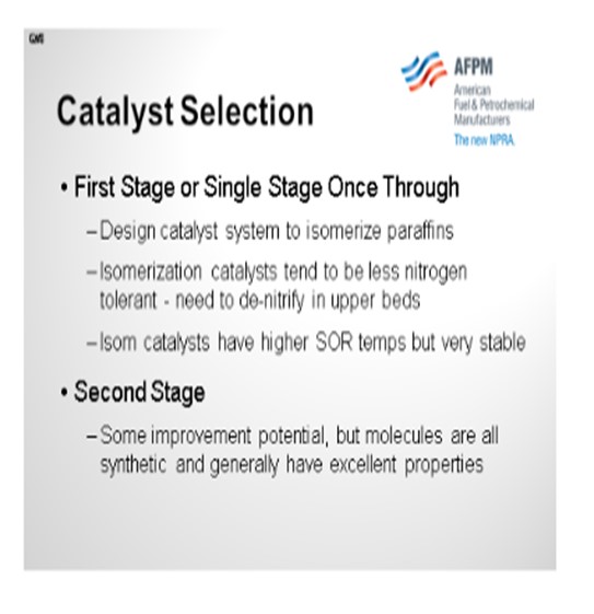
In your catalyst selection, if you have a single-stage hydrocracker, you want to design your catalyst system to isomerize paraffins to the highest degree possible. These types of hydrocracking catalysts tend to be a little less nitrogen-tolerant, so it is important to do good denitrification on the upper beds. The latest generation catalysts have higher start-of-run temperatures but have proven to be very stable over time. In the second-stage of a two-stage hydrocracker, there is not much room to improve cold properties since all of these molecules are synthetic in nature and have greater than 10:1 iso-to-normal ratio.
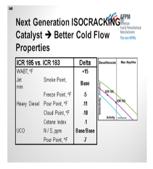
On this slide is a diagram showing how if you move from a conventional first-stage hydrocracking catalyst up to a newer generation that has a higher selectivity, you may require a little higher temperature in order to get the pour and cloud point reduction. The good news is that these newer generation catalysts are very stable, so you will not see a high degree of fouling over time.
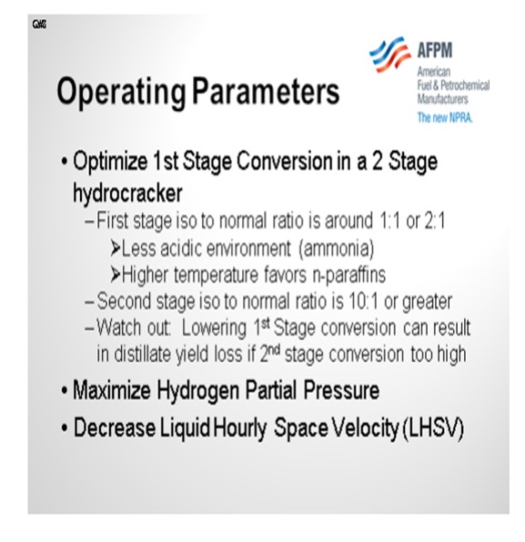
In the two-stage hydrocracker, it is important to optimize first-stage conversion. The first-stage products see a less acidic environment because of the presence of ammonia and higher temperatures. These conditions tend to favor n-paraffin production. Knowing this, it would be tempting to shift the first-stage conversion to the second stage by loading less hydrocracking catalyst in the first stage. However, in doing so, the per-pass conversion in the second stage could get so high that over-cracking will cause a reduction in distillate yield. Maximizing distillate with the desired cold flow properties therefore requires an optimization between first- and second-stage hydrocracker conversions. In any scenario, it is desirable to maximize hydrogen partial pressure and/or minimize space velocity in order to saturate diaromatics, promote cracking and isomerization, and achieve high distillate yield with good cold properties.
CARLSON (Criterion Catalysts & Technologies)
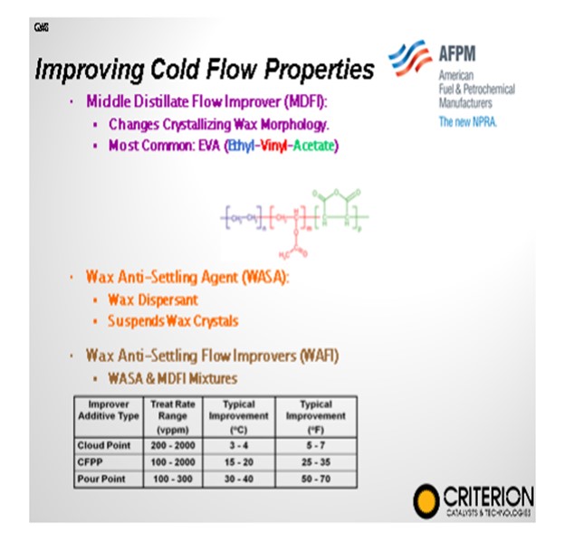
In addition to those considerations just presented, we look at middle distillate flow improvers and wax anti-settling agents. They can be effective, of course, in controlling pour point and CFPP (cold flow plugging properties), but they do not tend to help us much on cloud point. Neither of them adds to our operating cost. So, if we want to achieve significant cold flow improvement, we really need to know how to get rid of these long linear paraffins in the reactors.
To achieve a considerable improvement in cloud point, there is a need to remove the components causing the high cloud point. As discussed, reducing the feed final boiling point can reduce these components, but it can result in yield losses that may be economically unfavorable. A better approach is to install catalysts that can modify or remove the linear paraffins within the feedstock (dewax) while achieving the desired product selectivity.
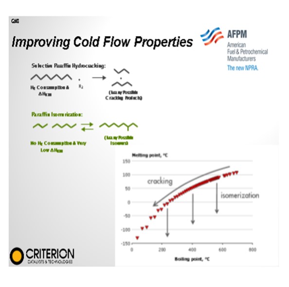
Two types of reactions are used for the removal of linear paraffins: selective paraffin hydrocracking and paraffin isomerization. Cracking decreases both the melting and the boiling point, while isomerization mostly affects the melting point, leaving the boiling point largely intact. Cracking creates two smaller fragments from the original linear chain paraffin molecule that have substantially lower melting points. However, the boiling point will also shift downward, potentially moving the molecules out of the target boiling range and reducing the total diesel yield. This yield shift can occur when using conventional zeolites in hydrocracking operations.
I
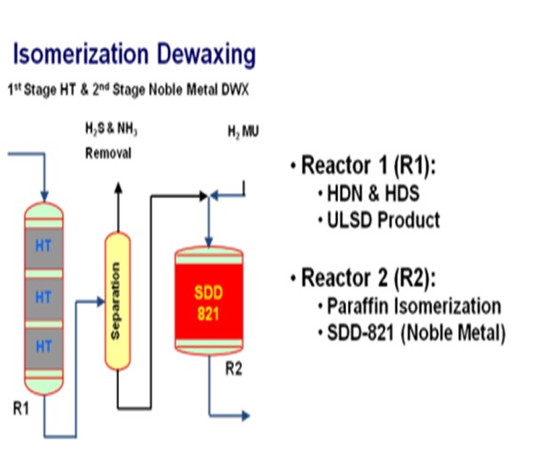
somerization, as you heard, would be a preferred mechanism because it both improves the cold flow properties by lowering the melting point and it leaves the final molecule in the distillate boiling range. However, selective isomerization is difficult to do in hydrocracking applications. Selective isomerization is typically much more favorable in a clean second-stage reactor with platinum or palladium-type catalysts.
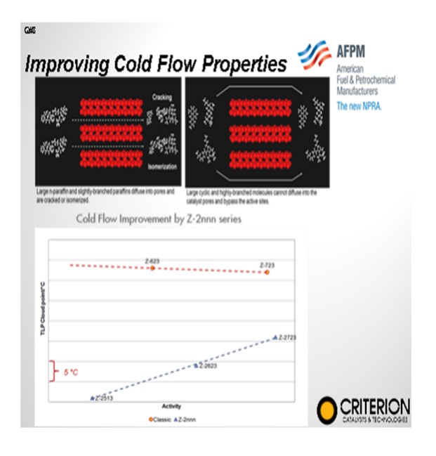
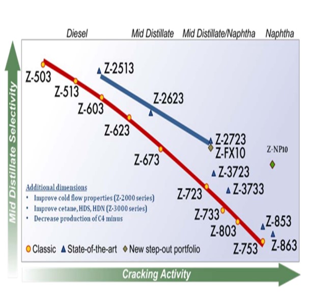
Effective dewaxing requires a proper differentiation between the linear paraffinic molecules (wax) and the rest of the feed molecules in order to achieve a high selectivity and minimize distillate yield loss. In hydrocracking, this is achieved by employing a shape-selective zeolite to preferentially convert the large linear paraffins. Criterion/Zeolyst has a portfolio of shape-selective cracking catalysts, its Z-2000 series, that selectively crack large linear paraffins resulting in an improvement in the product cloud point all along the activity/selectivity scale. These catalysts provide a boost in middle distillate yield versus conventional wide-pore zeolite catalysts due to the fact that the converted material has the tendency to reside in the distillate boiling range.
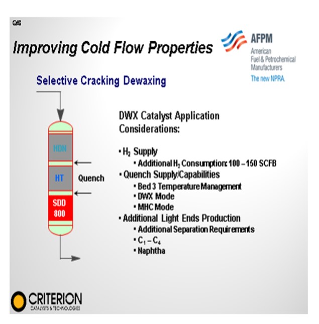
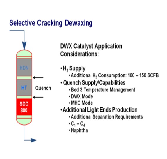
In mild hydrocracking operations, catalytic dewaxing can be employed on the backend of the upgrading process once all other properties have been already achieved. Criterion has a number of distillate feed applications where a catalyst, such as an SDD-800, can be loaded in the last bed of the reactor to assist in improving cloud point and, again, minimize distillate losses.
KEVIN CARLSON and WARD KOESTER (Criterion Catalysts & Technologies)
In the last decade, improving the cold flow properties of various feedstocks in a selective and cost-efficient way has gained increasing importance. In addition to providing a product in the specified cold flow property range, refineries apply cold flow improvement processes to avoid using cold flow additives, to reduce their kerosene blending requirements, to upgrade heavier feedstocks with higher cloud and/or pour points, and to create room in the blending pool for heavier feeds. The growing interest in cold flow improvement technologies stems from the increasingly stringent engine specifications, the processing of more paraffinic crudes, and the desire to sell the products at markets with demanding cold flow properties specifications.
There are several routes to improve the cold flow properties of distillates from a hydrocracker. Dilution by the addition of kerosene and/or cold flow improvers to the diesel pool have been the most widely applied routes. These methods are effective for pour point and cold filter plugging point (CFPP), but these have little effect on cloud point.
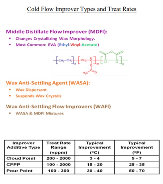
Cloud point measurement is aimed at registering the first appearance of solid particles and the additives/diluents used for improving the flow will not prevent the crystallization; rather, they delay it by modifying the shape of the crystals or by impeding their growth. Therefore, to achieve a considerable improvement in cloud point, there is a need to remove the components that cause the high cloud point. Reducing the feed final boiling point can achieve this with limited effect, but this results in relatively large yield losses that may be economically unfavorable. A better approach is to install catalysts that can modify or remove the linear paraffins within the feedstock (dewax) while achieving the desired product selectivity.
Two types of reactions are used for the removal of linear paraffins during catalytic dewaxing to improve the cold flow properties of the diesel: cracking and isomerization (selective paraffin hydrocracking and paraffin isomerization).
Cracking decreases both the melting and the boiling point, while isomerization mostly affects the melting point leaving the boiling point largely intact. Cracking creates two smaller fragments from the original linear chain paraffin molecule. These fragments have substantially lower melting point than the starting molecule and the cold flow properties, especially the cloud point, will drastically improve. However, the boiling point will also shift downward, potentially moving the molecules out of the target boiling range of the feedstock, reducing the total diesel yield. This is what can occur when using conventional zeolites in hydrocracking.
Isomerization is the preferred mechanism for converting linear paraffins because isomerized products have the same molecular weight as their parent starting molecules thus preserving yield. However, you cannot do selective isomerization under hydrocracking conditions with base metal catalysts. Selective isomerization is much more favorable in a clean second-stage environment (i.e., with very little to no H2S, NH3, unconverted organic nitrogen and sulfur-containing molecules) with employment of noble metals such as Pt (platinum) or Pd (palladium).
Effective dewaxing requires a proper differentiation between the linear paraffinic molecules (wax) and the rest of the feed molecules in order to achieve a high selectivity and to minimize distillate yield loss.
In hydrocracking, this can be achieved by employing a shape selective zeolite as the active acidic component to preferentially convert large linear paraffins. Criterion/Zeolyst has a Z-2000 series of shape selective cracking catalysts that selectively crack large linear paraffins resulting in an improvement in the product cloud point all along the activity/selectivity scale. These catalysts provide a boost in middle distillate yield versus conventional wide-pore zeolite catalysts due to the fact that the converted material has the tendency to remain in the distillate boiling range.
In mild hydrocracking applications, catalytic dewaxing can be employed at the back end of the upgrading process, where all other properties of the product (i.e., sulfur, nitrogen, aromatic content and cetane index) have already achieved the required target levels. Criterion has a number of distillate feed applications where a dewaxing catalyst, such as Criterion’s SDD-800, is loaded in the last bed of a single stage mild hydrocracker to improve cloud point while minimizing distillate yield loss.
BODOLUS (CVR Energy)
Start with catalyst vendors for recent developments in their products and capabilities. Cold flow properties are a very complicated function of catalytic selectivity. Our refineries adjust cold flow properties seasonally at the crude unit via distillation specifications and monitoring run-down tank samples. No daily or seasonal adjustments are made to the hydrotreaters/hydrocrackers for cold flow parameters. Once the catalyst selection is made, the hydrotreating and fractionation is done to accommodate distillation, flash and sulfur targets. A point worth mentioning in our system is the rationalization of the economic interactions between competitive distillate products in the finished product pool. The desire to produce high margin seasonal products (#1 kero) or solvents (mineral spirits) often impact or overly constrain the diesel cold flow properties adjustments made at the crude units.
SUBHASH SINGHAL (Kuwait National Petroleum Company)
The easiest way to achieve better cloud point/CFPP could be to adjust fractionator operations to drop some heavy kerosene to diesel inside the column (within flashpoint specs limits).
Year
2012
Process
Question 15: What can be done to mitigate foaming and emulsion formation in our hydrotreater high pressure separator? Is there any favorable experience with injection of antifoam/chemical emulsion breaker?
ROBERTSON (AFPM)
Since we only have about 40 minutes left to get through 12 questions, we are going to just take primary answers now. The secondary and third answers are in the Answer Book.
OHMES (KBC Advanced Technologies, Inc.)
We are starting to hear about more foaming problems, particularly with some of the unconventional or shale crudes being processed, and there are a few other instances. First of all, I will admit that a lot of these were covered in the early 1990s in the NPRA Q&A, and I shamelessly borrowed from them, noting that I had done so. Also, there was a really excellent article by Turner et al from Marathon that discussed the problems they had and how they went about to solving them. Obviously, we have run into a few of these issues as we have talked with clients.
So just briefly, refiners are typically finding some amount of foaming occurring. One will normally see either some liquid carryover, problems with level control where you are not truly seeing the level itself, and/or a lot of hydrogen under carry. I will skip most of these slides since I already touched on them.
Ultimately, the problem is really around separation. Maybe you have expanded the unit and did not take a look at the separator, thinking it would be okay when, in actuality, it did not have the capability for good separation. There are a few other problems people have seen, particularly if they have a recycle hydrocracker with a lot of HPNA, such that foaming will occur. As an example, Marathon has units processing feeds with high asphaltenes, particularly those with DAO (deasphalted oil). Another minor problem we have heard is that several people changed the process chemistry of their washwater and were getting some chemicals that were causing some foaming. Exchanger leaks can cause this, obviously, if you are running higher temperatures.
What are some options that you can use to fix this problem? First of all, we would start looking at your plant data. If you see a lot of hydrogen under carry showing up downstream in your separators, fractionator, or stripper, you can compare that quantity to what the thermodynamics will tell you to determine if there is an opportunity to not only stop the foaming, but maybe also recover some hydrogen. You could do some sampling to check the leaks. But honestly, what most people have had to do to isolate the problem is just do some test runs, pull out feed to check for a hydraulic issue, and play with some of the individual feeds, whether they are DAO or not.
So a few of the mitigation options: There are chemicals available, and we have seen people use them. To be honest, it is a bit hit-and-miss. For the ones who have been successful in using chemicals, their use is normally a short-term gap to get them through to a shutdown in order to fix the separator. From most of what we have seen, people have either had to replace or revamp the separator.
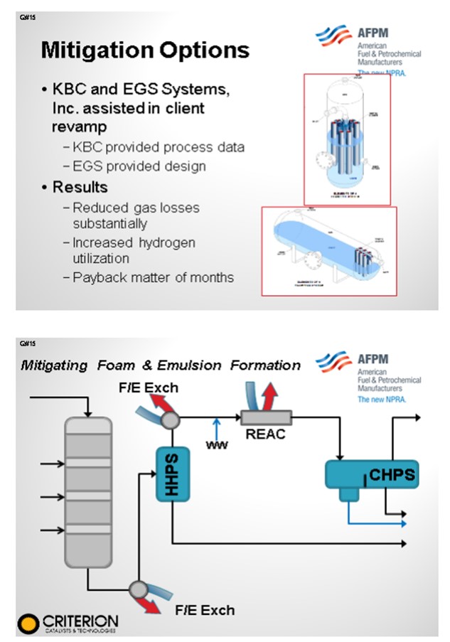
One example occurred when we worked with a company by the name of EGS. They design and manufacture Vortex Tube Clusters, which are a variant of a hydroclone. Although it is a little hard to see on the diagram, these tubes basically sit down within the liquid, which forces the vapors to go through the tubes. By going up and through the tubes, the emulsion is broken, thereby giving you the benefit of not only minimizing the foaming but also reducing the hydrogen undercarry. So with this particular client, we provided some of the process data because we were doing unit operability improvement work; EGS developed the revamped design. The client saw such a significant reduction in the gas losses that they were able to increase severity and throughput, thereby reliving the hydrogen constraint. So to summarize: Look at your plant data, and do some test runs. But for all intents and purposes, you are probably going to have to do some type of a modification to your separation equipment.
CARLSON (Criterion Catalysts & Technologies)
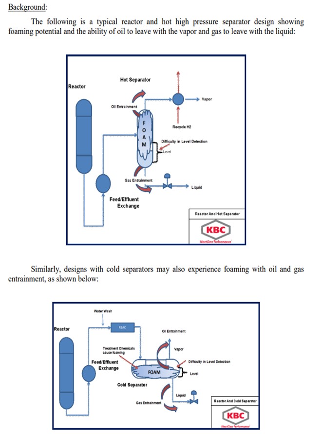
This phenomenon has tended to be observed with hydrotreater multistage recovery section designs when a change in the hot high-pressure separator (HHPS) operating condition led to a foaming/level control problems in the cold high-pressure separator (CHPS). When observed, the foaming in the CHPS appears to be very sensitive to the temperature at which the HHPS is operated at with foaming indicated above a particular range. This is most likely due to a change in the vapor liquid equilibrium or possible entrainment resulting in heavier than expected material being routed to the CHPS resulting in a tighter HC/H2O emulsion forming after injection of the washwater. The higher HHPS operating temperatures leading to this problem may have been due to operating the reactors at a higher EOR temperature or from fouling in the F/E (feed/effluent) exchangers. This issue can often be mitigated by the cleaning of F/E exchanger and somewhat managed by a modified descending quenching strategy of the catalyst beds.
OHMES (KBC Advanced Technologies, Inc.) and DAVID LEAKE (EGS Systems, Inc.)
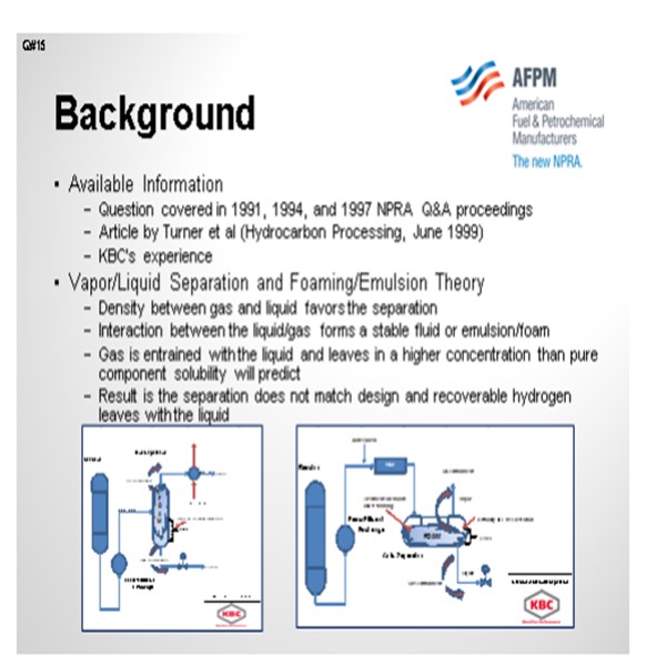
These particular questions were addressed in the early to mid-1990s NPRA Q&A sessions, specifically 1991, 1994, and 1997. In addition, an article was published in 1999 by Turner, et al that addressed the issue of foaming and emulsions (Hydrocarbon Processing, June 1999). The following response includes the information from those sources, as well as KBC’s experience in dealing with foaming and emulsion problems in hydroprocessing units.
Separator designs assume gravity separation and residence time will be sufficient to separate gas and liquid. The following is a brief description of the design process:
• Density between gas and liquid favors the separation.
• Interaction between the liquid and gas forms a stable fluid or emulsion/foam.
• Gas is entrained with the liquid and leaves in a higher concentration than pure component solubility will predict.
• The result is the separation that does not match design and recoverable hydrogen leaves with the liquid.
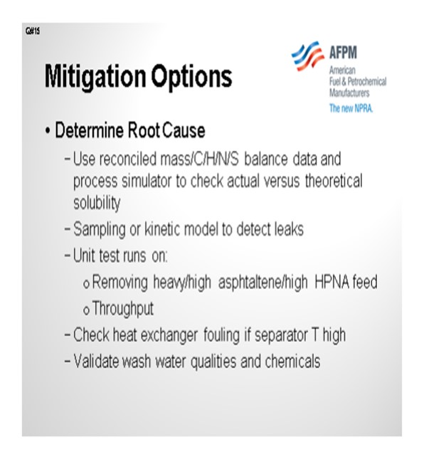
Causes and Indicators of Foaming and Emulsions:
Based on these information sources and KBC’s own experience in this area, the following are the causes of foaming and/or emulsions in high pressure separators:
• Hot Separators
o Inadequate separation capability increases with throughput or recycle gas rate,
o High content of polynuclear aromatics (PNAs) in hydrocracking seems to form stable emulsions, and
o High asphaltenes in feed, particularly when processing deasphalted oil (DAO) or resid.
• Cold Separators
o Chemicals in injected washwater,
o Exchanger leaks, and
o High temperatures in separator.
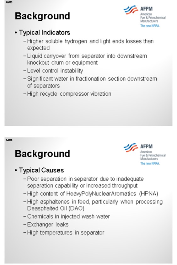
The typical indicators that a unit is experiencing foaming or emulsion problems are:
• Hot Separators
o Higher than expected hydrogen and light ends losses,
o Liquid carryover from separator into downstream exchangers resulting in loss of heat transfer, and
o Level control instability.
• Cold Separators
o Level control instability,
o Significant water in fractionation section downstream of separators, and
o High recycle compressor vibration.
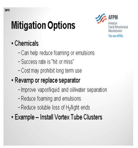
Mitigation Options:
Prior to selecting a mitigation method, the refiner determines the root cause of the problem or at least narrows down the list of potential causes. The first indication is that the fractionator or stripper off gas hydrogen content is much higher than design. This situation also can cause the fuel gas amine absorber to become over-loaded. Recycle gas flow is less than design and heat is lost in the feed/gas exchangers leading to over-firing of the charge heaters.
To determine if hydrogen and light ends soluble losses are high, the reconciled mass balance and elemental balances (carbon/hydrogen/sulfur/nitrogen) are compared to a simulation of the unit’s light ends and hydrogen loss. If the actual losses are significantly higher than the value based on thermodynamics, then the separator likely has a problem, and the potential improvement value can be calculated. This same approach, when accompanied by a kinetic model and some select sampling of additional unit streams, can help validate if exchanger leaks are occurring.
For validating potential causes such as operating conditions or feedstock type, a series of short-term test runs can be completed. If the unit is processing a new high asphaltene content feed, then removing the feedstock may reduce the foaming. Of course, replacing the feedstock to maintain relatively constant unit throughput will allow verification of feedstock type versus throughput as a cause. Upstream fouling of exchangers may be leading to elevated separator temperature, such that the remedy is exchanger cleaning rather than a unit modification. Finally, washwater quality and source should be validated to ensure that unknown chemicals are not being injected into the water and driving the foaming or emulsions.
Chemical addition to improve foaming or break emulsions are an option. However, based on the past NPRA responses and KBC’s experience, the success rate is “hit or miss”. Those units that have had success are able to properly disperse the chemicals in the separator to achieve the desired improvement, so some type of an injection system will be needed. A short test run with chemical injection may give a preliminary indication of improvement. Most users have avoided chemicals as a long-term solution due to the typical costs.
The most successful mitigation of foaming and emulsions is to improve the separator through revamp or replacement. KBC has direct experience with such a modification. For a client who was experiencing significant separation problems in a resid hydroprocessing unit, KBC partnered with EGS Systems, Inc. to revamp a high pressure separator, with KBC providing the necessary process data and EGS providing the design. The primary revamp involved installation of vortex tube clusters (inlet defoamer) internals. The advantage of these designs is no change is made to the high pressure containment vessel. The cyclones are internally supported, and no attachment welds are required.
The following schematics, courtesy of EGS Systems, Inc., provide generic examples of these vortex tube clusters installed in a horizontal and vertical separator.
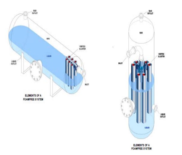
For this particular installation, the revamp greatly improved separation, such that the entrained gas losses decreased dramatically and unit hydrogen utilization increased. Therefore, the economics payback was a matter of months, not including the impact of foaming and emulsion reduction. KBC’s experience is foaming and emulsion problems require some modification or upgrade to the high pressure separators to improve oil/water and vapor/liquid separation. As a final note, foaming in the amine contactor within the high pressure loop was excluded from this response, as this topic has been covered extensively in past NPRA proceedings.
Year
2012
Process
Question 9: What do the possible causes of high pressure drop in lower beds of HT (hydrotreater) and HC (hydrocracker) units? What techniques are used to diagnose the causes prior to shut down? Are there any mitigation techniques or strategies to extend the cycle?
LEICHTY (Chevron USA, Inc.)
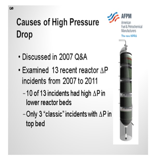
The topic of the causes of high-pressure drop was discussed in the 2007 Q&A, so you may want to refer to that transcript for additional information. At Chevron, we had a string of 13 reactor ΔP (pressure differential) incidents between 2007 and 2011. Ten of these occurred in lower reactor beds with only three of them being classic top bed ΔP incidents.
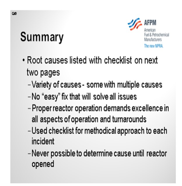
The root causes are listed in a table included with my Answer Book response. To save time, I am not going to go through each one in detail. There are a wide variety of causes for these incidents; and in some cases, multiple causes. This list shows you that there is no easy fix that will solve all of the issues. Rather, there are many steps that must be done with excellence in order to avoid ΔP issues, especially in the planning and execution of turnarounds. A checklist was developed in order to methodically approach and analyze each incident. It was also used to devise action plans to avoid future incidents. In all of our incidents, it was impossible to determine the exact root cause until the reactor was opened and inspected. Basically, we were surprised every time.
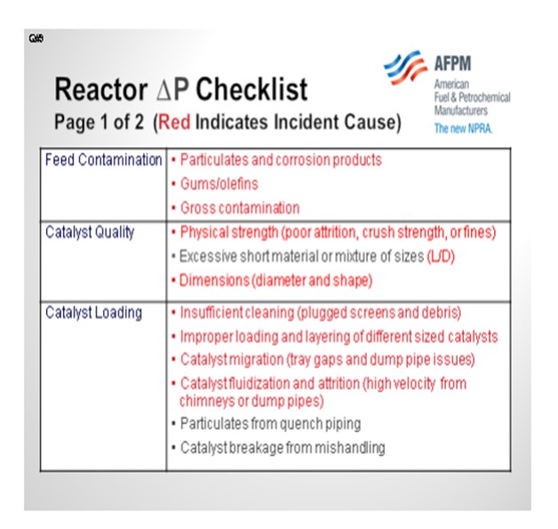
Fortunately, we have had good crime scene investigation capability that has allowed us to generate this checklist of possibilities. When performing any incident investigation, it is important to think about all of the possible causes. The following slide summarize our findings. The causes highlighted in red are ones that were actual root causes of an incident. Among them are classic feed contamination in the upper beds, catalyst quality issues with strength, and loading catalyst of the wrong dimensions. The process of catalyst loading is also critical. In the table below, we found four different root causes attributed to catalyst loading. Making sure that the catalyst loaders are properly trained and supervised is critical.
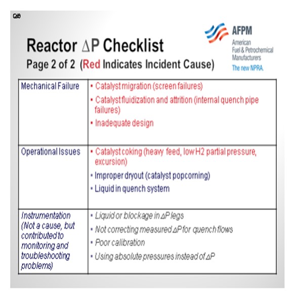
We have also seen mechanical failures in the reactors cause excessive pressure drop. In one case, a screen failure resulted in catalyst migration into the reactor internals. In another case, a quench pipe developed a leak, which then pulverized the surrounding catalyst to a powder.
Operational issues, such as loss of recycle, have been observed as a culprit of increased ΔP. We have also listed instrumentation as a category, even though it is not really a root cause, because it is critical to validate pressure drop issues and predict the point in time when the maximum allowable pressure drop will be reached.
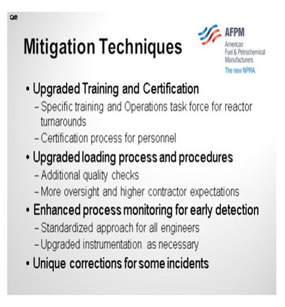
So, what did we do to mitigate this plague? We upgraded our training and certification program for operators. We now have an Operations Task Force for reactor turnarounds. This task force works with multiple hydroprocessing units across all refineries to help ensure successful turnarounds and prevent ΔP issues. There is a rigorous certification process the operators must complete to become part of the task force. Responsibilities include additional quality checks when loading, more oversight, and higher contractor expectations. We also have enhanced process monitoring for early detection, and we have standardized the approach of how all process engineers monitor for ΔP. In addition, we have upgraded instruments as necessary and made additional unique corrections.
BODOLUS (CVR Energy)
Steve gave a lot of examples. But historically, my key suspect for middle bed pressure drop is the precipitation phenomenon; that is, something dropping out as you go through the reaction profile. It brings to mind the old phrase a P-Chem (Physical Chemistry) professor used to tell us, “You know, if you are not part of the solution, you are part of the precipitant.” So as far as DP and middle beds, I always look for what might be dropping out of the solution, which could be the traditional carbon laydown if your gas-to-oil ratio is not good enough. Or in recent years, I have seen a lot of the asphaltene precipitant in middle beds that occurs as a result, again, of the destruction of the solvating compounds around the asphaltenes. They are often called maltenes.
Another key precipitation mechanism is the formation of the iron sulfides. As iron species come in with your feed, they may be part of corrosion products. They come in and may be in oxide form or part of water being brought in. But as you go through the water dew point, that iron has nowhere to go. And as you build up H2S down through the reactor profile, you have a tendency to want to form iron sulfides. Now once the iron sulfides form, they want to know where other iron sulfides are so they can hook up and precipitate; and before you know it, you have some crystals growing in the middle bed. These crystals will typically be iron sulfides.
Now I will address diagnosis, monitoring, and mitigation. Again, the mitigation is dependent upon the diagnosis of a true cause. Monitor each bed as a percentage of the overall reactor train DP. So if you are fortunate enough to have DP right across every bed, then each bed will have a percentage of the total ∆P, which normalizes out changes in gas-to-oil ratio and flow. Also, design the catalyst bed for a particular pour size, void volume, and inactivity profile, again, coming back to stacking the beds in your favor. There was an occasion where suspected precipitation in the reactor was not necessarily growing on the catalyst particles themselves like a carbon. In that case, we had good luck washing iron sulfides out with a low-temperature hydrocarbon flush. This flush can be done as a last-ditch resort when you find your DP building. The proof of that was in downstream coalescers and things like that that we would find. They became clogged when we did the flush with the oil, and analysis of that material showed it to be iron sulfides.
BODOLUS (CVR Energy)
High pressure drops in the second and/or subsequent beds of hydrotreaters may be an indication of incipient carbon laydown or other material precipitation. Excessive carbon laydown can result when hydrogen-to-oil ratios are outside required limits in successive beds. In some cases, contaminants can be introduced via quench streams adding to intra-bed pressure drop.
Precipitation of material other than carbon can occur depending on reactor conditions and feedstocks. Precipitants can include clays and minerals, most often from heavier Bitumen-derived feedstocks. For heavy feeds containing Asphaltenes, severe hydrotreating of the bulk liquid may cause precipitation of the Asphaltenes as solubility of these compounds are decreased with increasing conversion of the solvating compounds (maltenes). Other possible precipitants are fine iron sulfide particles that are produced as the degree of desulfurization produces higher hydrogen sulfide partial pressures down through the bed.
Monitoring pressure drop in all beds need to be looked at. A preferred technique is to set a base line that tracks the percentage of pressure drop through each bed versus total reactor pressure drop. This provides a simple way to “normalize” pressure drop for feed rate changes.
Mitigation efforts start with feed filtration to get as much solid material out of the feed as possible. Nominally, an efficient 25-micron filtration element is a good place to start while building a case for short-term filtration costs versus longer term bed pressure drop build. Careful selection of reactor bed grading and catalyst size can help extend cycle life. Increasing the particle size of the active catalyst bed can allow additional solids to pass through. Pay particular attention to the void volume of the previous loading and determine what future loading may be able to increase it.
On occasion, a low temperature (300°F) hydrocarbon wash can help reduce mid-bed pressure drop by changing the gas to oil ratio and bed hydraulics.
GREG ROSINSKI and CHARLES OLESEN (Advanced Refining Technologies)
There are several causes related to a poor turnaround or poor catalyst loading. A damaged or dirty outlet collector, dirty support screens or improper size grading at the bottom of a catalyst bed can all lead to high pressure drop in a lower bed. It is important that the reactor and screens be cleaned before loading any catalyst. Proper size grading of catalyst at the bottom of each bed is also important. If the catalyst size difference between grading layers is too large, smaller diameter catalyst can migrate through subsequent layers and ultimately plug the support screens or outlet collector. It is also critical to make sure nothing (tools, hardhats, etc.) gets left in the reactor during a loading.
Pressure drop in a lower bed can also be caused by the gradual accumulation of iron sulfide or other fines. These fines have small enough particles that they can be carried through upper beds. The particulates can then drop out in a lower bed. Some synthetic crudes may have fine particulates of clay or sand which can deposit in lower beds, as discussed in our answer to Question 5.
Excessive coke formation due to hydrogen starvation from poor gas distribution or low H2/Oil ratio combined with higher temperatures has also been identified as a cause of lower bed pressure drop. It is important to keep the H2/oil ratio above a specified minimum, and if reduced H2 availability is anticipated the charge rate should be reduce or cracked stocks removed for the period to ensure the minimum H2/oil ratio is maintained.
Another cause for lower bed pressure drops which we have seen involves debris or water introduced though the quench line. Quench systems should be drained and/or exercised while the catalyst is cold to prevent sudden water vaporization and breaking of catalyst pellets.
JAN KOURI (Petroval LP)
Although it is something done immediately after shutdown, getting a good composite sample of the catalyst bed may answer questions concerning pressure drop. There is a system called “PROBACAT” that is used to collect catalyst samples from within a catalyst bed. The system is capable of sampling 30’ (feet) to 40’ into catalyst beds and collect samples every 6” (inches) to 8” as it goes down.
Year
2012
Process