

Charles Toups
Ecorobotics


Question 28: What is the panel's experience in block mode operating between VGO and diesel modes? What is the frequency of change of mode and do they see any impact on catalyst activity after each switch?
OHMES (KBC Advanced Technologies, Inc.)
ESTEBAN (Suncor Energy, Inc.)
OHMES (KBC Advanced Technologies, Inc.)
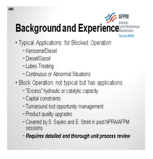
To clarify this question, the term “block mode” relates to the use of a single hydroprocessing unit to operate in at least two different operations, as defined by the feedstock and operating severity. Block mode operation has several applications in the refining industry:
• Kerosene and diesel,
• Diesel and gas oil, and
• Lubes treating.
In addition, this block mode operation can be applied on a continuous operating basis or used for abnormal situations, such as turnaround lost opportunity management or brief unit maintenance outage management.
Based on KBCs experience, using a single unit in multiple modes is not a typical application but does occur in the industry. The instances where block operation occurs are:
• Refineries with hydroprocessing unit(s) with “excess” hydraulic or catalyst activity capacity,
• Capital is highly constrained and maximization of existing assets are required,
• Managing abnormal situations, and
• Ability to upgrade product quality or move away from a product quality constraint.
These situations have been discussed in more detail by Scott Sayles and Eric Streit in previous NPRA/AFPM conference papers. Before attempting to utilize an existing unit in an alternate operation, a detailed and thorough unit process review and Management of Change are highly recommended and required.
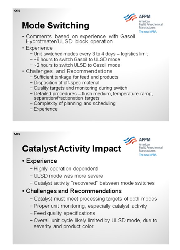
Mode Switching
In response to the question, the following information is based on KBC’s experience with refiners using a single unit to 1) produce ultra-low sulfur diesel and 2) hydrotreat gas oil for FCC processing. In this scenario, the unit ran in each mode for three to four days, and the length of time for each block was dictated by logistics (storing of unit feed and primary products). Therefore, the main constraint with a block mode operation is to have sufficient tankage to allow for storing material during the “down” mode.
The Best Practice mode switch times are about six hours when going from gas oil to ULSD mode and about two hours when going from ULSD to gas oil mode. Achieving these times requires very experienced Operations staff and detailed mode switch procedures. These procedures should cover such items as:
• Product quality targets and monitoring frequency during a mode switch, as well as certifying when the product is on specification, particularly when going to ULSD service,
• Reactor temperature ramping rates, as the two modes will normally have the reactor run at different WABTs, and
• Operating targets and ramping details for separator and fractionator operations.
• Unit flush procedures, including the order and rate that certain feed types are introduced (virgin versus cracked stocks)
For one particular client, virgin diesel was used as the primary flush material when moving from gas oil to ULSD mode. KBC worked with the client to introduce FCC LCO early in the flush period, thereby allowing the reactor to heat up quicker, due to the inherent exotherm, and improving removal of heavy gas oil components, which lead to improved switch times.
In addition to feed and product logistics, a significant challenge with block operation is the disposition of off-specification product. Therefore, including this material in the economics of the operation, as well as the planning and scheduling aspects, is critical to a successful and profitable operation.
Catalyst Activity Impact
As far as impact to catalyst activity, this impact is highly dependent on the operating modes selected, catalyst, feedstock, contaminants, and stable control. Based on KBC’s experience for well-run ULSD/gas oil operations, the catalyst activity normally recovers between the modes and mode switching, such that conventional catalyst deactivation is observed.
For successful catalyst activity management, several components must be in place. First, the catalyst, itself, should be capable of meeting the processing targets for both modes. The catalyst vendor can assist in that selection. Second, the Operations & Engineering staff needs to define and adhere to strict feed quality targets. Regular unit monitoring and catalyst activity tracking become more critical than a conventional operation.
One final point on catalyst activity involves the impact on overall cycle length. The typical scenario is that gas oil operations are limited at end-of-run (EOR) by reactor metallurgical design temperature or heat input, whereas ULSD operations are limited by product quality, such as color or cetane. When a block mode operation is utilized for both of these services, the ULSD mode will limit the unit cycle length, meaning that the catalyst still has activity for gas oil mode. Therefore, one has to either accept this giveaway of activity or consider alternative ways to produce ULSD during this extended period when ULSD mode is not possible, catalytically.
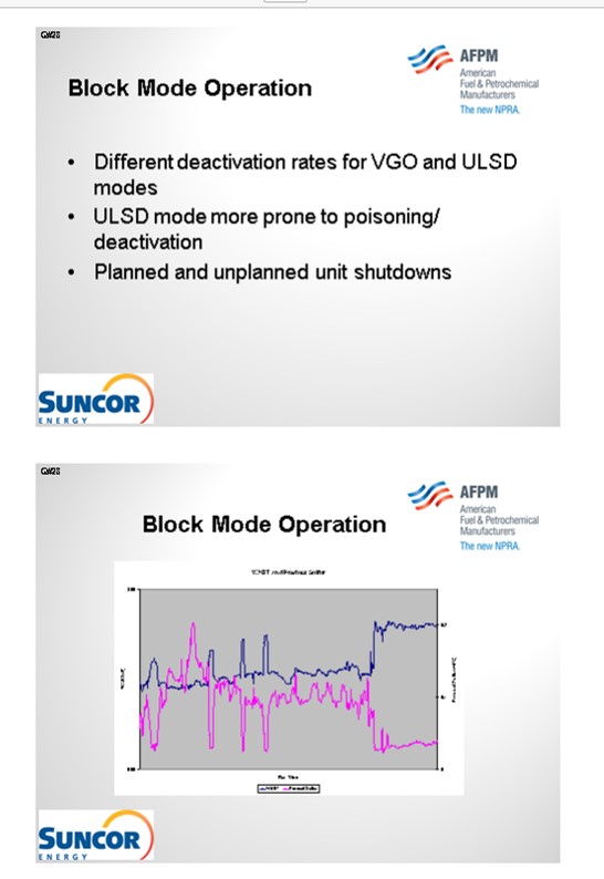
ESTEBAN (Suncor Energy, Inc.)
While Suncor Energy, Inc. does not have any hydroprocessing units designed to routinely operate in block mode between VGO and diesel, at our Denver Refinery we have operated our ULSD unit in AGO/VGO service and routinely operate our gas oil unit in ULSD service for various reasons. Our existing ULSD unit was revamped in 2006 from AGO/VGO service to ULSD service when Suncor constructed our new gas oil unit. Since the gas oil unit was not completed following a full plant turnaround the ULSD unit was initially started in AGO/VGO service and operated for three months prior to the swap to diesel service. Following the swap in service the unit performed well and easily met its designed life cycle. However, two distinct deactivation rates were noted during the course of the run. During operation in AGO/VGO service the deactivation rate was nearly double the deactivation rate in ULSD service, but these rates were predicted.
Similarly, also at our Denver Refinery, prior to the ULSD specification for non-road diesel Suncor often would feed a large volume of diesel along with AGO/VGO to the gas oil unit and increase severity to produce a side stream ULSD product from the unit, and the unit was revamped in 2011 to accommodate continuous operation in ULSD mode. Even though this mode of operation is not the same as block operation, the impact to catalyst deactivation rate of the varying modes of operation is predictable given known feed properties and target desulfurization.
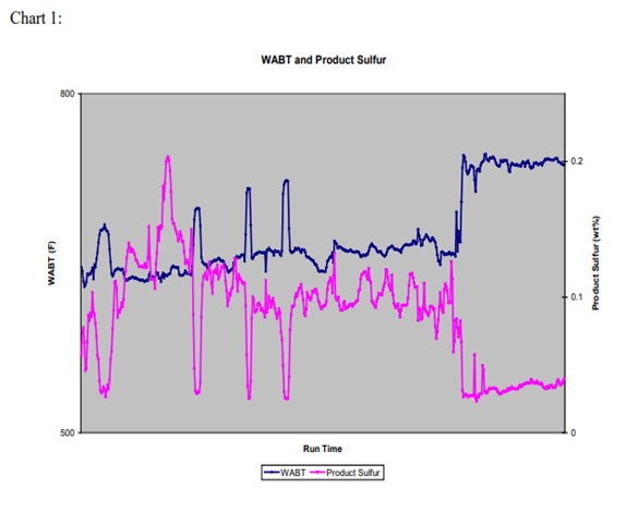
Some of the challenges to this operation are unknown feed properties or contaminates that accelerate deactivation or cause pressure drop build. As with any operation poisons and contaminates will result in the loss of activity, but this loss is much more noticeable when operating in ULSD service due to the difficult desulfurization required for ULSD production. In our experience with our gas oil unit, we have noticed step changes between periods of operation in ULSD service primarily due to feed contaminates in our AGO/VGO streams and purchased CGO streams that have both resulted in deactivation and pressure drop build, while our deactivation rate during periods of lower severity service is positive but steady. Operation of our gas oil unit in ULSD mode also has presented challenges meeting sulfur specifications as reactor weighted average bed temperatures (WABT) increase in the run due to the increase in cracking which results in more difficult sulfur molecules in the diesel boiling range. In order to counteract this we make efforts to balance our reactor temperatures with adjustments to our diesel cutpoint. The following chart depicts the impact on reactor WABT when adjusting product sulfur on the unit to operate in ULSD mode.
Based on our experience, we have ultimately found that the impact to catalyst activity in varying modes of operation regardless of frequency can be predictable given the proper information on feed stream properties and those impacts are amplified in ULSD production due to the level of desulfurization required.
ROBERTSON (AFPM) That concludes the Hydroprocessing session of this Q&A. I want to thank the panelists. They did a great job. And thank you all for coming.
Question 27: What are the Best Practices around minimizing risk of catalyst or equipment damage during turndown operation of a steam methane reformer hydrogen plant?
OHMES (KBC Advanced Technologies, Inc.)
OHMES (KBC Advanced Technologies, Inc.) and ROSS BRUNSON, III (Süd-Chemie, Inc.)
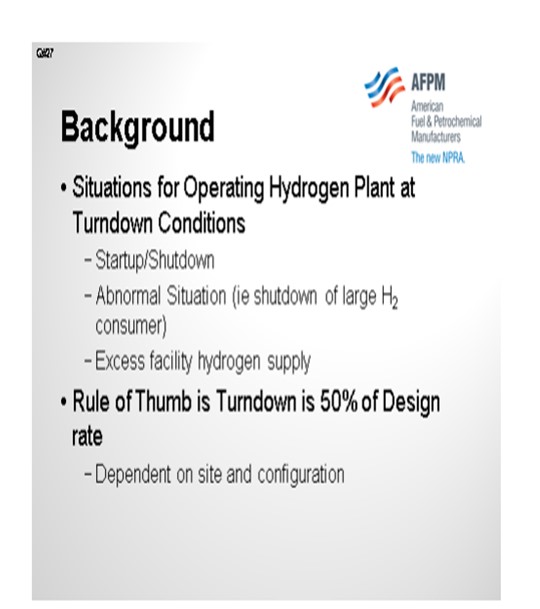
First, there are several scenarios where operating at a turndown condition is required:
• Start-up/shutdown
• Abnormal situations (i.e., when a large H2 consumer is off-line or shut down)
• Excess facility hydrogen supply (becoming more typical)
As with any non-standard operating scenario, the unit’s operation should be carefully reviewed, and clear operating procedures and guidelines developed.
The general rule-of-thumb is that most hydrogen plants are designed to operate continuously at 50% of original design capacity. A review of select hydrogen plant vendor’s experience on PSA plants resulted in the following (in no particular order):
• Foster Wheeler (FW) o Turndown to 50% is generally managed without significant changes in process conditions or equipment.
o Design changes and operator attention can achieve 30% turndown.
o The primary areas of focus are feed preheat, burner turndown, temperature distribution in the furnace radiant section, flow measurement, and PSA cycle time.
o With a FW Terrace Wall™ reformer, one level of burners can be turned off at low turndown to maintain burner control.
• CB&I
o The majority of plants designed to achieve 50% turndown.
o Plants can be designed for lower turndown ratio, typically to 30%.
o Primary focal areas are flow distribution and operating ranges of control valves.
o Increased steam/carbon ratios are recommended to maintain distribution.
o Parallel control valves can be utilized for stable operation at low turndown.
• Technip Stone & Webster
o They can typically achieve a 35% to 40% turndown.
o They have provided plants with a turndown capability of 20% to 25% of original design.
o Their primary focal areas are burner management, flame stability, and distribution.
A review of the original design criteria can clarify what the immediate minimum operation involves. As part of this review, or for those facilities that need to further reduce capacity, the following recommended practices should be considered:
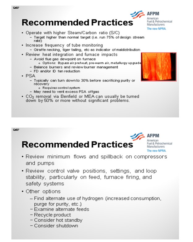
1. Operation with high steam/carbon (S/C) ratio: Depending on the feedstock and configuration, most units operate with an S/C ratio between 3 and 7. However, during a turndown situation, the operator should target a higher S/C ratio and run at least 75% of the design steam rate. Doing so helps maintain adequate mass flux in the tubes to achieve good distribution, avoid hot tubes, and minimize catalyst damage. Proper steam rate is the key issue when operating at turndown conditions. Maldistribution especially becomes a concern when the tube pressure drop reaches 10 psi.
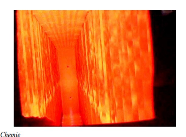
2. Increase frequency of tube monitoring: Normal practice is to complete visual and pyrometer temperature measurement of Reformer tubes once per shift. During turndown conditions, monitoring frequency should increase. In particular, look out of tubes that are operating hotter (i.e., whiter) than other tubes, hot spots (giraffe necking), or hot bands (tiger tailing).
3. Review heat integration and furnace impacts: Several aspects require review in the area of the furnace and heat recovery sections. First, avoid dew point of the flue gas, which leads to corrosion. In some cases, bypassing the air preheat, pre-warming makeup air, or metallurgy upgrades are required. Obviously, fewer burners are required in this scenario, so ensure the unit can maintain proper firing balance in the furnace at these conditions. Also, review the burner management protocol to avoid an unnecessary unit trip. Finally, there will be less load on the FD and/or ID fans, so review the capability to reduce fan operation while maintaining acceptable oxygen levels and draft.
4. Hydrogen purification implications: Whether the unit has a pressure swing absorption (PSA) system or a CO2 removal system (such as Benfield, Catacarb, or MEA), these sections of the plant can normally operate at lower turndown than the reformer section. PSAs can normally be run to 30% of design, but require a control system to do so, which most modern units already have included. The primary downside is a slight sacrifice in purity or hydrogen recovery. Depending on the fuel input requirements, some PSA off gas may need to be excessed from the unit.
5. Review instrumentation, pumps, and compressors: While normally not a key constraint at turndown conditions, the pump and compressor systems should be reviewed to ensure minimum flow operation is avoided. For most units, instrumentation often limits the minimum sustainable throughput. Therefore, review control valve positions, variable setpoints, control loop stability, and safety systems, particularly on feed rate, furnace firing, and steam injection control. In some cases, parallel control valve and alternate ranged flow indicators have been installed for units running regularly in turndown.
6. Consider other options: While operating at low rates may be required on a short-term basis, if this situation becomes the new “normal”, the following options should be considered to improve the utilization of the unit.
• Find alternate use of hydrogen, such as increasing hydrotreater purge rates to increase cycle length or raise unit severity to increase volume swell.
• Consider alternate feedstocks as the unit may now have capacity for opportunity feeds.
• Some operators have recycled product to maintain mass rates.
• Operate the unit on “hot standby” if the facility does not need the hydrogen but wants a backup source ready to put into service rapidly.
JOSH SIEGEL (Johnson Matthey)
There are several considerations around minimizing risks when operating a steam methane reformer hydrogen plant at turndown conditions. First it is important to control the heat input to the furnace. It may be necessary to throttle back and/or turn off burners in the furnace to maintain the desired exit temperature. If the exit process gas temperature indicator is located in the exit header, it may not give an accurate reading of the gas temperature at the catalyst exit due to the increased heat loss, and as such we recommend operating to a fixed methane slip. To avoid overheating the catalyst it is important that frequent monitoring of the reformer tubes be completed. It is recommended that tube wall temperature (TWT) measurements be completed at least once per day, along with several visual inspections of the tubes, to locate any indications that there is overheating.
Secondly, the maximum turndown rate is a function of the plant’s design and will vary from plant to plant and site to site. Manufacturers of steam methane reformers have a minimum recommended flow rate to achieve good flow distribution through the tubes. Inaccurate flow meter readings could lead to maldistribution of flow through the primary reformer resulting in localized heating. This localized heating can cause catalyst deactivation from both sintering and carbon formation, and a reduction in steam methane reformer tube life which could subsequently result in tube failures. To address this, key instruments, such as feed and steam flows, should be pressure and temperature compensated. If the steam to carbon ratio is increased during turndown to maintain mass flow through the primary reformer, it is important that the resulting operating conditions do not lead to oxidation of the steam reforming catalyst. If the plant has a low temperature shift reactor (LTS), the LTS inlet temperature needs to be maintained at least 30°F (15°C) above the dew point of the process gas as the steam flow rate is increased.
Heat integration is another aspect to consider when running a hydrogen plant at turndown rates. It is important that the inlet temperature to the purification system stay above 570°F (300°C) to maintain the most efficient removal of poisons such as sulfur and chloride. If the temperature to the purification system falls below this level the efficiency of the removal process for these poisons will decrease which could result in slippage and the poisoning of downstream catalyst.
Year
2012
Process
Question 26: What catalyst and metallurgy design considerations are important when evaluating the co-processing of highly acidic renewable distillates? What can be done to mitigate carbon monoxide formation?
STEFANO MELIS (Albemarle Corporation)
Acidity of renewable distillates can be intrinsic of the material (free acids of the vegetable oil) or generated during its conversion in the hydrotreating unit. Typically, free acids in vegetable oil amount to about 5%. This means that crude vegetable oil has a TAN number around 7, which requires special metallurgy for the pipelines to the feed drum. Once the vegetable oil (VO) is mixed with oil, acidity is reduced by dilution. For a typical co-processing operation, where VO intake ranges around 5% to 10%, standard metallurgy is, therefore, suitable for the connection between feed drum and reactor. At increasing intakes (i.e., above 10%), special metallurgy would be required.
An alternative is to directly resort to refined vegetable oil. In this case, VO is acid-free; therefore, no corrosion issues are expected in any part of the feed section. This solution also prevents fouling problems associated to VO impurities, such as sterols and phospholipids.
Acids are also formed during the conversion of VO to hydrocarbons. Indeed, triglycerides decompose to carboxylic acids (which then further react to yield paraffins). Since the triglycerides decomposition proceeds gradually along the reactor and the produced acids are readily converted, no local spots with acidic material are expected. Standard metallurgy of hydrotreating units is, therefore, suitable for these operations, except for those units with very poor metallurgy (often with very low design pressure).
As mentioned above, decomposition of triglycerides leads to carboxylic acid formation which, in turn, yields paraffins. This latter step can occur through different mechanisms: hydrodeoxygenation (HDO, yielding paraffins and water), decarboxylation (DCX, yielding paraffins and CO2) and decarbonylation (DCN, yielding paraffins, CO and water). The latter two mechanisms are linked by the Water Gas Shift reaction. The straightforward way to decrease CO is to force the reaction to proceed through HDO, favored by high pressure and low temperature. Catalyst selection is important since the system requires high activity both for HDS (in order to reduce the operating temperature to reach the S target) and for hydrogenation (to enhance HDO). Another possibility is to catalyze the hydrogenation of CO to methane. This reaction, however, being highly exothermic, can cause local high ΔT, resulting in possible formation of hot spots. Additionally, the methanation reaction has high hydrogen consumption and, as such, is an inefficient way to use hydrogen. This should also be taken into account is considering downstream methanation, for example, in the high-pressure separator.
In general, CO generation from bio-feed co-processing can be managed. Driving the reaction of renewable material through DCN leads to a significant reduction in H2 consumption compared to alternatives. Produced CO accumulates in the recycle gas and leads to strong inhibition of HDS reactions, but this effect can be kept under control with proper catalyst selection. Depending on the configuration of the refinery hydrogen network, CO containing gas can be either purified (for example, by PSA) or directed to other units where its inhibition effect is less severe.
Overall, operating strategy and catalyst selection for the co-processing of renewable material should be analyzed in great detail to find the optimal reaction path that provides the best compromise between H2 consumption, detrimental effects of CO and product yield structure.
Year
2012
Process
Question 24: Given the potential consequences of back flow in high pressure hydroprocessing services, such as furnace tube rupture and pump shutdown, what layers of protection are being employed to reduce risk?
ESTEBAN (Suncor Energy, Inc.)
We are going to skip the first slide.

The second slide shows a simple depiction of the layers of protection that we use at our different sites. In some cases, we have relief protection, basic process controls, and critical alarm systems on our feed drums to prevent a backflow scenario or the consequences of a backflow scenario. That being said, though, relief valves do not always provide an adequate level of protection for high pressure units. So obviously, take that with a grain of salt. Our primary layer of protection is provided by our trip valves which are activated by SIL-rated instruments. We do not have an SIL rating in all cases; but in some cases, it is required to get the level of protection we need. And then, of course, we also employ dual check valves of differing types downstream of our pumps. Those check valves will typically wind up on our critical check valve system as well.

The scenario is similar where you have backflow. It is not so much the concern of backflow of reactor contents through the furnace, but more just a loss of containment in the furnace itself. We do not treat these furnaces in our hydroprocessing units any differently than we do any of our other furnaces in the refinery. They all have an integrity operating window that we would like to stay in. That window defines at what burner pressures we need to operate and, of course, at what skin and overall box temperatures we can operate.

Our layers of protection are very similar here in that we have trip valves activated by SIL-rated instruments and which are only SIL-rated as required. And of course, we have basic process controls and critical alarm systems. In some, but not all, cases, we do have check valves downstream of our furnaces. That is not a standard at all our sites. However, on some sites, we are consistent about having check valves downstream of our furnaces.

KEVIN PROOPS (Solomon Associates)
I would like to comment on the heater part of the question. Reactor charge furnaces potentially have substantially higher consequences of failure than do most of the other furnaces in your refinery, so you need to be a lot more scared of them than you do of the other ones.
First, this is generally an exothermic process; so, the best case is probably that the furnace is not firing or is only minimally firing. Adequate feed-effluent heat exchange reduces firing and thus the risk of failure from flame impingement. Second is the inherent safety design. If you can go to a single-phase furnace instead of a two-phase furnace, then if it does rupture, your consequence will probably be a lot less. That also gets into the control system issues. Some refiners use hot oil utility instead of a fired heater in the hydrotreater. This is inherently safer.
Then you get into how to avoid a tube failure in the first place. There are a lot of ways to do that, but consider dry point in naphtha units, burner ring pressure controls and interlocks, and maintaining the cleanliness of the burners (fuel gas filtering). Adequate burner-to-tube spacing, feed filtration, tube monitoring (thermography), operator rounds frequency, and upgraded tube metallurgy can all add layers of protection.
Finally, it comes down to culture as well. You do not want to get into a situation of risk of a failure competing with profit to keep the unit maximizing at full throughput. Unfortunately, I have seen a case where that did happen: A furnace was experiencing flame impingement, and the operators did not reduce charge to the unit. After one shift, a tube failed, which led to the entire unit being consumed in a flash fire within a few seconds. We were very fortunate that there was no one outside at the time it happened; if there had been, we would have killed anyone in the unit.
ESTEBAN (Suncor Energy, Inc.)
We do treat them differently depending on their operating pressures and/or requirements. Certainly, from a design standpoint, the operating envelope for each individual piece of equipment changes how the furnace is designed overall. That being said, we evaluate all equipment using the same standard with a process hazard analysis to determine the appropriate layers of protection. Given the required layers of protection, we identify additional safeguards as required by LOPA. SIL-rated instruments, for example, are not required for all burner management systems. However, in some cases, they may be required because the consequences of failure are higher.
So yes, the consequences are significantly greater on a high-pressure furnace. The assessed risk ranking would define how those layers of protection will appear. In some cases, you will see a simpler system on a furnace; and in others, much more complex layers of protection will be applied because of the potential consequences of equipment failure for that furnace. So, to re-phrase my response, I will say that we evaluate every piece of equipment using the same processes.
ESTEBAN (Suncor Energy, Inc.)
In order to reduce the risk of potentially catastrophic consequences related to backflow in high pressure hydroprocessing services Suncor Energy, Inc. uses several independent layers of protection at operating pressure boundaries. One common boundary is for hydroprocessing units, is between the unit feed drum and the reactor charge pump. A typical hydroprocessing unit will have relatively low design pressure equipment upstream of the reactor charge pump which boosts the operating pressure of the feed stream to the much higher reactor operating pressure. As such preventing back flow in the event of the loss of a feed charge pump is critical to prevent equipment failure in upstream equipment with catastrophic consequences. In this application Suncor Energy, Inc. applies the use the following layers of protection:
1. Primary protection is typically a Safety Instrumented System (SIS) that monitors the run status of the feed charge pump via multiple direct and indirect instrumented signals and activates quick acting trip valves and in some cases closes the feed charge control valves in the event of a shutdown. In some cases, depending on the unit specific hazard analysis these systems may be SIL-rated to ensure reliable operation when activated. In addition, these systems are often designed to be activated by any one of several different instruments used to sense a potential backflow scenario, i.e., low-low flow shutdowns and low-low feed controller differential pressure shutdowns.
2. In some cases, pressure relief valves are used as layers of protection for overpressure due to backflow, but caution must be applied when relying on a relief valve as protection for vessels, such as feed drums, since these valves are not always sized for backflow scenarios.
3. Mechanical safety systems are also employed depending on unit design. While these systems are often not credited in a process hazard analysis of a unit they can provide additional layers of protection. Typical installations include dual check valves of different design which are often deemed critical check valves that require routine maintenance.
4. Provided the design of the system and equipment in some cases basic process controls and/or critical alarms with operator response are employed as additional layers of protection.

In addition to backflow prevention and protection as it relates to pressure boundaries, furnace tube ruptures can result in backflow from multiple large high-pressure vessels to atmosphere with catastrophic consequences. In order to address the release of reactor and high-pressure circuit equipment, layers of protection must be applied to the feed furnaces that prevent operating windows that have the potential to create damage resulting in tube rupture. The layers of protection employed for this scenario do not differ from those on other furnaces in Suncor’s refineries, as all furnaces are evaluated for tube rupture scenarios. However, in this application Suncor Energy, Inc. applies the use of the following layers of protection:
1. Primary protection is typically a SIS that monitors furnace flows, temperatures, and fuel and box pressures via multiple direct and indirect instrumented signals and activates quick acting trip valves on fuel supply and in some cases closes the fuel supply control valves in the event of operation outside a preset operating window. These SISs often activate related SISs to stop process flows. In some cases, depending on the unit specific hazard analysis these systems may be SIL-rated to ensure reliable operation when activated. In addition, these systems are often designed to be activated by any one of several different instruments used to sense operation outside of the specified window, i.e., low-low flow shutdowns and high-high burner pressure shutdowns.
2. Mechanical safety systems are also employed depending on unit design. While these systems are often not credited in a process hazard analysis of a unit, they can provide additional layers of protection. Typical installations include check valves downstream of furnaces to prevent the backflow of reactor contents. In general, these check valves are not relied upon as fail-safe devices and are not considered critical check valves.
3. Provided the design of the system and equipment in some cases basic process controls and/or critical alarms with operator response are employed as additional layers of protection.

Year
2012
Process