Question 15: What can be done to mitigate foaming and emulsion formation in our hydrotreater high pressure separator? Is there any favorable experience with injection of antifoam/chemical emulsion breaker?
ROBERTSON (AFPM)
Since we only have about 40 minutes left to get through 12 questions, we are going to just take primary answers now. The secondary and third answers are in the Answer Book.
OHMES (KBC Advanced Technologies, Inc.)
We are starting to hear about more foaming problems, particularly with some of the unconventional or shale crudes being processed, and there are a few other instances. First of all, I will admit that a lot of these were covered in the early 1990s in the NPRA Q&A, and I shamelessly borrowed from them, noting that I had done so. Also, there was a really excellent article by Turner et al from Marathon that discussed the problems they had and how they went about to solving them. Obviously, we have run into a few of these issues as we have talked with clients.
So just briefly, refiners are typically finding some amount of foaming occurring. One will normally see either some liquid carryover, problems with level control where you are not truly seeing the level itself, and/or a lot of hydrogen under carry. I will skip most of these slides since I already touched on them.
Ultimately, the problem is really around separation. Maybe you have expanded the unit and did not take a look at the separator, thinking it would be okay when, in actuality, it did not have the capability for good separation. There are a few other problems people have seen, particularly if they have a recycle hydrocracker with a lot of HPNA, such that foaming will occur. As an example, Marathon has units processing feeds with high asphaltenes, particularly those with DAO (deasphalted oil). Another minor problem we have heard is that several people changed the process chemistry of their washwater and were getting some chemicals that were causing some foaming. Exchanger leaks can cause this, obviously, if you are running higher temperatures.
What are some options that you can use to fix this problem? First of all, we would start looking at your plant data. If you see a lot of hydrogen under carry showing up downstream in your separators, fractionator, or stripper, you can compare that quantity to what the thermodynamics will tell you to determine if there is an opportunity to not only stop the foaming, but maybe also recover some hydrogen. You could do some sampling to check the leaks. But honestly, what most people have had to do to isolate the problem is just do some test runs, pull out feed to check for a hydraulic issue, and play with some of the individual feeds, whether they are DAO or not.
So a few of the mitigation options: There are chemicals available, and we have seen people use them. To be honest, it is a bit hit-and-miss. For the ones who have been successful in using chemicals, their use is normally a short-term gap to get them through to a shutdown in order to fix the separator. From most of what we have seen, people have either had to replace or revamp the separator.
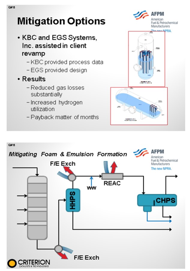
One example occurred when we worked with a company by the name of EGS. They design and manufacture Vortex Tube Clusters, which are a variant of a hydroclone. Although it is a little hard to see on the diagram, these tubes basically sit down within the liquid, which forces the vapors to go through the tubes. By going up and through the tubes, the emulsion is broken, thereby giving you the benefit of not only minimizing the foaming but also reducing the hydrogen undercarry. So with this particular client, we provided some of the process data because we were doing unit operability improvement work; EGS developed the revamped design. The client saw such a significant reduction in the gas losses that they were able to increase severity and throughput, thereby reliving the hydrogen constraint. So to summarize: Look at your plant data, and do some test runs. But for all intents and purposes, you are probably going to have to do some type of a modification to your separation equipment.
CARLSON (Criterion Catalysts & Technologies)
This phenomenon has tended to be observed with hydrotreater multistage recovery section designs when a change in the hot high-pressure separator (HHPS) operating condition led to a foaming/level control problems in the cold high-pressure separator (CHPS). When observed, the foaming in the CHPS appears to be very sensitive to the temperature at which the HHPS is operated at with foaming indicated above a particular range. This is most likely due to a change in the vapor liquid equilibrium or possible entrainment resulting in heavier than expected material being routed to the CHPS resulting in a tighter HC/H2O emulsion forming after injection of the washwater. The higher HHPS operating temperatures leading to this problem may have been due to operating the reactors at a higher EOR temperature or from fouling in the F/E (feed/effluent) exchangers. This issue can often be mitigated by the cleaning of F/E exchanger and somewhat managed by a modified descending quenching strategy of the catalyst beds.
OHMES (KBC Advanced Technologies, Inc.) and DAVID LEAKE (EGS Systems, Inc.)
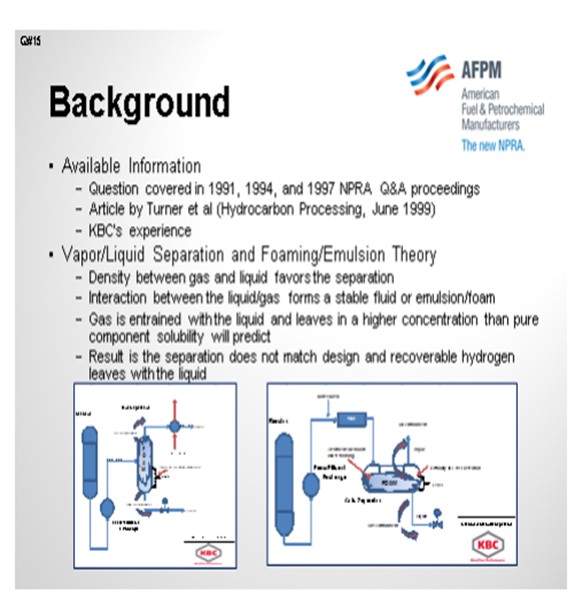
These particular questions were addressed in the early to mid-1990s NPRA Q&A sessions, specifically 1991, 1994, and 1997. In addition, an article was published in 1999 by Turner, et al that addressed the issue of foaming and emulsions (Hydrocarbon Processing, June 1999). The following response includes the information from those sources, as well as KBC’s experience in dealing with foaming and emulsion problems in hydroprocessing units.
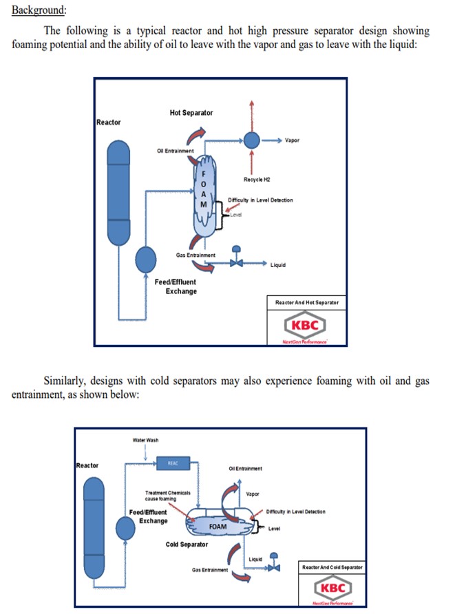
Separator designs assume gravity separation and residence time will be sufficient to separate gas and liquid. The following is a brief description of the design process:
• Density between gas and liquid favors the separation.
• Interaction between the liquid and gas forms a stable fluid or emulsion/foam.
• Gas is entrained with the liquid and leaves in a higher concentration than pure component solubility will predict.
• The result is the separation that does not match design and recoverable hydrogen leaves with the liquid.
Causes and Indicators of Foaming and Emulsions:
Based on these information sources and KBC’s own experience in this area, the following are the causes of foaming and/or emulsions in high pressure separators:
• Hot Separators
o Inadequate separation capability increases with throughput or recycle gas rate,
o High content of polynuclear aromatics (PNAs) in hydrocracking seems to form stable emulsions, and
o High asphaltenes in feed, particularly when processing deasphalted oil (DAO) or resid.
• Cold Separators
o Chemicals in injected washwater,
o Exchanger leaks, and
o High temperatures in separator.
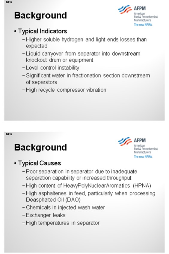
The typical indicators that a unit is experiencing foaming or emulsion problems are:
• Hot Separators
o Higher than expected hydrogen and light ends losses,
o Liquid carryover from separator into downstream exchangers resulting in loss of heat transfer, and
o Level control instability.
• Cold Separators
o Level control instability,
o Significant water in fractionation section downstream of separators, and
o High recycle compressor vibration.
Mitigation Options:
Prior to selecting a mitigation method, the refiner determines the root cause of the problem or at least narrows down the list of potential causes. The first indication is that the fractionator or stripper off gas hydrogen content is much higher than design. This situation also can cause the fuel gas amine absorber to become over-loaded. Recycle gas flow is less than design and heat is lost in the feed/gas exchangers leading to over-firing of the charge heaters.
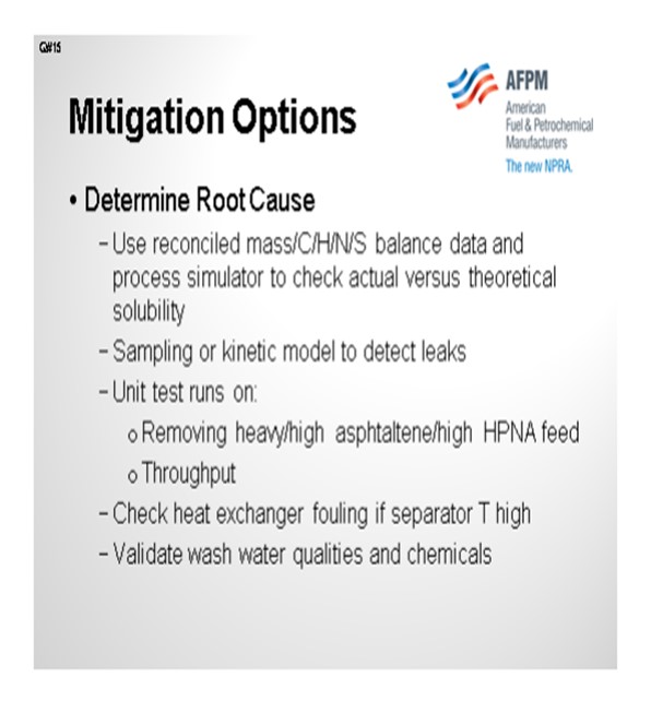
To determine if hydrogen and light ends soluble losses are high, the reconciled mass balance and elemental balances (carbon/hydrogen/sulfur/nitrogen) are compared to a simulation of the unit’s light ends and hydrogen loss. If the actual losses are significantly higher than the value based on thermodynamics, then the separator likely has a problem, and the potential improvement value can be calculated. This same approach, when accompanied by a kinetic model and some select sampling of additional unit streams, can help validate if exchanger leaks are occurring.
For validating potential causes such as operating conditions or feedstock type, a series of short-term test runs can be completed. If the unit is processing a new high asphaltene content feed, then removing the feedstock may reduce the foaming. Of course, replacing the feedstock to maintain relatively constant unit throughput will allow verification of feedstock type versus throughput as a cause. Upstream fouling of exchangers may be leading to elevated separator temperature, such that the remedy is exchanger cleaning rather than a unit modification. Finally, washwater quality and source should be validated to ensure that unknown chemicals are not being injected into the water and driving the foaming or emulsions.
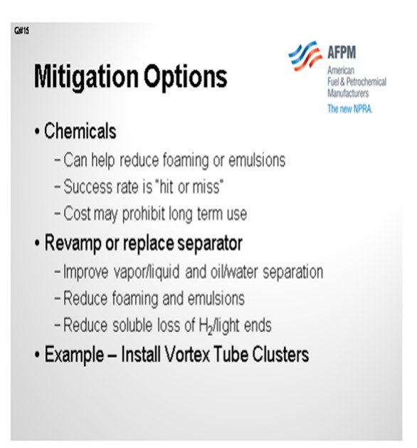
Chemical addition to improve foaming or break emulsions are an option. However, based on the past NPRA responses and KBC’s experience, the success rate is “hit or miss”. Those units that have had success are able to properly disperse the chemicals in the separator to achieve the desired improvement, so some type of an injection system will be needed. A short test run with chemical injection may give a preliminary indication of improvement. Most users have avoided chemicals as a long-term solution due to the typical costs.
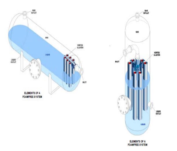
The most successful mitigation of foaming and emulsions is to improve the separator through revamp or replacement. KBC has direct experience with such a modification. For a client who was experiencing significant separation problems in a resid hydroprocessing unit, KBC partnered with EGS Systems, Inc. to revamp a high pressure separator, with KBC providing the necessary process data and EGS providing the design. The primary revamp involved installation of vortex tube clusters (inlet defoamer) internals. The advantage of these designs is no change is made to the high pressure containment vessel. The cyclones are internally supported, and no attachment welds are required.
The following schematics, courtesy of EGS Systems, Inc., provide generic examples of these vortex tube clusters installed in a horizontal and vertical separator.
For this particular installation, the revamp greatly improved separation, such that the entrained gas losses decreased dramatically and unit hydrogen utilization increased. Therefore, the economics payback was a matter of months, not including the impact of foaming and emulsion reduction. KBC’s experience is foaming and emulsion problems require some modification or upgrade to the high pressure separators to improve oil/water and vapor/liquid separation. As a final note, foaming in the amine contactor within the high pressure loop was excluded from this response, as this topic has been covered extensively in past NPRA proceedings.