Concurrent Session: Lessons Learned from Beaumont
Hear the inside story of the United Steel Workers lockout in Beaumont, TX that lasted 10 months.
MALLER (TechnipFMC Process Technology)
Standpipe stability is highly dependent on the design. Some units do not have any aeration; some units have aeration that they never look at over the run; and some units require constant monitoring on a weekly or even daily basis. So, it really depends upon the design. What we are looking at is the number of head built inside the standpipe and the density through the various sections in the standpipe. It is important to have an understanding of the baseline condition and targets before you run outside and start trying to adjust the aeration.
So, what would prompt a change? If you are going to turn down, you will be looking at lower circulation rates. There is a regime where the standpipe is not going to perform well, wherein the flux rates are about 60 to 100 pounds per second per foot squared. That is the regime where the bubbles are no longer flowing downward. They start wanting to flow upward and coalesce into bubbles that are large enough to start affecting the catalyst flow.
What I like to do is monitor the pressure profile all the way down to the standpipe, with a single-gauge survey on various intervals, to get a good understanding of how it should be performing. You should be able to use the aeration taps to measure the process pressure inside the standpipe. You can take a pressure reading on each one of the taps and make a map plotting the height elevation of that tap versus the measured pressure.
What a well performing standpipe will show is more or less a linear increase in pressure as you go down on the same pipe. Seeing areas where you are not getting the pressure being built up as much as it is in other areas could be an indication that you will want to adjust the aeration in that area. Also, seeing areas where you have pressure drop in the standpipe can be an indication that you are putting in too much aeration. Some FCC units that have really finicky standpipes have installed purged taps with pressure transmitters down the standpipe in order to monitor this profile online. That may be a good option if standpipe stability is a major concern. That way, everything is recorded so you can go back into the historian to see trends so you will be prepared for future standpipe performance.
If that is not possible, you can always look at the instruments you do have available. A standpipe will typically have some kind of level instrument on the upstream side of it. There should be purged tap there. You can either use an online calculation in the DCS (distributed control system) to get a pressure reading at that location, or you could put in a dedicated pressure transmitter instrument which would piggyback on that existing tap. Then, do the same on the upstream side of the slide valve to get the pressure reading directly above the slide valve. You would then have an online measurement of what the head is being built in that standpipe, independent of what is happening on the downstream side of the slide valve.
TRAGESSER (KBR)
Alex did a good job of answering the question. I will just add a more high-level comment. The overall goals of a FCC standpipe are to transfer catalyst from one vessel to the other and to help ensure that the slide valves or plug valves are operating within a reasonable range and have a steady dP to ensure a steady flow of catalyst. Since we are in Austin, I think a quote from Darrel Royal may apply here. He used use to say, “When you throw a pass, three things can happen and two of them are bad.” I think the same applies to adjusting standpipe aeration: The potential outcomes could be that 1) nothing will change; 2) it may get worse; and 3), you could get lucky and it might actually improve. So, if you have good steady slide valve dPs, it is not recommended to try and make it better.
I would like to mention one thing related to the standpipe: In order to have a standpipe with a good pressure buildup, it is important for the catalyst to be properly fluidized before entering the standpipe. If it is not well fluidized when it leaves the cone, there is not much that can be done to correct this problem in the standpipe and it will be a frustrating exercise to try. Depending on the design, there may be fluidization in the cone that will need to be set properly for this to occur.
FEDERSPIEL (W.R. Grace & Co.)
I agree with what has been said. I just want to touch on the catalyst contribution to standpipe aeration. Not only do changes in operating conditions, feed rates, and fluxes prompt an evaluation, changing the catalyst type should probably also prompt that same evaluation. The graph on the slide is demonstrating this maximum stable expansion ratio: a ratio of the density for incipient fluidization over the density for incipient bubbling. It really gives you a window of a healthy operation. As we go through standpipes, we are compressing the catalyst flow and changing the circulating density. What we see here is not just the average bulk density; it is actually a proxy for particle density. It plays a role in that maximum stable expansion ratio, but the fines content does as well. So, anytime you run into an issue where you might be losing fines material, it is likely that you will probably need to go out and adjust the standpipe aeration because it might be moving the window of your healthy operation.
J.W. “BILL” WILSON (FCC Consultant)
All of these comments are good. I want to add one more that was prompted by the statement said about optimization. I think the best rule for dealing with standpipes is: If it is not broken, do not fix it. As Steve said, there are three things that can happen, and two of them are bad. More often than not, the two that are bad will happen when you are playing around with the standpipes. By being ‘not broken’, I mean that you are getting adequate pressure buildup in the standpipes. So, if you have good pressure drop across the slide valves and that pressure drop is stable, do not fix it. So, if you are not getting the most delta, the most apparent density, or the most pressure buildup you can out of the standpipe, who really cares if you are getting enough? You can spend a lot of time going from a 35- to a 40-lb/ft3 (pound per cubic foot) apparent density in that standpipe and gain absolutely nothing, in terms of unit operation, and greatly increase the chances that somewhere in the process you will shut down the unit.
ZIAD JAWAD (Phillips 66)
I think one of the biggest problems with troubleshooting standpipes is the fact that the taps are not accessible. So, it is important that during the turnaround, when you have access to those taps, make sure that the root valves are working and not plugged. When you go through your inspection, stick a wire rod through just to make sure you actually have a tap you can work with during the run if there is a problem.
ALEX MALLER (TechnipFMC Process Technology)
Standpipe aeration is something which has been studied and reported on since the inception of cat cracking. Some standpipes require no attention and may not even have any aeration provisions provided. Others may be so sensitive to changing conditions that adjusting aeration is a daily action. Standpipe design is the most important factor. They tend to be very sensitive to changing direction, such as going from vertical to slanted.
The operational changes that would prompt a review of the standpipe performance are changes in catalyst circulation rate. Standpipes tend to not perform well in a certain range of catalyst flux, where the bubbles formed by the aeration flow neither down nor up. Instead, they coalesce together until they are large enough to have buoyancy to flow in the upward direction. These large bubbles can block the catalyst flow and are a source of instability in the slide valve dP. The range of catalyst flux which is to be avoided is generally 60 to 100 lb/ft2/sec (pounds per square foot per second).
An important aspect to monitor when reviewing standpipe operation is the pressure profile in the standpipe. Some units have dedicated, purged, pressure instruments along the standpipe for this purpose. Another option is to consider a pressure instrument on the aeration tap to give an indication of the pressure inside the standpipe. Most units just use the slide valve dP to indicate standpipe performance as the downstream pressure is usually constant; therefore, any variance in dP is changes in the head being built in the upstream standpipe. One suggestion is to consider a pressure instrument that piggybacks off the upstream slide valve dP tap. This pressure transmitter would give a direct reading of the pressure at the base of the standpipe. Having the same type of pressure tap upstream of the standpipe, such as on the high pressure tap of a level instrument, will give a direct reading of the standpipe head being built.
Regardless of your instrumentation arrangements, it is important to take regular single-gauge pressure surveys to understand the baselines for standpipe performance. These surveys should be taken at multiple elevations down the standpipe. If taking a reading off of an aeration tap, ensure that the aeration air is temporarily throttled to ensure that the backpressure through the tap is not impacting the pressure reading. An area in the standpipe where no head is being built is an indication that aeration adjustment may be warranted.
Although it is important to ensure standpipe fluidization over all modes of operation, when standpipes are not stable, operators have a tendency to want to increase the aeration rates to the taps. Overaeration of a standpipe can show similar symptoms as an underaerated standpipe. Both should be avoided. Establishing a good baseline of proper standpipe performance will help to give you a better idea of which direction to turn the valve when adjusting aeration of a finicky standpipe.
MICHAEL FEDERSPIEL (W.R. Grace & Co.)
Standpipe aeration is provided to replace the volume of gas lost in a fluidized catalyst as head pressure builds and compresses the gas. Not all standpipes have provisions for aeration; usually those without aeration taps are short in length and have minimal change in direction. Longer standpipes require aeration to ensure the smooth circulation of catalyst and sufficient slide valve delta P.
To calculate how much aeration a given standpipe requires, the first step is to calculate the volume of circulating catalyst emulsion (VEmulsion).
VEmulsion = QCatalyst/ρEmulsion
VEmulsion is used to calculate the volume of gas circulated with the catalyst.
VGas = VEmulsion * (1 – ρEmulsion/Skeletal Density)
The next step is to calculate the absolute pressure at the inlet to the standpipe and at each aeration tap location.
PInlet = PDilute + ρEmulsion * ΔH where ΔH is the distance from the inlet to the top of the bed
and
PTap = PInlet + ρEmulsion * ΔH where ΔH is the distance from the tap to the inlet
Finally, the calculated terms VGas, PInlet, and PTap are used to compute the change in gas volume due to the increased pressure.
ΔVGas = VGas – (VGas * PInlet)/PTap
ΔVGas is the theoretical amount of aeration required at each tap. Note: Each tap must be calculated individually, and experience shows the actual aeration requirement is usually 30% lower than theoretical.
Large changes in catalyst circulation rate, bed density (emulsion density or ρ in the calculation above), or system pressure should trigger an optimization of standpipe aeration. Additionally, if any taps along the standpipe were to become plugged with catalyst, the surrounding taps would need an adjustment.
Although the skeletal density of different FCC catalysts is usually very similar, changes in catalyst can impact the emulsion density and pressure profile and require aeration optimization. Catalyst properties (along with aeration medium) also sets the maximum stable expansion ratio (MSER), which is defined as:
MSER = Catalyst Density at Incipient Fluidization/Catalyst Density at Incipient Bubbling
The MSER indicates the “width of the operating window” over which a bed of fluidized catalyst is well-behaved. In the context of a standpipe, the MSER indicates how much a fluidized bed can be compressed before it will revert to a packed bed (defluidizes). The MSER is a function of catalyst particle density (with ABD used as a proxy) and 0-40 fines content, as shown in Figure 1.
Figure 1. Maximum Stable Expansion Ratio at Different Catalyst Properties
Monitoring the physical properties of the FCC catalyst is an important part of standpipe aeration optimization. Changing catalyst types should cue an evaluation of the standpipe aeration. Taking a single-gauge pressure survey of the standpipe can give valuable insight into the condition of the standpipe’s aeration. This survey is especially important to do while the unit circulation is healthy in order to establish a baseline, as shown in Figure 2.
Figure 2. Typical Standpipe Pressure Profile
Pressure profiles, like those in Figure 3, indicate it is time to adjust standpipe aeration.
Figure 3. Abnormal Standpipe Pressure Profiles
Finally, monitoring slide valve delta P is another method of tracking standpipe aeration. If the slide valve delta P unexpectedly changes or becomes erratic, the standpipe aeration should be reviewed.
FOOTE (CHS Inc.)
Unreliable ESP dumping can lead to shorting out of the transformer rectifiers and the associated missions troubled by losing a cell of your ESP. Also, inconsistent dumping can put operators directly in harm’s way just since they are not consistent in the way they dump; and then indirectly, if the dumping leads to unit shutdown which will expose them during the shutdown. So, reliable operation of those hoppers is important.
At CHS, we have two dry ESPs on both of our operating units. We have not really noticed a difference. That catalyst morphology has much to do with whether they dump or not; but it is an unrefined operation, so I cannot really speak about it. What I can tell you is that as you let the catalyst accumulate in that hopper, it forms an insulating barrier. The thicker that insulating barrier gets, the more chance you will have for a temperature gradient across that barrier to be less than the bulk temperature of the ESP. So, as you let it build, the likelihood of condensation increases dramatically. Condensation is the leading cause of catalyst hopper issues.
Now I will talk about the importance of proper design and operation of ESP hoppers to ensure that they dump correctly. Insulation is important on your hoppers. Pay very close attention to manufacturer’s recommendations around the corners. The contractors will often get that wrong. Also, check that the heater grids are properly installed: the strike plates, level indicators (typically nuclear), and vibrators you use for evacuating the hopper. We also have fluffing nitrogen connections above the knife gate valves that may help get catalyst moving. We have never used them, but they are there.
Regarding the operation, do not let catalyst accumulate in the hopper. Empty each hopper early and often; and when there is an upset, empty the hopper more often. You cannot do it enough. Pay attention to the sensory indicators. A good operator can tell if the hopper is empty or not if it is not rattling right. Utilize strike plates to hear the difference between the sound of an empty drum and a full one. Next, monitor those hopper temperatures; and then, do grid checks. These hopper heater grids have multiple patches. You can lose one patch and have a cold spot, so make sure you are checking each one of those grids on a regular interval: maybe quarterly. I think we do ours every six months. We check those grids to ensure they are working right before the winter hits, because they can short out. We have lost patches and been able to catch it that way. The bulk temperature of ESP inlet at 425°F or greater. If you are too aggressive on your sootblowing activities for your waste heat boiler, sometimes you will get that temperature a little too cold. The ESP does not perform well when the flue gas is too cold.
DINKEL [Marathon Petroleum Corporation (MPC)]
I agree with Darin’s points about making sure your hopper heaters are working and not allowing the hoppers to back up. I will add a strategy we use internally. One of the newer units is doing biannual PM (particulate matter) audits with the manufacturer coming in to perform a complete review of the ESP, including looking at all the cells and basically going through and tuning the cells to optimize performance. On an older unit that we just retired last year, we got to the point where we were doing quarterly audits on it to make sure we could maintain our environmental compliance.
FEDERSPIEL (W.R. Grace & Co.)
We looked at what could be complicating fines handling out of an ESP. We might be able to break that down into some mechanical integrity issues where it is possible that internal abrasion is impacting your ability to offload due to long-term operation. If the valve fittings were misaligned due to thermal cycling, or if catalyst particles fouled the seats of the valve guides, then that might also impact your ability to withdraw the catalyst. I think this is the first time the panelists are going to disagree. I get to say that catalyst PSD (particle size distribution) and morphology, I believe, do play a role in the ability to move those fines material out just by the fact that an irregularly shaped particle has a higher surface area. And because these are fines, you know the surface area-to-mass ratio is a little higher and gets a little more cohesive as we increase that surface area to mass ratio.
The last part of the question is about safe handling. Using proper PPE (personal protective equipment) is going to include goggles and a face mask. Also, make sure you are properly grounded before any operators to do anything with the ESP.
MICHAEL FEDERSPIEL (W.R. Grace & Co.)
Electrostatic precipitators (ESPs) represent an effective medium for particulate emissions control and are, therefore, commonly used within the FCC industry, especially in North America. Although ESPs are not designed to capture all of the catalyst particles present in the regenerator flue gas, they usually exhibit sufficient performance to successfully reduce the particulate content in the flue gas below 50 mg/Nm3. As the question suggests, fluidization and mechanical integrity issues can significantly hinder the withdrawal and handling activities of catalyst fines.
With respect to mechanical integrity, the most common issues correspond to malfunctioning catalyst discharge valves to the collection hoppers due to any of the following causes, among others:
The electrode and collection plate rappers can also experience mechanical integrity issues that can significantly hinder catalyst withdrawal efficiency. These mechanical rappers help maximize the recovery of the ESP fines while properly preserving electrode efficiency and performance throughout long-term operation. Complete failure, or suppressed performance of these rappers, generally reduces the number of fines withdrawn from the system at constant particulate loadings and can significantly shift the particle size distribution (PSD) of the withdrawn fines towards a coarser profile. The reduced capability of withdrawing fines is usually accompanied by gradual increases in particulate emissions at the stack beyond the normal or allowable ranges. The mechanical integrity of the rappers can be affected by thermal cycling over time, as well as fouling issues stemming from the ingress of fines.
Operating conditions also influence the mechanical integrity of the ESP. Sudden thermal cycles, such as those associated with an emergency trip of the unit or sudden bypass of the ESP train, can increase the threat of mechanical integrity deficiencies associated with buckling or thermal expansion. Electrical or pneumatic supply deficiencies have also been reported, although they can be mitigated through redundant supply systems and/or onsite spare parts for the critical components. These types of mechanical failures have generally exhibited frequencies of zero to five times per planned turnaround cycle. Other mechanical or electrical supply issues are also commonly reported, but these tend to impact ESP performance to a much greater extent than the capability of handling fines.
The morphology and PSD profiles of the ESP fines will have a strong impact on the fine's withdrawal efficiency. Cyclone performance within the regenerator plays a major role in ESP performance and the corresponding fluidization properties of the ESP fines. Healthy cyclone operation typically results in average particle sizes (APS) in the range of 15 to 30 microns, depending on the regenerator design and overall hydraulic profile. Adequate cyclone performance helps maintain a manageable particulate loading to the ESP while sustaining a healthy PSD profile for the ESP fines. Excessive loadings to the ESP, over an extended duration, can have the following impacts:
Excessive attrition within the reactor-regenerator system or the regenerator flue gas train can significantly reduce the APS of the fines, essentially increasing the concentration of microfines and fractured particles. These microfines and fractured particles tend to agglomerate, preventing smooth flow of the ESP fines into the collection hoppers. This type of fluidization issue is more prevalent once the APS of the fines drops below 15 microns. The jagged edges caused by catalyst fracturing can be identified by SEM analyses of the ESP fines samples. Even with a healthy PSD profile in the fines, agglomeration can occur due to other flue gas system failures, such as a flue gas cooler leak. The steam and boiler feed water in contact with catalyst fines can quickly lead to undesired catalyst agglomeration. Further, in extreme cases, acid dew point corrosion may be observed. These types of flue gas cooler leaks can be detected through sudden increases in the process-side pressure and much higher metals deposits on the ESP fines than those of the circulating e-cat inventory. The affected flue gas cooler tubes, or banks, should be isolated as quickly as possible to mitigate further erosion and downstream issues.
With respect to safe handling of the ESP fines, the industry Best Practices involve adequate use of PPE and easily accessible manifolds for the fines withdrawal system. In addition to the standard PPE requirements for refinery operations, fines handling activities should be accompanied by safety goggles, a respirator mask, and adequate equipment grounding facilities.
BRYAN DINKEL [Marathon Petroleum Corporation (MPC)]
Within the MPC system, we have only one operating unit with an ESP and we utilize gravity dumping into roll-off bins. This ESP is a relatively new piece of equipment that followed recommended design guidelines from the manufacturer. We do not have handling issues, as long as hopper heaters and vibrators are maintained. As a precaution, we have the equipment manufacturer conduct biannual field assessments to perform preventative maintenance (PM) and assurance that the equipment is functioning properly. During the design phase of a TSS (third-stage separator) project, MPC funded a hopper study that was completed by Jenike & Johanson. The goal was to optimize hopper selection and design angles based on their own analysis to determine physical properties of the catalyst fines. This strategy could be applied to ESP hoppers as well.
We recently retired a unit that had an old ESP which had design, maintenance, and operational deficiencies. That unit battled frequent issues with elevated opacity due to hoppers backing up. A hopper backing up poses multiple risks to the ESP performance, including being the cause of breaking wires, shorting out cells, and re-entraining fines into the flue gas flow path. A focused response was implemented to address these failures. We utilized quarterly preventative maintenance audits to resolve most of the issues. These audits included onsite electrical engineers, I&E (instrumentation and electrical) technicians, Operations and Maintenance personnel, and the equipment supplier. Key findings included the following:
DARIN FOOTE (CHS Inc.)
At CHS, we have dry ESPs on both of our operating units. Both utilize gravity dumping into contained roll-off bins.
Our experience is that catalyst fines content or morphology does not have a noticeable effect on whether or not ESP fines will dump from the hoppers. Catalyst that is allowed to accumulate in the hoppers can act as an insulator to the bulk temperature inside the ESP. As the accumulated catalyst piles up, the likelihood of condensation increases near the wall. Condensation is the most common cause of catalyst dumping problems. The following are important elements of design and operation that help ensure safe and reliable hopper evacuations.
Design
Operation
DINKEL [Marathon Petroleum Corporation (MPC)]
The diagram on the slide is an example of the bottom of a fractionator showing maldistribution that increases your risk of coking in the bottom of the tower. Within Marathon, our recommended location to put TIs (temperature indicators) is actually above that bed. We want to have somewhere between six and 12 Tis, which will allow you to get a radial profile of the temperature above the bed. We also like to couple that with a dP cell across the bed. It will not correct the maldistribution, but it will give you early indication and allow you to make some corrective moves.
This slide is an example of data from one of our units. It has seven TIs above the bed. The X axis is defined as the delta temperature; that is, the highest minus the lowest to give an indication of the temperature spread. On the Y axis is the pressure differential. This is showing that as the pumparound rate increases, that dP is going up. The spread widens. It is going towards the right; and then at the inflection point, the spread looks like it actually gets better. We were then able to identify an undersized distributor. We were re-entraining a lot of that liquid from the distributor above the bed. It actually made the distribution above the bed look better, but it was not helping us, in terms of the actual packed bed itself. So, we used that data from the Tis and dP to troubleshoot and identify an opportunity for the next turnaround when we would go in to do a redesign and address that undersized distributor.
MALLER (TechnipFMC Process Technology)
In addition to the thermocouples above the bed, a TechnipFMC practice is to put three thermocouples in the flash zone just below the bottom of the bed. These thermocouples are spaced apart to 120°F and provided with a shroud to shield them from the liquid raining down from above. From a design perspective, we target a maximum flash zone temperature of 740°F. However, it is important to remember that this section of the tower is not at equilibrium. Temperature measurements in this area could be misleading and may not provide any actionable information. However, they may be useful for trending long-term patterns. For additional information, we also provide typical skin temperature measurements inside the bed elevation to get some indication of maldistribution.
BRYAN DINKEL [Marathon Petroleum Corporation (MPC)]
It is important to measure the main fractionator flash zone temperature in the proper location such that it provides meaningful information. Temperature indicators (TIs) located below the slurry bed are at risk of coking, subject to maldistribution of vapor entering the tower, and are at a location before the vapors have been de-superheated. The figure shown below illustrates vapor maldistribution entering the bottom of the tower and the impact on liquid distribution.
Figure 71-1. Main Fractionator Bottoms, Vapor Distribution Example37
I am familiar with a unit that was monitoring its temperature below the slurry internals and did not realize that the flash zone temperature was high. The shed baffles in this unit coked up, contributing to higher tower dP and placing more solids into the bottom of the tower, which resulted in more frequent pump screen cleanings and accelerated fouling of exchangers.
Within MPC, our recommended location to install TIs is above the bed. We recommend that multiple thermocouples be used to provide a radial temperature distribution that can be monitored to determine maldistribution when coupled with a reliable pressure differential (dP) instrument. This quantity could be between six and 12 thermocouples, depending on the vessel diameter. The instrumentation does not resolve a maldistribution problem, but it does provide an early indication to allow for corrective steps to be taken (e.g., if pumparound liquid flow is too low for distributor design).
The next chart illustrates the use of the recommended instrumentation to evaluate performance. This example is from a unit that has seven temperature indications above the slurry grid and a dP instrument. The chart shows the relationship of the slurry grid dP versus the temperature spread above the grid, as defined as maximum temperature minus the minimum temperature. The relationship observed is that the temperature spread degrades and then improves above a certain dP, which is directly correlated back to the liquid loading from the pumparound. Ultimately, the relationship shows what happens when liquid entrainment increases due to an undersized distributor. This identified issue was flagged for correcting the distributor design during the next turnaround.
Figure 71-1. Slurry Grid DP versus Temperature Distribution
ALEX MALLER (TechnipFMC Process Technology)
The main fractionator flash zone is an area in the tower where superheated reactor vapors enter and are quenched by the liquid raining down from the bottom tray. It is important to have good vapor/liquid contacting to prevent channeling of hot vapors that can lead to coking in the packing or baffles above. Vapor distributors are typically avoided or made to be extremely simple for this service as they are prone to coking. The only indication of maldistribution of the vapors is the thermocouples applied in this area. Our practice is to use three thermowells, spaced 120 degrees apart and located just below the bottom packing bed. They are provided with a shroud to shield them from liquid falling from the packing above such that the measurement is only the vapor temperature. For design, we typically target a maximum flash zone temperature of 740°F (393°C). However, it is important to recognize that the main fractionator flash zone is an area that is not at equilibrium. Measuring a temperature at a single point or at multiple points may not give very meaningful or actionable information, but it can be useful for trending purposes. Also keep in mind that this area of the tower is rather severe, and it is not unusual for these types of readings to become unreliable. For additional information on the distribution of vapors inside the bottom bed, skin thermocouples can be utilized.
TEMME (Albemarle Corporation)
Use of either oxidized or presulfided catalysts can work fine. It depends on safety approach, cost allowance, time goals, and handling the processing preference. The main point is safely carrying out this skimming operation, whether or not it is oxidized catalyst or presulfided catalyst. In terms of skimming, safety has to be the first consideration; because after the catalyst bed skim,if you are going to be loading, you must do so under inert conditions since the remaining catalyst load is pyrophoric. Now presulfided catalyst can allow for a quicker startup timeline, but it can also add extra expense and logistics. For example, presulfided catalysts generally must be delivered in bins instead of super sacks. For some catalyst replacement skims, the catalyst being skimmed is just low activity catalyst; and therefore, you can actually do an online sulfiding if you bypass the amine scrubber and allow the recycle hydrogen to sour up, getting some H2S in it to provide the sulfiding needed.
Other situations where presulfided or preactivated catalyst is justified includes when there are process storage limitations. Use of presulfided catalyst allows the product to get on spec sooner or even allows processing of cracked feed sooner, if cracked feed protection (CFP) treatment from Eurecat is utilized, which can be very helpful for processing coker naphtha streams or LCO streams. There are units that are heater-limited and which cannot get up to a high reactor temperature greater than 610°F to complete the high-temperature sulfiding on straight-run feed. And especially for smaller units and naphtha hydrotreater units, with limited amounts of catalyst, the cost of presulfided catalyst can be far outweighed by the time savings for getting the unit online.
WRIGHT (Hunt Refining Company)
To focus on the second part of that question – situations to use pre-activated catalysts, Paul touched upon smaller units and their heater limitations. Other possibilities include when: 1) flaring of H2S is unacceptable, 2) a unit’s compressor is unable to handle the heavier sulfiding gas, or 3) the possibility of an odor complaint will unacceptable to the company. And finally, there could be a unit where there is metallurgy that is unable to tolerate high levels of H2S and its gas.
PEDERSEN (UOP LLC, A Honeywell Company)
I will add a couple more scenarios where it might be beneficial to use preactivated catalyst. We have seen some refiners who operate parallel trains within a unit. They will shut down one train for a catalyst changeout and keep the other train running during the turnaround. In those cases, either from a logistical standpoint or from a time standpoint, it is often highly beneficial to use preactivated catalyst. Another situation where preactivated catalyst might be useful is if the downstream catalyst is noble metal. In that case, a refiner might preactivate the base metal treating catalyst and pre-reduce the noble metal catalyst.
TEMME (Albemarle Corporation)
Just to follow up on Sam’s point of the possibility for odor complaints: There have been some refineries that have had those issues, especially with some neighbors being close to the fence line. So an internal recycle line back from the fractionator and back to the feed surge drum can help reduce or do away with that possibility of odor complaints.
SUDIPTO CHAKRABORTY (Albemarle Corporation)
I want to add one scenario when catalyst may need to be presulfided. Sometimes, for a coker naphtha unit or naphtha unit having sufficient diolefins, a diolefin reactor will be needed. The diolefin reactor typically runs at a much lower temperature. So to save costs, it may not be designed for a temperature that is required during sulfiding, especially the temperature needed during high-temperature sulfiding stage. So, for those cases, you will need to use presulfided catalysts for the diolefin reactor.
SERGIO ROBLEDO (Haldor Topsoe, Inc.)
Typically, it is not required to pre-activate our active graded-bed rings when performing a skim. Enough sulfur is typically present in the feed to sulfide the rings over time.
As for main bed catalyst, it depends on the amount of catalyst being replaced. A good rule of thumb is that if less than 10% of the bed is being replaced, then there is no need to pre-activate the catalyst being installed. This will have minimal impact on activity, and the native sulfur in the feed will sulfide the catalyst. However, if the catalyst is serving a separate purpose (i.e., demetalization), then pre-activation may be warranted depending on the level of contaminants and cycle length objectives.
If a full top-bed replacement, or more than 10%, is expected to be skimmed, then pre-activation should be performed as there may be too much of an activity penalty from the beginning, if in-situ sulfiding is not an option. In units, such as naphtha units, where the level of sulfur in the feed is very low and the operating temperatures are also low, pre-activation is typically justified.
RUOYAN COLEMAN (Criterion Catalysts & Technologies)
Several factors play a role in the decision of using oxidized versus pre-sulfurized or presulfided catalysts for a unit startup. The typical factors to consider for a full-load startup include the startup duration, presulfided catalyst cost, presulfided catalyst handling and loading requirements, and the comparative environmental impact versus using a sulfiding agent like DMDS to sulfide the catalyst. Typically, the presulfided catalysts can shorten the startup duration and, therefore, reduce the costs associated with unit downtime.
Since the ex-situ presulfiding adds additional costs, an economic analysis has to be performed to evaluate the higher cost associated with the presulfided catalysts against the savings from the shorter startup duration. For partial-load cases, the amount of catalyst is relatively small, so the total cost of using presulfided catalysts will be lower.
In some instances, for partial-load replacement where the percentage of catalyst volume that needed to be sulfided is small (for example, a top-bed skim or replacement), oxidized catalysts can be sulfided by the H2S in the recycle gas generated by the fresh feed. Each case should be individually evaluated to determine the best solution.
PRICE (Fluor Corporation)
Thank you so much. The discussion of where to route the discharge of relief valves is always a great conversation, and we are going to talk a lot about what happens in the crude preheat train; and specifically, with desalter PSVs (pressure safety valves). We want to minimize the amount of liquids (especially water) sent to the fractionator whenever possible. I have a couple of pictures to show just in case some of the younger people have not ever seen, firsthand, what happens when you get water into a fractionator.
These are damaged stripping section trays, and the next slide shows damaged packing. The damage occurs when the water expands rapidly and there are huge uplift forces which damage the tower internals.
This slide is a generic crude preheat train to help us stay focused.
The best way to mitigate problems in your fractionator is by having an inherently safer design (ISD). The goal is to have a relief valve where only fire case relief protection is required. Within the code requirements, whenever you can lower your relief rates, you limit the amount of potential water carryover. Relief rates are very, very installation-specific and refiners are increasingly using and reviewing their control schemes, including review of their pump autostart philosophies (whether they have motors or turbines) to eliminate or reduce pressure surges that can lift the crude system relief valves.
One important factor is that the crude piping (as well as the relief valve inlet and outlet piping) must never have dead legs or pockets where water can accumulate. This is important because these “puddles” of water can be “picked up” and carried with the bulk crude flow if there is a pressure surge, even if it does not lift the PSV. The water is accelerated through the flash drum and into the fractionator, causing damage like what occurs if the desalter PSV lifts and discharges to the fractionator. One refiner calls this the tsunami effect.
We think that the optimum location to route the PSV discharge is to the top of your crude preflash tower, if you have one. The top of the crude preflash tower acts like a mini flash drum, and the temperatures are cooler there; so, it is not going to flash quite as much or quite as hard as the main fractionator flash zone. Make sure that the routing is such that it is a top entry, so the line cannot fill with liquid and there are no restrictions in the outlet pipe.
An alternate destination, if you have a flash drum (and not a tower), is the inlet of the flash drum downstream of any backpressure control valve (if present). Not everyone has a backpressure control valve to suppress vaporization, but many people do. As before, the PSV discharge line must be a top-entry connection to the flash drum inlet line.
There are PSVs that discharge to the transfer line or into the main fractionator flash zone. This is not recommended (because of the potential damage that can occur); but if you have this installation in your facility, you can begin working to mitigate the relief load by making some changes that will mitigate the impact to your tower. These changes include elimination of dead legs, engineering changes to reduce the relief load enough to allow installation of a smaller PSV, and control changes to reduce the likelihood of pressure surges.
This slide shows some recommended reading. It is a paper that was published at a recent AIChE (American Institute of Chemical Engineers) meeting. It talks about pressure surge incidents, but it also includes quite a bit about relief valves and contains additional information.
ALLRED (Suncor Energy, Inc.)
I agree with Maureen. The issue here is the water when it expands. When you have liquid water hitting these high temperature crude units, they expand hundreds of times and can wreak havoc on your internals. I have personal experience with that. It was not a desalter relief but rather some condensate that was left in a stripping steam line. When it was turned on, the condensate hit the tower and just ripped out the trays; and these were beefed-up trays. So even if you have reinforced trays, when water hits, it can still cause a lot of damage. So, the best protection against this is to design your desalter such that the only viable relief case is fire.
We had a couple of desalters in one of our crude units that were redesigned a few years ago. When they were redesigned, we increased the design pressure enough so that fire was the only viable case. We then rerouted that PSV discharge to the flare knockout drum, so we did not have to worry about this issue. We have a couple of other crude units where the PSVs are still routed to preflash drums, much like Maureen discussed.
RATHINA SABAPATHI (Kuwait National Petroleum Company (KNPC)]
Good morning. The concern is related to this. Because of the safety valve location, there are dead pockets in the line more than 300 to 400 meters (about 1312.34 ft). And recently we had a failure on this line due to the corrosion which was due to the stagnant portion of the line. Is there anything that can be done?
In addition to the pocketing, some water vapor is still coming in and condensing (liquid), causing corrosion of the line between the safety valve and the desalter. Has anyone come across this issue? How do we overcome this?
PRICE (Fluor Corporation)
I just want to clarify that I understood you correctly. It is the inlet line to the relief valve that is elevated. Typically, the liquid line to the relief valve is liquid-filled, and it is filled with crude. I do not know where it is placed; but typically, there would not be water vapor that is making it up to this area.
RATHINA SABAPATHI (Kuwait National Petroleum Company (KNPC)]
It is not the water vapor. It is stagnant crude, plus a little amount of water which is causing localized corrosion because it is stagnant. It is in the inlet of the PSVs where we had two failures. Is anyone heating up this line or keeping it hot?
ALLRED (Suncor Energy, Inc.)
I have no experience with that.
PRICE (Fluor Corporation)
Thank you for the clarification. The PSV nozzle is presumably located on the top of the vessel. The inlet line runs vertically and is not pocketed but does have some long horizontal runs. Corrosion due to stagnant sour water is one possible cause. Another plausible explanation could be trapped gases from startup and/or the slow accumulation of gases [CO2 (carbon dioxide), H2S, etc.] that are evolving from the crude. The evolved gases could create a corrosive environment at or near the PSV inlet nozzle or in the piping. The following factors are to be considered:
The length of the inlet line that you note is substantial, and there are likely horizontal runs in the inlet line to the PSV.
The desalter operation will have a significant effect on the amount of water present in this line.
Some crude slates will evolve more gases than others.
Whether you have a method in which to ensure vaporization is suppressed in the crude (pressure control of the crude charge or back pressure valve at the flash drum).
If suppression of vaporization is not possible, then if the PSV has a bypass, you can periodically crack it open to purge any accumulation of vapor. Periodically cracking the bypass will also purge the stagnant crude in the line as well.
An additional resource is NACE Pub. 34109, “Crude Distillation Unit - Distillation Tower Overhead System Corrosion”, which include the following statements that may be relevant:
Page 7: Oxygen in the desalter washwater can cause increased corrosion in the desalter itself and in the CDU preheat train.
Page 23: Several sources of desalter washwater (e.g., city water, industrial water, surface water, and possibly vacuum tower overhead condensate) contain varying levels of oxygen. This oxygen can lead to pitting corrosion problems in the desalter washwater and effluent brine systems. Oxygen is also carried into the CDU distillation tower overhead systems by entrained water with the crude oil leaving the desalter. Besides causing pitting corrosion, oxygen can react with H2S to form elemental sulfur, which can cause fouling and/or corrosion. Oxygen can also react with sulfur to form acid gases such as SOx. Sulfur dioxide (SO2) and sulfur trioxide (SO3) are the precursors to formation of H2SO3 (sulfurous acid) and H2SO4 (sulfuric acid), respectively. The potential negative effects of oxygen are reduced by limiting the allowable amount of oxygen in the desalter washwater to less than 1 ppm. Oxygen scavengers are occasionally used to further limit oxygen’s effects. One user reported that he specifies a maximum oxygen concentration of 20 ppb (parts per billion) in the desalter washwater. When evaluating the use of an oxygenated water source for desalter wash, the benefits of increased washwater are normally weighed against the costs associated with corrosion, water purchase, and increased loading on the wastewater treatment plant.
LUIS GORDO (Amec Foster Wheeler)
Typically, desalter PSV relief is routed to the crude tower or preflash drum. Desalters may or may not be designed for the shutoff pressure of the cold crude charge pumps. It is generally a question of balancing the greater costs involved in designing for a high design pressure against the operational disadvantages caused by desalter safety valve occasionally lifting and not reseating properly during operational upsets. As a minimum, the desalters are always provided with a safety valve to protect against a fire case. If only designed for fire case, water damage should not be of concern. When the PSV is designed for a blocked-in case, mitigation steps should be taken, starting by designing crude or preflash tower internals to withstand increased uplift forces (2 psi minimum). Other strategies include:
Shutting off the water injection to the desalters and
Pinching back on the crude charge pump VFD (variable frequency drive) or turbine speed (if applicable)/shutdown pumps to reduce operational upset.
ANDREW SLOLEY (CH2M HILL)
Desalter PSVs may either release to a disposition inside the crude unit or outside the crude unit. Based on refinery surveys, the industry has nearly a 50/50 split of dispositions. A survey of crude units shows the following dispositions:
When the PSVs discharge to a downstream tower, they may either enter the tower flash zone or the tower liquid sump. In either case, trays should be mechanically strengthened to resist damage from flash vaporization of water.
The trend is to move away from discharge to blowdown systems without flares (flare-non-attached). Today these systems normally discharge to atmosphere through a blowdown drum.
MAUREEN PRICE (FLUOR)
The destination for the desalter relief valve discharge continues to be a good topic of discussion. Best Practices involve inherently safer design (ISD) where only fire case relief protection is required, and that resultant relief load will not result in liquid water to the fractionator.
Non-fire case overpressure protection is required when the mechanical design pressure of the desalter(s) is less than the achievable pressure during upsets, such as a blocked discharge. The magnitude of overpressure, relative to the code allowable, dictates the required relief valve capacity. Lower relief rates, as determined in accordance with code requirements, may reduce or avoid desalter water carryover and the severity of the upset.
Desalter relief valves, which can carry liquid water, have been a common cause of tray damage due to the sudden expansion of any water present.
Discharge of the desalter PSVs are commonly routed to the following locations:
The Atmospheric Tower Flash Zone: It is not recommended to route the desalter PSVs to the atmospheric tower unless the only case is fire protection, although there is at least one Southern California refinery that has the desalter PSVs discharging to a common header that connects to the transfer line.
A Dedicated Blowdown Drum to Collect Liquid PSV Discharge Streams: A dedicated blowdown drum (VENTED TO A CLOSED FLARE SYSTEM) is the safest option with the least impact on unit operations during a relieving scenario but has the highest capital cost due to the large size required.
A Preflash Drum: Discharging a preflash drum is considered an optimal solution. It is lower cost since there frequently is already a flash drum; it is a minimal operational upset scenario as the drum contains enough volume for water vapor to flash without a sudden surge in pressure; there is already a pump to allow emptying of the relief liquids; and, the downstream exchangers will ensure the gradual heating of the desalter liquids (which will likely contain water at some point) by the preheat exchangers to avoid sudden water vaporization.
The Preflash Tower: Discharging the desalter PSVs to a preflash tower is acceptable; provided that the discharge is to the upper section of the tower, there should be no problem with tray uplift. Discharging to the flash zone carries the same risk of tray uplift as routing to the atmospheric tower flash zone.
Other key design parameters to mitigate operational concerns are that:
The desalter PSV inlet and outlet lines are free-draining (not pocketed) to ensure that liquids cannot accumulate anywhere;
The entire crude preheat system is designed without dead legs so that water cannot accumulate anywhere;
Appropriate flow and/or pressure control of the crude charge to the unit;
Operational review is performed on the Autostart controls on spare charge pumps and the use of variable speed drives (turbine or motor).
Fluor recommends the following paper as an excellent reference on the subject: “More Tower Damages Caused by Water-Induced Pressure Surge: Unprecedented Sequences of Events”1, which is a classic on the subject. It presents the case studies and the lessons learned, as well as several recommendations which we endorse.
PRICE (Fluor Corporation)
This question is a compilation of several that were originally submitted. One of those questions focused on being able to put slop into a pumparound, so we are going to address that as well. But of course, the most important factor about running slops is knowing what it is: understanding whether it is wet or not, whether the quality is known, and whether the quality is consistent.
Ideally, you should segregate your slop. It is not always practical; but if you have some sort of segregation in your slop system, you will be better able to process it optimally. What works in some cases is definitely not acceptable in other cases. If you just have one bulk slop tank where everything goes, you are definitely limited. It would be great if you could enforce the rule that says, “If you make it, you need to reprocess it.” But once again, that is difficult to enforce and also very expensive, from a capital standpoint.
When the slop is wet and uncracked and the quality is variable, it will optimally be processed with your crude (at the unit charge pump) where it can be heated and desalted. There are not a lot of other locations that do not carry operational risk. If you have an uncracked slop stream that is consistent and a known quality, it can be injected into a pumparound return as long as it is dry. You need to choose which pumparound return to use based on the endpoint of the slop and the pumparound return temperature. If you choose to reprocess slop in a pumparound return line, it is important to make sure the pumparound temperature is low enough so that when you inject the slop, it will not flash in the distributor.
This slide shows a generic atmospheric tower. You can put your slop into any of the pumparounds, depending on the quality, but you want to make sure that it is low enough in the tower that there is some fractionation and to ensure that you will not end up with off-test jet.
This slide shows reference information within Henry Kister’s book. There is some discussion on the topic about the use of conductivity probes to detect free water, which more refiners are starting to use more when injecting their slop into a pumparound.
Cracked slops are optimally processed in the cokers since they contain olefins. Many people do process them with their crude charge, but it is not recommended.
There is one special slop stream which is very unique: the hydrocarbon stream that comes from your vacuum tower overhead receiver. This stream exists in varying quantities, but it can be several thousand barrels per day, depending on how you run your vacuum tower. This stream may be a lighter version of the top liquid product from the vacuum tower (often called ‘vacuum diesel’ by many refiners). This stream is unique because it contains dissolved oxygen, as well as being very olefinic. We know of several cases where it is routed and processed with the raw crude charge to the crude unit, but it contributes to very rapid heat exchanger fouling. One refiner is now successfully sending this directly to his ULSD (ultra-low sulfur diesel) hydrotreater. To effectively run this stream in a ULSD hydrotreater, it is essential to have good oil-water separation in the vacuum tower overhead receiver.
WATTS (LyondellBasell Industries)
I am mainly going to talk about our practical experience. Obviously, we try to minimize the material we run back to our crude units. Typically, on a daily basis, the only materials we run back to the crude units are what we call hot mix and drips, which are basically kerosene and a lighter material that is collected from the downstream units. We run our slop stream to the cokers. When we are looking at processing other intermediate streams, we do a lot of the things that Maureen mentioned. We look at the origin, the distillation, and many other properties. When in doubt, we do process it through the crude unit.
To my knowledge, the only place where we inject an intermediate stream on a crude unit in a pumparound is where we inject the atmospheric gas oil that we pull off of our crude tower into the lower pumparounds on our vacuum tower, essentially bypassing the vacuum heater. But that is not a stream we are storing in a tank and pulling back, so we know the properties of that stream fairly well.
MAYO (CITGO Petroleum Corporation)
Just an additional suggestion: Like Maureen said, if you have that option, look at high vanadium and low vanadium slops. All of the high vanadium slops definitely go back to the crude tower. We consider most low vanadium slops as an option to be processed to the FCCs (fluid catalytic cracking) as well.
LUIS GORDO (Amec Foster Wheeler)
Depending on the distillation range, vapor pressure, light ends, and contaminants of the slops material, light slops can be injected directly into the fractionator itself. However, it is necessary to ensure that these slops are free of water and solids and that they are also heated to the injection tray temperature. If by doing this and assuming that particular section of the distillation tower is not limited, then light slops can be processed without backing out the crude capacity.
EBERHARD LUCKE (CH2M)
Injection of slop oils into any process unit is a very complex issue and requires careful consideration of all aspects that can impact the operation of that process unit. Here a few points for consideration:
The most common process units considered for slop processing are the crude unit and the delayed coker.
Slop injection into the crude unit will always back out crude oil feed to the unit. In most cases, the same statement is true for the delayed coker, but there are some special cases where the unit capacity is not impacted.
One of the most common problems of slop injection is the capability (or lack thereof) to dewater the slop before reprocessing. Water slugs can cause major disturbances in the operation of the unit receiving the slop.
Similar problems can occur if the slop contains other contaminants that can be carried over into the receiving process unit.
In many cases, slop reprocessing is an intermittent operation and may be treated as non-standard operational mode.
Slop injection should occur in a spot of the receiving unit where it will blend with material of similar distillation range. If the quality of the slop (distillation range and/or density) varies significantly, multiple injection options should be considered.
Slop disposition in a delayed coker can be achieved in different ways. Not all options are suitable for all types and qualities of slop oil and need to be investigated in detail before implementation. Examples:
Injection into the main fractionator via fresh feed or directly onto pumparound return trays,
Use as a velocity medium in the coker heater,
Use as quench oil in the coke drum overhead lines,
Use a quench medium for the coke drums; i.e., separate quench step between steam stripping and water quench, and/or
Injection into the coker blowdown system.
CHRIS STEVES (Norton Engineering)
With proper detailed analysis, the slop/recovered oils could potentially be routed directly to downstream units such as the naphtha hydrotreater or distillate hydrotreater. However, most refiners do not choose to perform this analysis and find it easier to just re-run the material through the crude unit. In order to maximize processing of crude feed, it is probably better to investigate and minimize the sources of light slop that must be reprocessed. Sometimes sloppy operation can be improved, or leaking valves repaired, which will have a big impact on the volume of collected slop.
MAUREEN PRICE (FLUOR)
Reprocessing of slop oils (not recovered oil from the water treatment plant) is a concern faced by all refiners. Ideally, each unit would be responsible for reprocessing the slop that it produces, but this approach would result in a large tank farm that would not be a good investment.
The two biggest questions faced by refiners when reprocessing slop is the presence of water and the distillation tail (or end point) of the materials. The uncertainty in these two variables leads many refiners to reprocess all slop with the crude charge and the resulting economic penalty of backing out crude throughput. Not often acknowledged, uncracked slops can also contribute to accelerated heat exchanger fouling, another economic penalty to the refiner.
The design of the slop system has a large impact on how the slop is reprocessed. If slop from cracking units is segregated from the light slop oils associated with uncracked products (crude and other units), they can be reprocessed in the crude unit with a lower potential to impact the exchanger fouling. Cracked slops are usually processed in the delayed coker unit, which can also accept uncracked slop oils when the crude unit is limited.
The presence of water in light slop oil can be analyzed using conductivity measurement to make sure there is no water present before it is injected into a suitable pumparound. Ensuring that no free water is present is critical to prevent damage to tower internals. Additional information can be found in Distillation Operation by Henry Z. Kister.2
If light slop oil is not contaminated with any heavy fractions, injecting it to the bottom pumparound return of the atmospheric tower is a possibility. The resulting pumparound return temperature has to be low enough to avoid vaporization of the light slop oil inside the distributor pipe. A consistent slop quality is important to avoid upsetting the tower operation.
The slop oil injection rate should be adjusted to minimize the impact on the crude preheat temperature.
One source of slop oil is the vacuum column overhead receiver. This oil, which is likely to contain olefins and dissolved oxygen, is often recycled back to the crude charge pump, which may contribute to accelerated fouling in the downstream exchanger. As a cracked stock, an alternate destination for its disposition, if available, is a coker. If there is good separation in the receiver, some refiners have been able to send this specific recovered oil to the ULSD hydrotreater.
BRADEN (NALCO Champion)
Under normal operations, having a consistent crude slate and a washwater pH between the 5 and 9, acid addition is not normally required, despite what gravity of crude the refinery is using. There are three situations for having a good conversation with your chemical vendor, if you think you need acid addition. One is removal of tramp amines. The second is metal removal; specifically, calcium or iron. Third is the use of high pH washwater. Typically for acidification, the washwater should be greater than a pH of 9. You may want to go a little lower than that, but that is a discussion you should have with your vendor.
The tramp amines that are particularly of interest are those coming in with the light tight oils. Usually that can be the result of the reaction of triazines and H2S and come in with the crude. You will also have the overhead neutralizing amines used to react with the HCl (hydrogen chloride) in the overhead water. This overhead is often used as desalter washwater.
The second category is calcium and iron. Calcium typically comes in with high calcium crudes that contain high amounts naphthenic acids, and most refineries will want to remove the calcium. Some refineries want to remove the calcium; other refineries will choose not to remove it. So, if you want to remove the calcium, you will need to use acid.
The third situation is the high pH washwater. These are normally the situations when you need acid.
The key here is what acid you use. You do not use an inorganic acid; you have to use an organic acid. Vendors will select certain acids for different situations. The upside is that you can control the pH. In some situations, you need to reduce the pH to less than 3.5 to remove calcium from calcium naphthenates. At this low pH, corrosion is a major concern; so, you will need to inject a corrosion inhibitor prior to the injection point of the organic acid into the washwater line to the desalter. The pH will increase to 6 because the acid will have been neutralized in the desalter.
The other aspect is that some of the organic acids used will partition to the oil phase. Therefore, you will need more neutralizing agent for that acid, because it will distill up into the overhead section of the distillation tower. And the third item is, since the organic acid is water-soluble, an increase in the COD (chemical oxygen demand) in your wastewater treatment plant will occur. So those are some positive aspects of acid use, because you do remove the contaminants from crude oil. However, there are some side effects as well.
ALLRED (Suncor Energy, Inc.)
Much has been written on this topic. Your chemical service vendor can provide a lot more details on the specific types of acids that are appropriate, as well as their impacts. The three main reasons, as Michael mentioned, are to add acids to the desalters to partition tramp amines into the water phase, to control metals such as calcium, and to reduce the high pH that is affecting your water. There is a good write-up in the 2012 AFPM Q&A on this topic. Question 61 has a lot of details.
I want to add a little personal experience. We recently started an acid injection at one of our desalters to partition some tramp amines, and the performance was not what we expected it to be. So, after we did a little investigating, we found that one of the sources of our washwater for our desalter was well water that was really high in alkalinity. It had a high calcium carbonate content that was buffering the acid. So as soon as we realized this, we pulled out the well water and just injected a fresh, clean source of washwater for our desalters. The acid injection started having the intended effect. So, it is very important for you to understand your washwater in the first place. Our current chemical injection is just a test, and we have yet to determine if we want to continue this [process?] or if removing the source of high alkaline water will be enough.
I think it is important that you have a holistic approach. When you add an acid injection in your desalter, you also need to keep an eye on your overhead streams and the condensed water coming out of your overhead boots, because you could start to see impacts there as well. The same principle that will have you partition your amines can also have an effect on the overhead system and cause your overhead amines to start staying in the water. If you are using sour water as a source of desalter the water, you could end up recycling it as well. So, you just must keep an eye on amine concentration in your desalter to make sure that you understand that impact.
LUIS GORDO (Amec Foster Wheeler)
Processing of Canadian or other crudes (if their amine content is high), along with usage of stripped sour water, can lead to high pH water, making it necessary to inject acid into the makeup water for pH control. High naphthenic acids, in conjunction with high pH water, results in the form of soapy liquid, which makes it harder to break emulsions, resulting in poor desalting. Optimum desalter water pH is 6.0 to 8.0; however, with naphthenic acid crudes, pH in the range of 5.5 to 6.0 is recommended. If necessary, desalter water pH can be lowered by adding dilute hydrochloric acid to desalter water upstream of the desalter. Dilute sulfuric acid is sometimes used for this purpose but should be avoided to prevent formation of hard sulfate scales. Excessive injection of hydrochloric acid will lead to compounded crude tower overhead corrosion issues.
DENNIS HAYNES (NALCO Champion)
Tramp amines removal and some soluble metals removal (specifically calcium although iron and others have been mentioned) are reasons to use acidification at the desalters. Many acids have been used; however, many of the applications have included acetic, glycolic, and citric. All of these organic acid-based removal agents contribute to COD in the wastewater treatment plant, as has been discussed at previous AFPM Q&A sessions. All agents will carry decomposition downstream and go overhead in fractionation columns to some degree (directly or due to thermal decomposition), and this will result in reduced pH requiring adjustment to overhead corrosion control management. It has also been determined that glycolic acid generates foulant material in the crude unit hot preheat due to either self-polymerization or formation of calcium glycolate particulate. Additionally, citric acid application may precipitate calcium citrate in desalter vessels and effluent lines in cases where calcium loading, and citrate amount are sufficient.
PHILLIP THORNTHWAITE – Nalco Champion
Desalter acidification has been shown to be an effective means of resolving difficult emulsions in desalters while enhancing the effectiveness of the applied demulsifier chemistries. Some of the reasons that refiners may turn to using acidification additives are:
Enhancing desalter oil water separation (reduce oil under carry and water carryover),
Extracting amine/amine salt contamination from crude oil, and/or
Removal of contaminants [e.g., oil soluble metals; acid soluble particulates, calcium carbonate (CaCO3)]
Acidification additives typically are either mineral acids (e.g., sulfuric acid) or simple organic acids (e.g., acetic acid, glycolic acid, or citric acid). There are both positive and negative impacts associated with most of the acids used as adjunct chemistries to acidify desalter washwater.
The partitioning of acids to the oil phase and the acid/acid salt concentration in the brine droplets contained within the desalted crude led to acids being carried downstream of the desalter. Once downstream of the desalter, these materials can have several notable impacts on a crude unit. Organic acids, such as acetic and glycolic, are known to distill and/or decompose into the overhead system of the crude tower while the use of sulfuric acid can lead to an increase of SOx acids overhead. This increase is noted by an increase in corrosion and neutralizer demand. The injection of acids into the desalter washwater line to control brine effluent pH to 5.5 to 6.0 can result in a desalter washwater inlet pH of less than 4, and metallurgical upgrades or reliable corrosion inhibitor additives need to be used to protect the washwater system and mix valves.
Metal salt solubility will inevitably become an issue if an inappropriate organic acid is applied as a metal's removal additive. Metal salt deposition can result in the fouling of preheat exchangers downstream of the desalter, as well as in brine effluent coolers, not to mention the fouling of desalter vessels.
In summary, desalter acidification can be utilized to improve desalter performance and contaminant removal. However, a careful review of the system and establishing a comprehensive chemical management program implementing good controls prior to feeding acidic additives should be conducted to prevent unwanted downstream impacts such as corrosion and fouling.
RALPH WAGNER (Dorf Ketal)
Crude desalters that are operating with a high brine pH – generally greater than 8.0 – will typically experience salt removal and dehydration efficiency losses and oil carryunder issues due to stabilized rag growth at the oil/water interface. The increase in brine pH can be driven by ammonia and amines in the washwater and tramp amines in the incoming crudes. Acidification of the washwater can be used to improve emulsion resolution and facilitate amine portioning to the brine and for metals removal (such as calcium and iron) from the crude. Possible acids for use in the desalter include hydrochloric, sulfuric, acetic, citric, and glycolic acid.
While acidification can be used to lower the aqueous phase pH in the desalter, there are numerous issues with the use of mineral and most organic acids in the crude desalter. First, the injection facilities for handling acids must be expensive, upgraded metallurgies engineered specifically for the application. This usually has to include a pH controller since these acids can quickly drive the pH much lower than is desirable. These acids will tend to cause scaling issues in the desalter and downstream brine coolers, so the injection of an adjunct scale inhibitor is often required (or included in expensive “proprietary” organic acid products). The acids will frequently partition into the oil phase where they will travel to the crude atmospheric tower overhead and contribute to corrosion activity.
Patented non-acid technology is available to U.S. refiners that can be used for tramp amine removal, metals removal, and emulsion resolution in the desalters. These non-acid chemistries will maintain the desalter brine pH safely between 6 and 7 while utilizing standard chemical injection equipment (no metal upgrades or engineering). Amines and metals are reacted into water-soluble forms that are removed in the brine with minimal impact on the WWTP.
MICHAEL BRADEN (NALCO Champion)
Under normal desalter operating conditions, with a consistent crude feed and a washwater pH in the 5 to 9 range, acid addition is typically not required regardless of the API gravity of the crude. There are some situations where acid addition is warranted:
Removal of tramp amines;
Metal removal: specifically, calcium and iron; and,
High pH (> 10) washwater.
Tramp Amines
The primary function of amine- and nitrogen-based compounds in the oil and gas industry is to reduce the vapor phase concentration of H2S so that the product can be safely shipped and stored. In the refining industry, these compounds are principally used to control the pH of the aqueous environment in the crude overhead condensing equipment, control the pH of condensed steam, and sweeten or remove H2S and CO2 gases from various refinery gas streams.
The presence of these compounds, their reaction products, and their chloride salts can have a potentially serious impact on some refinery operations, equipment integrity, and refinery profitability. The principal refinery operations that have been impacted by these compounds have been the desalter, crude fractionation and condensing equipment, and the wastewater treatment plant. It has also been well established that the source of these compounds can be traced to many different points. They can be present in crude oil, refinery slops, and stripped sour water; as desalter washwater or overhead accumulator water (as desalter makeup or wet reflux to the tower); or in some cases, in the stripping steam used in the towers. The impact of some of these amines, like those being added to control pH in the overhead condensing system, can be controlled by properly selecting an amine that is suitable for the process conditions, equipment, and environment or by applying a properly designed and implemented overhead corrosion control program. The other amines, like triazine, that are used to scavenge H2S from crude oils are monoethanolamine (MEA), diethanolamine (DEA), methyldiethanolamine (MDEA), and diglycolamine (DGA) which are used to sweeten refinery gas streams.
Calcium and Iron Contaminants
Calcium naphthenate is an organic salt that can form in oil production systems that are handling a crude oil with a high acid number (TAN). The problems caused by calcium naphthenate range from oil-treating problems and poor water quality to heavy deposits that can plug lines and valves. “Calcium” naphthenate is really a generic term. The deposits formed will usually contain calcium, sodium, magnesium, iron, and other metal naphthenates, and possibly asphaltenes, scale, and other solids.
Naphthenate salts form when naturally occurring naphthenic acids in the crude oil come in contact with metal ions (such as calcium) in the produced water under the right conditions of pH and temperature. Naphthenic acids are found in many crude oils but can be troublesome in higher concentrations. The industry standard for measuring the amount of naphthenic acid in a crude oil is an ASTM test that generates a total acid number or TAN value. A TAN of greater than 0.5 will decrease the price that refineries pay for a crude oil because of the corrosion that such acids cause in refinery systems. A TAN of 1.0 or more means that the crude is high in acid content and that the formation of calcium naphthenates is a possibility.
High TAN crudes are currently being produced in several major regions including the North Sea, the Gulf of Mexico, California, Venezuela, West Africa, and China.
Organic acid addition will transfer the calcium ion from the naphthenate to the organic acid (ion exchange). The calcium/organic acid complex should be water-soluble, thus transferring the oil-soluble calcium to a water-soluble calcium complex.
Iron contaminants are usually found in the crude as either ferric (+3) or ferrous (+2) ions and are normally the result from corrosion. The iron compounds usually found in the crude are iron sulfide, ferric oxide, or ferrous oxide. Precipitation of these materials can cause plugging of heat exchanger trains, tower trays, heater tubes, etc. In addition, these materials can cause corrosion to any surface on which they are precipitated. In some crude oils, the iron ions are trapped inside the asphaltene aggregate and can only be removed by precipitating the asphaltenes (which can lead to a different set of issues).
High pH Washwater
Although the quality of washwater is very important for good removal of chlorides, solids, and other contaminates, if the pH is >7.5 on a consistent basis, then an acid program should be considered. In many cases, buffered desalter washwater containing high amounts of ammonia (washwater should have less than 50 ppm ammonia) or tramp amines are the root cause of high pH issues.
High pH in the washwater will cause NH3 or amines to partition to the oil phase, which can lead to ammonium or amine chloride salt deposition in the atmospheric column. In addition, high pH washwater promotes the formation of emulsions in the desalter when the basic compounds react with naphthenic acids to form naphthenate salts; e.g., sodium or ammonium naphthenate, which are essentially soap molecules.
A thorough analysis of the washwater is recommended that includes inductively coupled plasma (ICP) for cationic ions, amine analysis, anionic ion determination, organic acid analysis, pH, BS&W, total suspended solids, and other tests.
Types of Acids Used
In each of the areas discussed above, acids are employed to mitigate the contaminant or pH issues and transfer it to the desalter brine. A decision to use an acid must discuss the advantages and disadvantages of the acid to be injected into the system.
Normally, acids are injected into the desalter washwater and combined with the crude using the desalter mix valve to thoroughly blend the water and oil phases. Generally, acids such as acetic, glycolic, malic, and citric have been used with success with one or more of the situations listed above.
All of the acids listed are reasonably inexpensive. However, all of the acids will lower the pH of the washwater. Typically in the calcium or iron situations, the pH must be lower: to at least 3. Once mixed with the crude oil, the acid is neutralized by an ion transfer mechanism and the pH rises to 5 to 6, which is within the normal range for desalting.
One issue is that the low pH will enhance corrosion of the washwater line from the addition of the acid to the mix value. A corrosion inhibitor should be used to protect the washwater line. Once the acid is neutralized, a corrosion inhibitor is not necessary.
Another issue is that the acids will partition into the oil phase and thus will cause corrosion in the atmospheric tower overhead. A robust monitoring of the corrosion rates and pH is necessary to keep the overhead acids neutralized.
When using citric acid for calcium removal, the refinery must be aware that calcium citrate is essentially oil- and water-insoluble and will precipitate once formed. This acid is good for pH control and iron removal.
Polymeric organic acids have also been employed for calcium removal; however, the calcium complex of the polymer is insoluble at desalter temperatures and will precipitate.
Another concern is the added carbon oxygen demand (COD) to the wastewater treatment plant. All of the organic acids and the corresponding metal salts will increase the COD of the water phase and may be a challenge to the refinery’s biological treatment system.
BRUCE ALLRED (Suncor Energy U.S.A.)
The three main reasons to add acid to the desalter are to partition tramp amines from the oil phase into the water phase, to control metals such as calcium, and to reduce a high pH that is affecting oil water separation. Much has been written on this topic, and your chemical service vendor can provide details on what types of acids are available and their potential impacts and side effects.
I wanted to add a simple caveat based on some recent experience. We recently started an acid injection trial on a desalter in one of our crude units to better partition tramp amines. Performance was not as expected until we realized that the source of desalter water included well water that was particularly high in alkalinity (measured as CaCO3). This was buffering the acid, making it ineffective. Once this source of water was removed, the injection started having the intended effect.
BRADEN (NALCO Champion)
Oh, yes, solids: the bane of the refinery. The crude unit wants them out of the crude oil, and the wastewater treatment plant would prefer not to have them. So essentially, we are talking about wastewater treatment solids. Some people call it recovered oil; some people call it slop oil; and some people call it skimmed oil. So, if I interchange these definitions, what I mean is recovered oil from the wastewater treatment plant.
A little background here: This oil will be chemically stabilized due to the chemical treatment of the primary wastewater treatment program. It is a water-in-oil emulsion. The solids and the water itself are chemically emulsified in the oil. So, if you do nothing and send it back to the crude unit, you will get massive upset. One barrel of untreated slop oil or recovered oil will give you back two barrels. So essentially, the refiners must ask the question, “What are you going to do with the skimmed oil?” First, if the refinery has a coker unit and the coker is not making anode-grade coke, then you could send that material as a coolant to the coker. Again, everyone has to be on board with that. The second option is to sell the skimmed oil to a remediator or have them buy it from you.
But typically, this recovered oil has a good dollar value for the refinery. Therefore, the refinery will want to recover the oil by removing the water and the solids. There are two methods for recovering the oil that are viable for the refinery. One is tank treating. For tank treatment, the tank should be heated and have agitation. You will need a chemical additive to resolve the chemically stabilized emulsion. Do not be shocked if the chemicals needed to resolve the emulsion may be up to 3,000 to 5,000 parts per million. You will need to add the chemical, thoroughly mix the chemical with the oily emulsion, and then let it stand at a minimum of 140°F (but no greater than 180°F) for about 72 hours (about 3 days).
As a result, some solids will fall out. You will have a water layer and an oil layer. In between the oil and water layers, you will always have a rag layer. You will have to make a decision about what to do with that rag layer. It will contain a lot of emulsion and solids. Some refineries will put the rag layer into a different tank and wait another day, even though the oil itself will have less than 2% BS&W (basic sediment and water), just delaying the decision about what to do with the solids.
The other way is to remove the solids from the system entirely, which is your goal, by using a centrifuge method. This method is very similar to a tank method, although you do not wait for the separation. You use heat, chemicals, and agitation. You need to let the treated slop oil stand for one to three hours, and then it is sent to a two-phase or a three-phase horizontal bowl centrifuge. A three-phase centrifuge is better.
In the waste oil stream going to the centrifuge, you will have to add a high molecular weight cationic polymer, usually emulsion polymer made down to a 0.5 to 1.0% solution. This chemical will take out solids in the rag layer, as well as the solids that fall out in the centrifuge. Because the centrifuge separates by specific gravity, that rag layer has its own specific gravity versus the other three. You will have solids, water, rag, and oil. So, the emulsion polymer will mix the solids and the rag layer together, resulting in a specific gravity which is higher than water. Therefore, you will then have solids plus the rag layer, water, and oil. The solids go out in one end, and the liquid goes out the other.
In a three-phase centrifuge, the operator controls the flow rate of the waste oil stream and the chemical polymer injection. The BS&W on the recovered oil is typically less than 1%, and you can send the solids to a non-hazardous landfill, if the oil content meets the required specifications of the landfill. Or if it does have too much oil on the recovered solids, the refinery could send it to a hazardous landfill.
ALLRED (Suncor Energy, Inc.)
We have a full-time three-phase separator onsite in the refinery. It is owned and operated by a third party, and it is in operation Monday through Friday during the daytime hours. It is used primarily for our wastewater treatment system, collection of solids, and recovery of the oil in the water. We have found that just keeping the solids out of our system is well worth that expense. We have polymer and heat that helps remove those solids. There are sometimes when we do tank cleaning and keep this unit in operation around the clock to handle the solids coming out of the tank. By working through the weekends and extra hours, we are able to remove the solids and keep up with the daily needs of the wastewater treatment system. We have found that having that three-phase separator onsite all the time has been well worth it for us.
WEBER [Marathon Petroleum Corporation (MPC)]
We also have an outside third party who manages the solids. I do not really have anything else to add.
NAGASHYAM APPALLA (Reliance Industries Ltd.)
I have two questions. The first is: Has any refinery deployed the system of skimming the rag layer online? If so, what is the destination for the skimmed rag layer? Secondly, you have talked about deploying centrifuge separation, but a centrifuge works on the principle of the particle size. If the particles are very small, say less than 10 microns, does chemistry really work for coagulating and dropping the particles in a cyclone?
BRADEN (NALCO Champion)
To clarify your second question first, you are asking about removing the 10 micron-sized particles? Typically, wastewater treatment can remove down to 4 microns. Filters can get below that if you have the right filter system. But as a centrifuge, it really depends on the polymer you select and the agitation. Because you feed the emulsion polymer based on the flow, it is tough to say that the degree of particle size is removed. We have not really measured the particle size that is recovered in the crude. We do know that the filterable solids are very low using a 0.45-micron filter, but we have not looked at particle size. The primary goal for a refinery is to look at their specification of less than 2% BS&W. That is a normal specification for recovered. For some refineries, the minimum BS&W could be a little higher or a little lower. Could you repeat the first question please?
NAGASHYAM APPALLA (Reliance Industries Ltd.)
If the solids are bound to create a problem at the interface by forming a rag layer, it does not allow the emulsion to separate. So, the best way is to skim out the rag layer online. Has anyone deployed continuous skimming of the rag layer online and routing it to some destination? Where is the best destination to route the rag layer?
BRADEN (NALCO Champion)
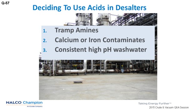
Some refiners will have a rag layer drawn on their desalters to remove an increasing rag layer volume in the desalter. At Nalco Champion, we recommend using the correct desalter emulsion breaker that will allow the rag layer volume to remain at steady state. For Nalco Champion, an increasing rag layer volume is a sign of a poor emulsion breaker selection. Our goal is to have no oil carryunder and a steady-state rag layer.
WATTS (LyondellBasell)
For our refinery, we manage the rag layer by adjusting the mix valves, washwater, and desalter chemistry to minimize the potential for oil undercarry. We don’t skim the interface to remove the rag layer. The question he is asking is: If you have a rag layer at the desalter, rather than trying to bleed it all out the bottom, do you have a skimmer at the interface to continue to remove the rag layer? And if you do that, what is the destination for that material?
BRADEN (NALCO Champion)
Good question. [Laughter] Usually the rag layer is put into a different tank, and we wait for it another day. This rag layer is normally not chemically stabilized and can be fairly easy to separate; however, it may take a secondary emulsion breaker to drop the solids and release the oil.
SAMUEL LORDO (NALCO Champion)
We are referring to what is commonly called “cuff draw”, which is a pipe located at the interface. You pull off that pipe and actually send it to a different tank, as Mike indicated. Typically, you can treat it as it goes to the tank, which is preferable, rather than building inventory in a slop tank. The reason is that it then it becomes more of a challenge to handle. You would pull the rag out of the desalter and send it to a separate tank. Sometimes it is a brine tank, so you can mix the emulsion with water and flip the emulsion a little. So, there are a couple of strategies you can utilize with the cuff draw, but they are gaining popularity with the high solid crudes.
BRADEN (NALCO Champion)
Usually that is not chemically stabilized, so it is easily separated.
ALLRED (Suncor Energy, Inc.)
I just have a quick comment about the second question. Our trigger point is 1% BS&W. So, when we run it through the centrifuge to recover the oil, we test that oil. If it is greater than 1%, we will send it back through the centrifuge. If it is less than 1% BS&W, we will send it on to a crude tank.
JAMES PROROK (Husky Energy, Inc.)
Nalco treats our desalters, and we do a draw of the cuff layer to remove iron. We still make petroleum-grade coke for anodes. So that drawing a cuff pulls out the iron. We take the cuff, which is about 10% oil and 90% brine, and send it to the free water separator, which breaks the oil and water mixture, leaving us with a high solids oil. The oil goes to a storage tank, which feeds the centrifuge. The oil from the centrifuge still has a significant number of fines. We pilot-tested a ceramic membrane for a final polishing step to get the fine solids out of the oil.
MICHAEL BRADEN (NALCO Champion)
Recovered oils in this explanation will be called “slop oils.” Slop oils are formed during the clarification of the oily wastewaters from the process units, such as desalters. These chemically induced oil emulsions will usually contain free water, emulsified water, and oil-wet solids. Emulsions of this type are very stable. Recovered oil is the oil that is separated from the water and solids from the WWTP skimmings.
The slop oils have the following characteristics: They are highly viscous, have a low API gravity, and contain 10 to 60% water and 10 to 40% solids. Oil skimmings and slop oils are hazardous and cannot be landfilled without oil reduction. Stricter regulations are driving customers to more recycling and treatment of these types of waste streams.
Typically, the BS&W requirements for recovered oil is less than 2%.
Slop oils are usually stored or used in one of the following ways: holding tanks, mixed with crude oils, incinerated, sent to the coker unit, or treated. Untreated slop oil brings lots of water into the system that may not be able to cope with either the water or the steam generated in the process. Treating the slop oils to remove the solids and water and obtaining the recovered oil is the recommended method.
Why treat slop oil streams?
Removes solids from the crude cycle;
Minimizes wastes;
Recovers oil, thus recovers money;
Restores storage tank capacity;
Oil-free solids can be incinerated at a lower cost; and,
Reduces disposal and operating costs.
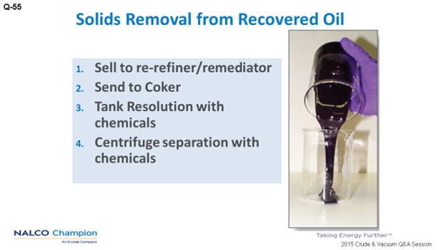
There are four options available to remove solids from refinery system:
Send the entire oily skimmings stream to the coker unit (if the refinery has one and is not producing anode-grade coke);
Send the entire oily skimmings stream to a remediator;
Chemically treat the oily skimmings onsite via a heated tank and send the rag layer to a hazardous material landfill; and,
Chemically treat the oily skimmings onsite via a heated tank and centrifuge.
All of the methods will cost money; however, the last two will bring revenue to the refinery.
There are other technological attempts to separate oil, water, and solids from WWTP skimmings. These technologies include microwave, ultrasonication, and evaporation. Unfortunately, these methods either do not resolve the emulsions or remove the solids from the crude; plus, the cost of implementation makes these methods prohibitive.
The two most common methods involve chemical and mechanical treatment of the slop oil to remove solids. Both involve chemical emulsion breakers, heat, and agitation. However, one method uses gravity separation and the other uses centrifuges and additional chemistry.
Resolving Slop Emulsions in a Tank – Gravity Settling
This method requires a heated tank and some form of agitation to thoroughly mix the chemical additive to the slop oil. Heat reduces the bulk viscosity and helps coalesce the water droplets. The chemical helps resolve the oil-in-water emulsions and water the solids. The chemical can be injected on the suction side of a transfer pump or added to the tank that has mixers. Once the chemical is mixed with the slop oil and put into a heated tank, time is needed to allow the water, solids, and oil to separate, which may take up to 72 hours or more. Warning: There will always be a rag layer. No matter how much chemical is added or how much time is allowed for separation, resolving the slop oil emulsion in a tank always leaves a rag layer. This rag layer consists of water, oil, and oil-wet solids. The recovered oil will have a BS&W of less than 2%. The water will have solids and very little oil.
So, the question that every tank breakage application must answer is: What is to be done with the rag layer? Some put it away to a holding tank to avoid the question for another day. Others send the material to a coker (if they have one onsite), and different refineries will pay the landfill costs for hazardous materials. However, the rag layer must not be removed with the oil phase since this will cause severe upsets in the desalter.
Resolving Slop Emulsions with a Centrifuge
This method is very similar to the one described above; however, the difference is that a two- or three-phase horizontal bowl centrifuge is used for the separation process. Essentially, centrifuges separate by specific gravity: solids > water > rag layer > oil. Notice that the rag layer has specific physical characteristics. Furthermore, the use of a chemical additive to that combines the rag layer with the free solids will increase the specific gravity of this mixture to greater than water. Thus, one will have solids, water, and oil separation with no rag layer.
The process is similar to the tank breakage method. Chemical addition (water-in-oil emulsion breaker), heat, and agitation is needed to help resolve the emulsion. Once the chemical is sufficiently mixed throughout the slop oil and heat applied, the slop oil is left standing for a short period of time (one to three hours). Then the stream is sent to a horizontal centrifuge for separation.
At this point, the stream will separate into four layers: solids, water, rag layer, and oil. However, the rag layer can be removed by the centrifuge by using a high molecular weight, high cationic-charged emulsion polymer. This polymer is injected into the centrifuge feed (as a 1% solution in water) “on the fly.” The polymer will combine the solids in the rag layer with the water-wet solids, thus producing a layer that has a higher specific gravity than water. When the polymer-treated stream is centrifuged, only three layers are separated: solids, water, and oil.
A three-phase centrifuge will separate solids, water, and oil into three streams. There is an inner scroll into the horizontal bowl which forces the solids to go in the opposite direction of the liquids. For the liquid phase, there is a weir placed at the oil/water interface, separating the two layers. This weir, as well as the polymer addition, is controlled by the centrifuge operator. Final results are a good cake solid, clean water, and recovered oil with a maximum of 2% BS&W. Often the BS&W is lower than 1%. The recovered oil can be blended with the desalter feed stock having very few, in any, issues in processing. The cake solids can be landfilled; and depending on the amount of oil left on the solids, can be landfilled in a non-hazardous disposal site. More importantly, the solids have been removed from the refinery cycle.
PHILIP THORNTHWAITE (NALCO Champion)
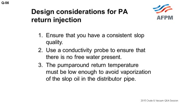
The reprocessing of recovered oils (or slop oils) through the crude unit desalter frequently results in upsets resulting in the “solids cycle” in which many refiners often find themselves. A major consideration is not to be too ambitious with the volume of recovered oil added to the crude charge since too high a level can quickly precipitate a desalter upset. It is recommended to slowly introduce the recovered oil to the crude charge while closely monitoring the desalter (e.g., try lines and the electrical system) so that any deterioration can be observed, and operational changes made to avoid an upset. However, there are some cases where “trickling” in the recovered oil is not possible.
In most cases, treatment strategies to clarify the oil is recommended, thereby resolving the complex emulsion to provide a better-quality oil that can be processed with reduced risk. It is possible to chemically treat the recovered oil with specialist slop oil demulsifiers to maximize the resolution of the complex emulsion and to drop increased amounts of solids and water in the slop tank prior to processing on the crude unit. The use of specialist solids removal additives as part of the desalter chemical program can also help to safely process the recovered oil. Not all recovered all streams can be treated chemically, and heavy, viscous emulsions will be difficult to resolve. In some cases, the only effective way to clarify the oil so that it can be processed safely is to utilize a three-phase centrifuge to separate the hydrocarbon, solids, and water. However, this is a costly undertaking and the economics of this operation have to be reviewed.
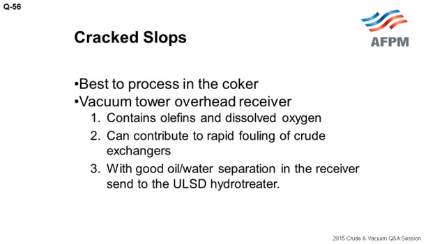
Lastly, if the refinery has a coker, it is possible to route the recovered oil directly to that unit and avoid the crude unit completely. However, this may not be possible if premium grades of coke are produced.
BRUCE ALLRED (Suncor Energy U.S.A.)
We have a leased three-phase centrifuge (oil, water, and solids) onsite, operated by a third party, which is used to separate solids from several slop oil and sludge streams produced at the refinery. Oil that is recovered from primary separation (API separators and tanks) in the wastewater treatment system is accumulated in a tank and tested for BS&W. If the BS&W is too high (greater than 1%), the oil is sent to the centrifuge. If the BS&W is low, we send the stream to a crude tank for reprocessing in a crude unit. Some would think this is expensive, but we have found the cost to be well worth it to eliminate problems with recycling and unnecessary accumulation of solids.