Question 62: When increasing the vacuum tower cutpoint, what measures have you employed to mitigate the impact of chlorides in the overhead diesel or light vacuum gas oil sections of the vacuum tower?
WEBER [Marathon Petroleum Corporation (MPC)]
Just take all of the salt out from within your desalters, and you will not have chloride problems. [Laughter] That is probably the simplest and least helpful answer. But obviously, the better job you do desalting your crude, the fewer chloride problems you will have in both towers. Short of that, the chloride issues in the vacuum tower are going to be driven by the difference in transfer temperature on your crude tower and your vacuum tower. Magnesium chloride will hydrolyze very easily and occurs primarily in the crude tower.
Calcium chloride is likely the bigger culprit in vacuum towers. If there is a 100°F difference in crude and vacuum transfer temperatures, some hydrolysis in the vacuum tower will occur. If the desired vacuum tower cutpoint can be achieved in a different way other than maximizing vacuum heater temperature, such as lowering column pressure, hydrolysis and subsequent salt formation will be reduced. Most refiners are maximizing vacuum heater transfer temperatures; so again, managing the chlorides coming out of you desalters is the key. I will note that we have seen an increase in fouling in the LVGO (light vacuum gas oil) pumps and exchangers, which is a more recent phenomenon. One item to note is that although we have not done enough work to be conclusive, we have observed more bromine or bromides when those salts were analyzed.
BRADEN (NALCO Champion)
Yes, I have to agree with John. Optimizing the desalter using mechanical, chemical, and operational analysis is critical for removing as much of the chlorides as you can and dehydrating the crude. You have a variety of options such as mixed valve studies, crude and water level controls, mud wash analysis, and washwater analysis including the pH. The refinery can also look at the overhead water and measure it for pH, chlorides, iron, organic acids, amines, cationic metals, and ionic species. Every piece of information you can gather about optimizing chloride removal is key. Then of course, the refinery should have the right neutralizer program for the chlorides in the overhead to protect from corrosion. Lastly, have a continuous monitoring program – either Pathfinder probes or some type of monitoring system of your choice – to see what is going on.
PRICE (Fluor Corporation)
I recommend you read two articles. One is NACE (National Association for Corrosion Engineers) Publication 34109, and the other is another paper from the 2013 AIChE meeting that was published by Petrobras. This paper is interesting as they have noted that although this problem has not been solved, Petrobras has seen some results with an increased fractionation reflux rate in the vacuum pumparounds to help mitigate the chloride content in the vacuum diesel. The increased reflux in the vacuum pumparounds also helps the endpoint of the distillation.
BILLS CATES (Hunt Refining Company)
Is this problem more prevalent in vacuum towers that are run wet using stripping steam versus running at a dry tower without stripping steam?
WEBER [Marathon Petroleum Corporation (MPC)]
I will say that we have seen it in a variety of towers, whether they are deep-cut or not. I think most of our towers do have stripping steam, so I cannot comment on the dry tower.
WATTS (LyondellBasell Industries)
We have not seen this issue at our refinery. A part of it, of course, starts with analyzing the crudes to know what you have and, as the other panelists said, managing your desalters and your overhead systems.
PRICE (Fluor Corporation)
The ones we know of all used stripping steam.
NAGASHYAM APPALLA (Reliance Industries Ltd.)
Sodium chloride is normally considered a stable salt. Is there a theory that, in presence of naphthenic acid, hydrolysis of sodium chloride does take place in the transfer line and leads to more chloride in vacuum tower overhead?
WEBER [Marathon Petroleum Corporation (MPC)]
I am not familiar with that theory, but it sounds possible.
PRICE (Fluor Corporation)
The following two articles may have information that will be of interest to you:
-
Gray, M. R., Eaton, P. E. and Le, T, “Inhibition and Promotion of Hydrolysis of Chloride Salts in Model Crude Oil and Heavy Oil” (Petroleum Science and Technology, 26:16, 1934-1944), 2008.
-
Gray, M. R., Eaton, P. E. and Le, T, “Kinetics of Hydrolysis of Chloride Salts in Model Crude Oil” (Petroleum Science and Technology, 26:16,1924-1933), 2008.
NAGASHYAM APPALLA (Reliance Industries Ltd.)
So, has anyone seen any correlation between the increased naphthenic acid versus the increased chloride in the vacuum tower?
RUSSELL (RUSTY) STRONG (Athlon Solutions)
Naphthenic acids will participate in accelerating hydrolysis. Literature primarily talks about it in the raw crude at the crude unit. You will likely see more chlorides in the crude unit tower and overhead, but that may also apply in the vacuum column. To respond to Mr. Appalla’s question, there is an understanding that sodium chloride is much more thermally stable than the calcium and magnesium chloride. What is not clearly understood amongst many in the industry is that magnesium chloride, when it decomposes, does not decompose from magnesium chloride (MgCl2) directly to magnesium hydroxide and hydrochloric acid. There is not a complete hydrolysis. Instead, you find an intermediate step where the magnesium becomes a hydroxylchloride. One of the chlorides is lost first, and the resultant magnesium hydroxylchloride (MgOHCl) is actually fairly thermally stable compared to the first chloride becoming HCl.
The magnesium hydroxychloride will then enter the vacuum column where it is often subjected to more severe thermal stress, still less thermally stable than sodium chloride, and will come apart. The organic/naphthenic acids will play a role in accelerating the thermal decomposition, and more HCl may be observed in both towers as a consequence.
The stripping steam: If you have velocity steam or stripping steam in a vacuum column, you most likely have a pretreated steam that has a neutralizer in it. The partial pressure of the steam in that vacuum column near the top is relatively high compared to what you see in a crude unit. As a consequence, the neutralizers involved in the stripping steam are also at higher partial pressure and can actually salt out with the chloride that is present, causing tower and top-cut corrosion and fouling.
Two of the steps that can be taken are: 1) for the vacuum column, find a way to satellite-feed your neutralizer so that the steam that gets in the vacuum column is not carrying neutralizer from the steam with it. Then, treat for pH in the overhead near the ejectors, rather than enabling steam in the tower to cause salting in the vacuum column. You will have to live with the ammonia that comes from the nitrogen-bearing crude, but you can get rid of much, if not all, of the problem by addressing the neutralizers.
JEFFREY ZURLO (GE Water & Process Technologies)
Just to add to what Rusty said, in addition to the items he talked about for changing the steam location, you can also look at what neutralizing amines you are putting into your steam system. The different amines used in the steam that can get into the crude and vacuum towers have different salt points. So that is another way to potentially control the salt fouling and corrosion in the vacuum tower.
DENNIS HAYNES (NALCO Champion)
The Best Practice is to optimize the desalter performance to achieve the best chlorides removal possible. This may include additional efforts around slop handling and better brine removal in the tank farm prior to the crude unit desalters; also, caustic use is a well-known, effective method to reduce distillation column overhead chlorides.
GLENN SCATTERGOOD (NALCO Champion)
To control vacuum tower overhead chloride concentration, the caustic injection into the desalted crude downstream of the desalter should be optimized. A quick study of caustic injection rate versus vacuum overhead chloride will provide the data necessary to determine the best caustic injection rate and help set a reasonable chloride target for the overhead. Once caustic is optimized, and during the caustic optimization step, the pH of the first dipleg condensing system should be monitored as the chloride will concentrate in the first condenser. Proper neutralization is necessary to control the corrosion in this area. Corrosion rate monitoring of the first condensing dipleg is important.
VILAS LONAKADI (Amec Foster Wheeler)
Like any other fractionator, increase the vacuum tower overhead temperature. However, this would increase the vapor load to ejector. Vacuum towers that are equipped with precondensers may be able to handle this additional load. Depending on the chlorides content and the increase in temperature, options such as operating spare ejectors, revamping ejector system, and/or adding a pre-condenser can be considered.
JOHN WEBER [Marathon Petroleum Corporation (MPC)]
Chloride salts that are not removed during the desalting process will be hydrolyzed to HCl in either the crude or vacuum tower heaters. The HCl will wind up in the tower overheads and can cause problems with corrosion or react with amines in the tower to form salts, which foul process equipment.
Obviously, minimizing salt content in the desalted crude will mitigate chloride issues in both towers and should be the primary focus for improvements. In the vacuum tower, the amount of salts hydrolyzed correlates to the difference between the crude heater temperature and the vacuum heater temperature and will be more pronounced in deep-cut vacuum towers. Mitigation of chlorides in overhead systems will be similar to control measures in the atmospheric tower.
MPC has observed salting in the LVGO circuits at several of our refineries, and it appears to be a recent phenomenon. Bromine has been observed in these salts and may be contributing to a change in salting potential in these circuits. These units run a wide variety of cutpoints and is not isolated to only the deep-cut units.
MICHAEL BRADEN (NALCO Champion)
First is to optimize the desalter via chemical program, mix valve study, crude and water level controls, mud-wash analysis, mechanical review, and a washwater analysis including pH. Second is to analyze the overhead water for pH, chlorides, and iron along with organic acids, amines, cationic metals via inductively coupled plasma (ICP) and also analyze anionic species by ion chromatography (IC). Third is to employ a neutralizer program to control the chlorides and inhibit corrosion. Fourth is to have continuous monitoring via Pathfinder®, probes, or Permasense®.
MAUREEN PRICE (FLUOR)
The hydrolysis of inorganic salts produces hydrogen chloride which will distribute between the vacuum column overhead and upper side draw(s). Improved upstream desalting and/or caustic injection can be considered to reduce the quantity of hydrolyzable salts present. See NACE International Publication 34109 for additional information. One Southern California refiner saw his chloride problem disappear after he added second-stage crude desalting.
Fluor also recommends the following paper as an excellent reference on the subject: “Mitigating Chloride Content on Vacuum Diesel” by Malheiros, et al.12 The paper notes that there is still much to learn about the subject but that a higher fractionation reflux rate has the benefit of mitigating the chloride content in the vacuum diesel, in addition to expected sulfur and end point distillation reductions.
Year
2015
Process
Question 60: Please describe your experience with the occurrence of phosphorus and barium fouling in the distillate section of the crude tower. What steps have you taken to identify and mitigate the problem?
WATTS (LyondellBasell Industries)
This slide contains our legal disclaimer. I am really not going to cover it in a lot of detail. [Laughter] Just use your own judgment.
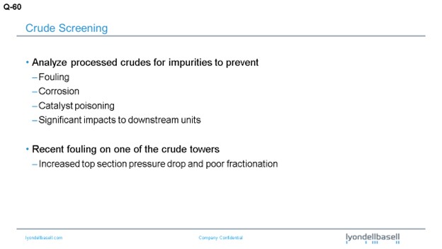
I know this topic generated a lot of discussion in our Hydrotreating session yesterday. I am mainly, obviously, going to focus on the crude side of it. I will start by saying that basically, it starts with a process to analyze processed crudes for impurities to manage and minimize fouling coming from salts, asphaltene precipitation, and other impurities.
Corrosion: Obviously, we look at TAN in the crude, organic chlorides, amines, and ammonia. We do not always do a full analysis of the crudes we are processing day in and day out, since we have a long history on those crudes. But when we are looking at new crudes, we do a more detailed analysis.
We also look for catalyst poisons mainly to make sure we do not have high levels of silica, phosphorus, arsenic, and other materials that would cause accelerated or loss of catalyst life. And then, we look at the downstream impacts on those units. But overall, our goal is obviously to manage equipment reliability and catalysts between turnaround cycles.
Last year, we took a short outage to replace a piece of equipment on one of our crude units. We were a little over five-and-a-half years into the run since the last turnaround cycle. When we started up after the outage, we saw that the top section of the crude tower dP (differential pressure) had increased to five pounds. Before the outage, it was two pounds, and that was for the top 20 trays of the crude tower. We had experience with trays fouling prior to this outage. When we would shut down the unit for turnarounds, we would see that the top six to eight trays had some fouling from salts that deposited on the trays.
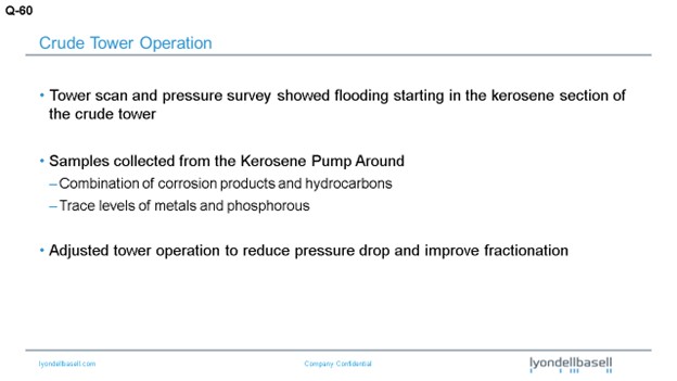
Next, we did a tower scan and also a more detailed pressure survey which showed that the liquid had started to back up in the tower just below the kerosene pumparound section. As I said, that is around Tray 20. So, as we were scanning the tower, we basically adjusted the liquid loading in the tower. We dropped the pumparound and the top reflux. Once we did that, we saw that the pressure drop returned to a normal range. The tower was no longer flooding.
Actually, prior to the outage, we had noticed an increase in fouling in our kerosene pumparound exchangers. We talked to some of the operators after we saw the increase in the tower top pressure drop. We also had some issues with valves closing when they were isolating the kerosene pumparound exchangers. So, we did an analysis of that stream; and basically, we saw a combination of corrosion products and hydrocarbons. We also saw trace levels of phosphorus as high as 800 ppm (parts per million). As I said, this occurred in April of 2014. We have continued to run the crude tower.
To manage this increased pressure drop and fouling, we have adjusted our kerosene pumparound. Before April of last year, we typically ran that pumparound at a rate of 1,300 barrels per hour or higher. Currently, we are running the pumparound at the minimum, which is 750 barrels per hour. So obviously, our kerosene production has dropped off. We have also lowered our top reflux in the tower and adjusted the heater outlet temperature and stripping steam to the tower to reduce the vapor load for certain crudes.
We have a planned outage for the first quarter of 2016 as it will have been a little over seven years since the last turnaround. We worked with a company to redesign the trays, so we plan to replace the trays. During the outage, we will also be able to verify the fouling.
BRADEN (NALCO Champion)
We have conducted deposit analysis on samples in the jet kero (kerosene) trays and found that the phosphorus component in the deposit, along with the iron and sulfur. The phosphorus usually comes from an upstream additive that is used in the fracking aspect of water-sensitive clay formations. They use a mono- and diphosphate ester to help with the fracking process that can be complexed with an inorganic material and removed from the crude oil. During the manufacturing of the mono- and diphosphate esters, a triphosphate ester is also formed which is oil-soluble and cannot be complexed. The triphosphate ester is the material coming in with the crude once it passes through the desalter. But once it gets into the heat exchangers into the towers, it starts decomposing. It starts hydrolyzing to phosphoric acid. So essentially, phosphoric acid distills up tower, deposits onto the tray, and then precipitates at the jet kero trays. When the phosphorus-containing deposits increase in size, the deposits then begin closing the holes in the trays.
Some refiners will replace the trays with trays containing larger holes, therefore allowing you to get more flow in the jet because the jet fuel has a phosphorus spec. Essentially, we try to mitigate the phosphorus from distilling up the tower by injecting a chemical additive that complexes the phosphorus to keep it into the resid fraction and does not distill up the tower. So, if you want to know a little more about that, contact your chemical vendor.
WEBER [Marathon Petroleum Corporation (MPC)]
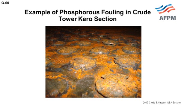
We have had some practical experience. The picture here shows phosphorus fouling of one of our crude towers. This is in the kerosene section again. The first time we experienced it in 2011, we went into a tower for turnaround and found fouling in the kero section, with none above or below. It had not caused an operational problem, and we actually did not analyze foulant that was on the tray at that time.
At another MPC refinery, the crude unit was reduced, for economics, for roughly a month. When an attempt was made to return the unit to full rate, flooding was observed in the kerosene section. We were referred to the Canadian Crude Quality Technical Association (CCQTA) which immediately said, “Oh yes, you have phosphorus issues.” After further discussion, it was discovered that CCQTA has extensive experience with phosphorus contamination. Their website indicates that since 1995, they have had a project on phosphorus fouling and have worked with some of their producers to help minimize it.
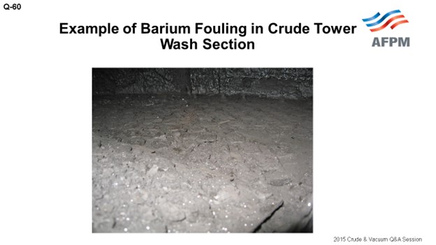
A similar incident occurred at a third refinery. One of the remedies we have implemented is the installation of fouling-resistant, fixed-valve trays in the kero section. In refineries that still have floating valve trays, we try to keep vapor traffic up in the kerosene section. We have found occasions where the valves were found stuck open; but fortunately, they did not cause an operational issue. It is when we got lower rates and lower velocities that the valves became stuck closed and caused flooding problems. We have also had experience with barium fouling in the wash section of the crude tower. This picture shows an example of that problem. The solution for this issue was also to install foul resistant, fixed-valve trays.
NAGASHYAM APPALLA (Reliance Industries Ltd.)
Is there an industry-accepted limit of monitoring the phosphorus in the crude oil? If so, does anyone distinguish the differences between volatile and non-volatile phosphorus?
WATTS (LyondellBasell Industries)
I want to echo some of what John said. I did quite a bit of research on this and know that it is not a new issue. I think the slides I found were from the mid-1990s, and the specification levels I saw were 1 to 1.5 ppm. But based on our working with our lab, we have not seen a detectable level of phosphorus on the crudes we have analyzed. We have not traced it back to a crude source.
BRADEN (NALCO Champion)
In our experience, the phosphorus compounds enter the refinery via the crude and normally come in slugs because of the fracking issue; and therefore, it can be up to 50 parts per million when you get a slug of phosphorous material. But in our measurements of it, it is normally 1 to 3 ppm. We have run that by ICP (inductively coupled plasma) analysis. So it is normally very, very low if it is in there. But sometimes, you do get slugs. Then when do you catch a slug? When do you see that? You just see the results of the slug coming through. It is hard to pick up.
NAGASHYAM APPALLA (Reliance Industries Ltd.)
What is the industry’s experience on the cause of this fouling when using high temperature corrosion inhibitors in atmospheric tower?
SAMUEL LORDO (NALCO Champion)
The inhibitors that are used for high temperature treatment are not really part of that particular description. As Mike indicated, those are triester compounds which come in with some of the fracking gels that are used in Western Canada or in clay formation-type crudes where they are water-sensitive. In the lower 48 though, there is no fracking with phosphorus-based gels. Now we are targeting to look at phosphate esters being used for scale control and corrosion inhibitors.
I looked at one complete year of a refinery’s crude tracking where they analyzed for phosphorus the entire year on each batch that came in. Most of it was in the 1 to 3 ppm range; except in November, it shot up to about 10 to 15 for a one-month period. And then, it came right back down. During that timeframe, their tower had some issues which have not yet been resolved. So they will have to come down and clean it. But as far as the inhibitors go, most of them do not cause a problem. If you overtreat, then yes, you can have some issues.
PRICE (Fluor Corporation)
Just a comment to the Mr. Appalla from Reliance: If you have not visited the CCQTA website, I recommend that you do because it contains is a lot of information about lab methods that might be helpful.
NAGASHYAM APPALLA (Reliance Industries Ltd.)
Yes, but the CCQTA only talks about the phosphorus coming from the Canadian crudes. Suppose you are not processing Canadian crudes. What are the other sources of it?
HAROLD EGGERT (Athlon Solutions)
It is an odd question when you say barium and phosphorus in the same sentence. Why would you pick those two particular elements to examine? Like Sam, and I think the panel, have mentioned, not all phosphorus is going to end up fouling your trays. It is always coming in at a low level. Some of it is benign phosphorus, and some of it will contribute to tower fouling. What is currently being used – and the reason the barium came up – is that the phosphorus causing some of these problems is injected to prevent barium sulfate scale upstream. It is a scale inhibitor. If you see barium and phosphorus, chances are it is from the production chemicals. The barium used to be called NORM: Normally Occurring Radioactive Material. That is why we are looking for phosphorus and barium. It is the combination of the two that sends up a red flag.
JEFFREY ZURLO (GE Water & Process Technologies)
Just to clarify, you are right. The CCQTA talks about phosphate esters from Canadian crudes. One of the test methods they have on their website specifically identifies volatile phosphates. The CCQTA test separates the volatile phosphorus components from just the general phosphate components by performing a distillation on the whole crude and analyzing the middle distillate cuts. Although the CCQTA work is done on Canadian crudes, the source of the crude oil really does not matter. What is important is if phosphate is in the crude; if it is volatile; and, if it can hydrolyze, complex, and form this fouling material. So, it is not necessarily the source but more the effect of what type of phosphate is in the system.
BILLS CATES (Hunt Refining Company)
If I understood the question, what Mr. Appalla is really asking is: Other than light tight oils, where are they finding crudes containing phosphorus? He just really wants to know what crude; he does not want to buy. [Laughter]
WATTS (LyondellBasell Industries)
I mentioned earlier that we have not traced it back to its source, at least in our refinery.
BRADEN (NALCO Champion)
The phosphate esters for the fracking are mainly coming from the Canadian side, the north coast of North America, and the south coast of Canada.
JESSICA NAQUIN (Valero Energy Corporation)
I have heard rumblings that the fouling would have less affinity for metallurgies. For example, if you have carbon steel or different variations of stainless trays or parts in the tower, sometimes the phosphorus fouling will not have the same affinity; so then, you will not have the same accumulation of the fouling in the tower. Does anyone have experience with those observations and any Best Practices?
WATTS (LyondellBasell Industries)
I do not have experience on the metallurgy. I would say that what we are doing is similar to what John said in that we redesign the trays to go to a fixed valve. So, we avoid the potential – if you turn down, increase, or shut down a unit – of your valve getting locked in place; that is, if you have a floating valve. Obviously, that changes your flexibility on how you can run the crude unit when you turn down rates.
PRICE (Fluor Corporation)
Once again, I am not an expert on this subject. Based on the experience of our clients, I think the jury is still out on the subject of phosphate fouling. People are finding, in some cases, that when they solve the fouling problem in their crude tower, the fouling problem migrates downstream to the exchanger. While exchanger fouling is not a good problem, it is solvable. If you can then install a bypass and if you have the ability to do online cleaning of that exchanger, it will help to mitigate the impact on your unit throughput.
RALPH WAGNER (Dorf Ketal)
Fouling in the distillate section of the crude tower due to phosphorus is rising globally. A primary likely cause is the result of phosphorus-containing chemicals used in oil exploration and production. However, in recent surveys, several of the fouled towers have employed naphthenic acid corrosion inhibitors which have contributed to the problem.
The corrosion inhibitors contain phosphorus, and most products are thermally unstable and contribute foulants to the system. A Best Practice is to use a thermally stable inhibitor containing a phosphate triester. This type of corrosion inhibitor can withstand processing temperatures and does not contribute to phosphorus fouling. By comparison, mono and diphosphate esters are prone to thermal degradation; products of decomposition contribute to phosphate fouling.
For barium, we have observed issues in desalters, preheat exchangers, and towers due to presence of barium in the crude. The presence of barium appears to depend on geographic location and how the well has been fractured. Bentonite clay used in oil well fracturing contains barium, and poorly fractured wells may allow this clay into the crude. Barium is not soluble in oil or water, and the small particle size leads to accumulation in the rag layer in the desalter. Steps to mitigate barium accumulation include the reduction of pH and the optimum selection of desalting chemicals and mechanical adjustments for minimizing rag layer.
JOHN WEBER [Marathon Petroleum Corporation (MPC)]
MPC has experienced fouling in the kerosene section of crude units at multiple refineries which has been attributed to phosphorous. The first documented occurrence was found in 2011 during inspection of the tower during a unit turnaround. A light crusty scale was found on the trays in the kerosene section with no fouling in the sections above or below. Although this scale was not analyzed, subsequent incidents support phosphorous as the culprit.
A second occurrence followed an extended rate reduction at another refinery. When the refinery attempted to return to maximum rates, they were limited by flooding in the kerosene section. The MPC Crude Quality Manager at the time had heard of similar issues and referred the crude technologist to the Canadian Crude Quality Technical Association (CCQTA). The CCQTA representative suggested phosphorous fouling as the potential problem based on experience with other refineries. An attempt to remove phosphorous with online chemical treatment showed some effectiveness, but the unit was ultimately taken down to clean out the fractionator concurrent with a planned turnaround. The valves on several trays in the kerosene section were found to be stuck closed, which caused the flooding issues in the tower (See Figure 1). Analysis confirmed phosphorous as a major component of the foulant. Similar fouling has been found in one other refinery on inspection, however the valves were stuck open versus closed and did not impact operation.
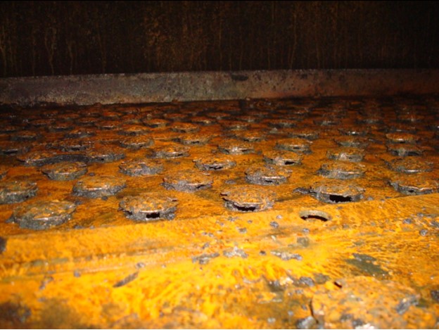
Figure 1. Example of phosphorous-induced tray fouling in crude unit kerosene section
The CCQTA website indicates that the group initiated a project in 1995 because of phosphorous-related fouling at three Canadian refineries. The source of the phosphorous was traced back to additives used in the production industry.
MPC has switched to fouling-resistant, fixed-valve trays in crude towers where phosphorous fouling is thought to be an issue. In addition, at a refinery where we have not been able to replace trays yet, efforts are made to keep traffic high in the kerosene section in the event of a rate reduction.
MPC has also experienced fouling attributed to barium at one refinery in the wash section of the crude tower (Figure 2). Fouling-resistant trays were installed to minimize fouling rate and extend time between cleanouts.
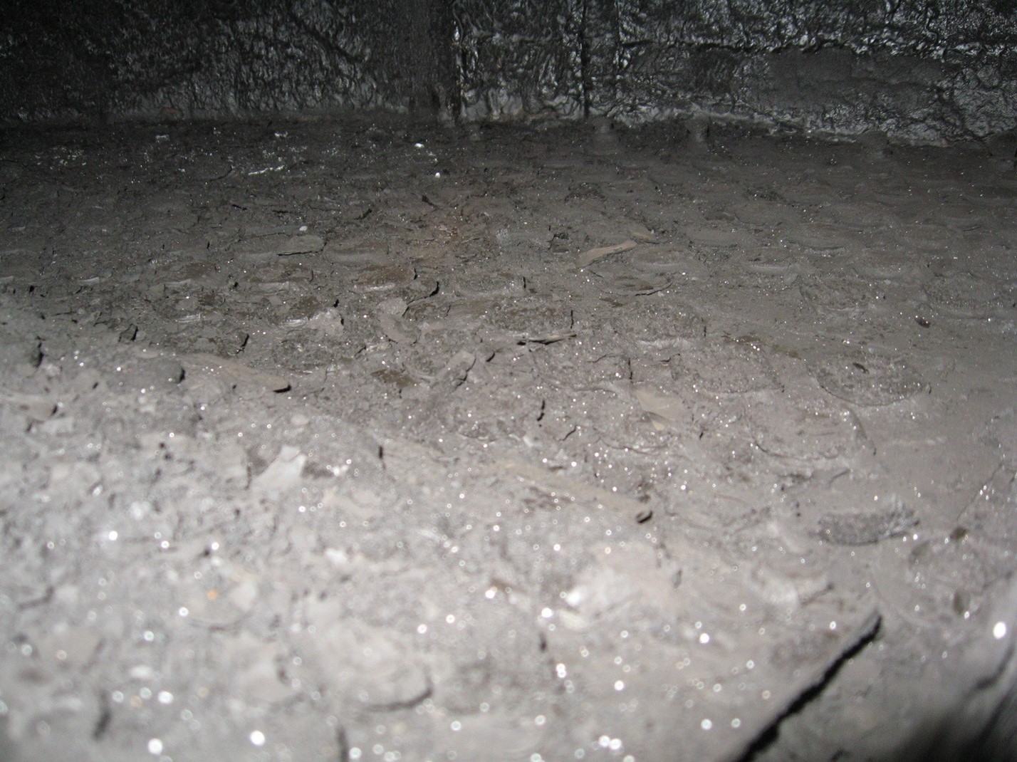
Figure 2. Barium fouling in wash section of atmospheric crude tower
MICHAEL BRADEN (NALCO Champion)
Deposit analysis of the jet/kerosene trays in the distillation towers has shown that phosphorus can be a component in association with sulfur and iron. The phosphorus usually results in the use of a chemical additive in upstream applications, such as a part of a corrosion inhibitor, or present in downhole fracking fluids. Phosphorus-containing additives are also used as fouling inhibitors for barium sulfate.
The downhole applications use mono- and diphosphate esters that can be removed by coagulation via inorganic chemicals. Unfortunately in the manufacturing process, triphosphate esters are also formed, are oil-soluble, and cannot be removed by the coagulation mechanism. Thus, the triphosphate esters move through the refinery’s desalters and are in the crude entering the distillation towers. At this point, the higher temperatures begin to hydrolyze the triphosphate esters converting to it to phosphoric acid, which then distills up the tower and condenses at the jet or kerosene sections. The acid reacts with the iron and sulfur causing corrosion to occur. Overtime, the deposit is large enough to block the holes in the trays. At this point, the tower needs to be shutdown to remove the deposit.
There are chemical additives which are used to complex the phosphoric acid generated and keep the phosphorus in the resid. Please consult your chemical supplier.
Another method to mitigate the fouling is to install trays with larger holes; although this will not decrease the fouling, it will lengthen the run time for the tower.
EDWIN WATTS (LyondellBasell Houston Refining)
It is important for refineries to have a rigorous program to analyze crudes, particularly new crudes, for impurities that will cause issues on the crude or downstream units. Recently, we experienced fouling in the kerosene section of one of the crude units. A sample from the kerosene pumparound exchangers showed a combination of hydrocarbons and corrosion products. There were trace levels of metals and phosphorous. We have made adjustments to unload the top section of the tower to minimize flooding, reduce pressure drop, and improve fractionation. We will verify the fouling mechanism during an upcoming turnaround.
MAUREEN PRICE (FLUOR)
Phosphorus originates mostly from secondary recovery processes and causes severe fouling in the jet pumparound (both trays and exchangers), jet product route (exchangers), and in the jet-diesel fractionation section. There have been problems with some Canadian and fracked crudes, as well. Fouling-resistant trays, such as PROVALVES, have been effective (at least in some cases) in alleviating the problem in the tower but have aggravated the problem in the exchangers. Bypasses permitting cleaning exchangers when the plant is running have been very useful, but beware of design conditions. It is difficult to predict the offending crudes as the amount of phosphorus is usually small in them. The deposits often show 10 to 50% phosphorus. However, one Southern California refiner who runs 20% Canadian crudes has no evidence of any phosphorus fouling. Barium fouling has been experienced by another client.
CCQTA has established a limit of maximum of 1.5 ppm volatile phosphorus after conducting research. Their website has a large amount of information available, including test methods.
Year
2015
Process
Question 63: What type of facilities have you used to cool hot vacuum residue going to storage to avoid plugging problems and facilitate reprocessing?
WATTS (LyondellBasell Industries)
I am going to focus on the system we have and also some of the issues we have experienced. The majority of our resid that is produced off the crude unit vacuum towers is sent through the hot resid system straight to the cokers. We have two crude unit trains. We process 120,000 to 140,000 barrels per day of crude on each unit. We have two cokers. Each coker has four drums. One coker can process up to 40,000 barrels per day of resid on a four-drum operation. The other can process 60,000 barrels per day of resid on a four-drum operation.
Our cold resid system is where we send excess resid, but we also maintain that system during normal operation. So, what we do is take uncut resid at about 400°F+ and add cutter. A base cutter for us is heavy cycle oil from the FCC. That is typically the only place we send it. Then we make up, as needed, with distillate-range material. The majority of the time it is LCO from the FCC. Basically, we target a maximum tank temperature. We have a temperature limit of 210°F, so we try to keep it around 200°F. When we are stacking a lot of resid, we can hit a viscosity spec. We have found that we need to add about 30 to 40% cutter to hit that spec.

We have three main modes of operation. The first is typically the mode in which we operate. I call it ‘resid system balanced’. Basically, this is where the coker is pacing the cold resid. So typically, we are sending 6,000 to 10,000 barrels per day to tank and pulling that equivalent amount back to the cokers.
We have what I call ‘resid stacking mode’. With the current system, we can stack up to 30,000 barrels per day of resid with a minimum of 30% cutter. That leaves about 21,000 barrels per day of resid you can stack.
The last mode, which we do not do very frequently, I call ‘resid pull’. Typically, this occurs after a short outage of the cokers. After the outage, we will pull back resid that was stacked. Occasionally, the economics support going out and purchasing resid, but the way our refinery operates is that we are typically close to limits on the cokers when both crude units are at full rates because the resid yield is typically above 30%.
The last piece I want to talk about is basically how we minimize the potential for resid line plugging; basically, it is managing the temperature. As I said, we have limits on what we can send to the tank, but we operate in a relatively tight window. We try to keep the temperature above 190°F. Basically, we have added in the orders for the console operators that one time per shift, they need to heat up the cold systems. So, they do that about twice per day. Resid, as I am sure a lot of you are aware, is hard to meter. So basically, what we have done, based on operating experience, is set minimum valve output limits where we are all alarmed if the resid rate gets too low. That is based on historical information. So, for us, the biggest challenge for managing the hot and cold resid system is during major upsets when we lose production of our main cutter source and significant coking capacity. This is typically where one or more of the cokers go to a two-drum operation. That is where we are most likely to have issues with plugging in the sections of the hot or cold systems.

In fact, back in 2010, we had a refinery-wide emergency shutdown. We actually plugged up the hot system between one of the crude units and the cokers. It took a lot of money and time to unplug that system. Last year, we also plugged up a small part of the cold system. The highest risk for us is when we have a major refinery outage because multiple assets or operating teams have to communicate with each other to make sure we get cutter in the lines.
PRICE (Fluor Corporation)
I want to second what Ed said: The challenge of storing hot resid is very difficult, although folks who make asphalt and store it have more chances to do this than others.

To overcome the difficulty in storing hot resid, many refiners in Southern California will use box coolers, diversion air coolers, or a tempered water bath. Normal cooling water cannot be used because it will cause extreme fouling on the water side, as well as plugging on the hydrocarbon side. The diversion air coolers incorporate special design features to ensure that the approach to pour point is adequate to prevent plugging on the hydrocarbon side. On an emergency basis, quenching with cold gas oil product is about the best option you have.

EBERHARD LUCKE (CH2M Hill)
I do not know if you mentioned this; but if you did, I apologize for making you repeat it. When you process cold vacuum residue in the coker unit, because of heat integration and the amount of cutter stock you need, do you have a limit, such as a percentage of total fresh feed, up to which you can process?
WATTS (LyondellBasell Industries)
A typical operation is where I would, say, pull less than 10,000 barrels per day out of 90,000 barrels. I know that we pulled quite a bit more than that in the past – up to 20,000 barrels, or somewhere in that range – out of 90,000; so, a little over 20%.
JAMES DOHERTY (LyondellBasell Industries)
To add to the point and answer the question, I work on the cokers with Ed. We would hit that limit. Sometimes, right before we got to that limit, we would see increased foaming on the cokers. That would limit our pullback instead of a heat limit.
WATTS (LyondellBasell)
I want to comment on what Maureen mentioned. I did not really add detail to how we cool off our resid. We add cutter. We have cooling water exchanges on the crude units. But a couple of years ago, we installed a temporary cooling system just before we sent the resid to the tank. We actually cool off the resid with glycol. That is a much better system, in terms of reducing exchanger fouling. It allowed us to reduce our cutter significantly and also to stack more resid. With that system, we were able to stack as much as 40,000 barrels per day of resid. Without that system in place, we were limited to somewhere around 20,000 barrels per day.
VILAS LONAKADI (Amec Foster Wheeler)
In most cases, vacuum residue is cooled with the incoming feed to a crude unit or other streams that require heating. Other facilities employed are the use of steam generator or tempered water system. Viscosity, and pour point of vacuum residue, along with the design temperature of the storage tanks, tracing of the product rundown line, type of heating facilities for storage tanks, and storage duration should all be taken into consideration when deciding the storage temperature and design of the associated facilities.
EDWIN WATTS (LyondellBasell Houston Refining)
There are several different system designs that are used to manage excess resid produced off the crude units. Our excess resid is mixed with a cutter stock and cooled to about 200°F using cooling water exchangers prior to going to storage tanks. The cutter is a combination of FCCU heavy cycle oil and distillate range material. The resid is either sold or pulled back to the cokers as feed. It is important to maintain adequate flow, temperature, and cutter to prevent the system from plugging up.
MAUREEN PRICE (FLUOR)
Ideally, hot vacuum residue is cooled through the preheat train to about 400°F before being sent to a storage tank that is designed for this hot temperature and in accordance with the codes and standards which can present a challenge. To overcome the design challenges of storage at (or near 400°F), a box cooler, diversion air coolers, or a tempered water bath can be used. The use of normal cooling water is not recommended (due to the risk of extreme fouling on the water side AND plugging on the hydrocarbon side). Diversion air coolers incorporate special design features to ensure that the approach to pour point is adequate to prevent plugging on the hydrocarbon side. For emergency rundown, the hot vacuum residue can be quenched with cold gas oil product to be sent to a storage tank for reprocessing.
Year
2015
Process
Question 64: What are acceptable makeup water streams that can be used for coke cutting which will not affect the coke quality?
MAYO (CITGO Petroleum Corporation)
With regard to coke quality, a lot of the available streams are acceptable. A few of the additional considerations to take into account are: Is this makeup water stream going to add overall load to my wastewater treatment facility? Is this new water? Is this water that I can recycle? Streams that are acceptable are: stripped sour water. If you are not reusing this water at your desalters or FCC wet gas scrubbers, then it would be an acceptable stream.
Refinery effluent water: If you have treated water that is nice and clean, consider hydraulics which allow you to bring it back to the front, if that is feasible. Waste heat boiler blowdowns and cooling tower blowdowns are the streams that are wasted from other processes and typically just sent to the wastewater treatment facility. So, after you look at your recycles, you can obviously go with well water or river water systems, if your water quality allows.
From a quality standpoint, refiners should be monitoring the TSS (total suspended solids) on their cutting water. This comment is just a reminder to people to make sure they consider the TSS of their makeup stream to ensure it does not cause the TSS of the overall stream to increase above the manufacture's recommendation. Make sure that the stream you bring in will not cycle up that cutting water system. Most of the cutting tool manufacturers suggest staying under 2,000 ppm TSS to minimize the erosion on your cutting nozzles. So that is a consideration to take into account. And then naturally, any of the bad contaminants in your water stream should be evaluated and reviewed with your Environmental group: You do not want to bring in any makeup streams with hydrocarbons or any other contaminants that will give you air quality issues.
EBERHARD LUCKE (CH2M)
The answer to this question depends on the type of coke that is produced in the unit. Anode grade coke and needle coke production have much higher requirements regarding coke quality than fuel grade coke production.
For fuel grade coke production, I have seen many units using stripped sour water as makeup water for the cutting system. In some cases, there were more concerns regarding the impact on the hydraulic cutting system itself (corrosion) than on the coke quality. The quality of the sour water also depends on the type of crude oil that is being processed in the refinery. In some cases, stripped sour water was rejected as cutting water makeup due to the high level of contaminants that were not stripped out of the water.
For anode-grade coke production, stripped sour water may still be suitable as makeup water, depending on the type and quantity of contaminants that can be expected.
VILAS LONAKADI (Amec Foster Wheeler)
The selection of makeup water streams for coke cutting is made based on the quality of the streams. Traditionally, non-phenolic stripped sour water or utility/raw water has been used as makeup water. In terms of quality, the H2S Content, pH, chloride levels, total solids content, CaCo3, in terms of hardness and alkalinity, need to be monitored for the makeup water and decoking water to the required levels. These qualities of the makeup water affect more – in terms of the material selection for the downstream equipment such as coke cutting pumps, quench water pumps, pipelines, odor, and environment – rather than the quality of coke itself.
BRENT MAYO (CITGO Petroleum Corporation)
With regard to effects on coke quality, most available makeup water sources are acceptable. The makeup water stream should be evaluated to determine if the source would create “additional” water that would increase hydraulic load on the wastewater effluent treatment facility. Next, prioritize the available streams based on your facilities’ quality, starting with the cleanest options. Examples are:
-
Stripped sour water [if not already in use at desalters or FCC WGS (wet gas scrubber)]
-
Refinery effluent,
-
Waste heat boiler blowdown,
-
Cooling tower blowdown, and
-
Well/river water.
When evaluating available water sources, quality concerns can include:
-
Low Solids: Ensure that the makeup source keeps the overall cutting water TSS below 2000 ppm (typically recommended by the cutting tool manufacturer to minimize erosion of cutting nozzle).
-
The Absence of Hydrocarbons: Potential oily water sources should not be used to avoid emissions and downstream emulsions that may be difficult to separate. Prior to making any changes, verify your coke product specifications to ensure that changes in coke quality will not affect your ability to sell the coke.
Year
2015
Process
Question 68: How does your organization share operational and process safety information to foster an environment of continuous improvement?
LARSEN [Marathon Petroleum Corporation (MPC)]
I am going to put in another plug for an AFPM tool: the AFPM Safety Portal. The FCC Advisory Group at Marathon uses this portal to share information among our different unit engineers and refineries. I know that Marathon, as well as many other companies, submits process safety data there. I think it is a good tool to use. So, if you are not already using it within your organization to learn, you should take advantage of it.
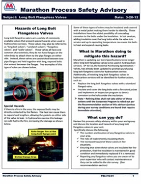
I also would like to touch on Marathon’s Process Safety Advisory Program. Our program was modeled after the “Safety Beacon” of CCPS (Center for Chemical Process Safety). The document is just one page and can be printed on the front and back, if necessary. It is important that this bulletin be presented with an eye-catching layout and contain a concise listing of high-level learning events. Basically, it is just a brief, fact-based summary of the incident. We work to tailor the handout to contain a section describing what you can do in your position in the refinery to prevent incidents, whether internal or external, to Marathon and including information you can learn from these types of events.
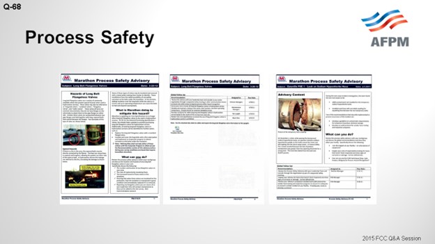
On the next slide, you see a couple of examples; nothing fancy. One of them dealt with long-bolt flanges.
We try to do only one of these per month within our organization. It gets rolled out at refinery-wide Safety meetings and reviewed with every level of an affected organization face-to-face. So I think it is definitely a good learning tool. One of the challenges associated with it, for us, is making sure we use a well-credentialed employee to generate these documents. It should not be done by a junior person. You want someone who is recognized as having subject matter expertise about making these types of process safety advisories that have worked well for us. So that is one of the highlights of our Process Safety program that I believe works well for us.
FOSHEE (Shell Global Solutions - US)
Thanks, Nik. Sharing operational and process safety information begins with the mindset of Goal Zero: Operate our facilities without significant incidence or fatalities. This is documented in our HSSE (Health, Safety, Security, and Environment) and social performance framework which communicates and shows commitment to safety and has policies, standards, and manuals that contain mandatory safety rules for all Shell employees, joint ventures, and contractors to follow. These manuals cover topics such as health, process safety, environmental projects, contractor HSSE management, personnel safety, security, product stewardship, transportation, and social performance.
In order to further reinforce the safety mindset at Shell, we have “The 12 Lifesaving Rules” which are mandatory and cover personnel safety. Three Golden Rules within Shell to help reinforce expected behavior for our employees are to comply with governing laws, standards, and procedures; to intervene in unsafe and non-compliant situations; and, to respect our neighbors. In addition, all Shell employees take mandatory safety training on a frequent basis. Finally, there is an annual event that we call Safety Day where all Shell employees take a pause to reflect on their personal commitment to safety.
NIKOLAS LARSEN [Marathon Petroleum Company (MPC)]
MPC utilizes the AFPM Safety Portal to communicate and share experiences and knowledge within our FCC Advisory Group. It is a vital component of our goal to improve process safety performance. We also have a Process Safety Advisory Program to learn from external industry and internal MPC process safety events, significant near misses, and high value learning events. Our Process Safety Advisory Program was modeled after the Center for Process Safety (CCPS) Beacon and is a tool for the broad distribution (all MPC refining sites) and discussion of significant external and internal process safety events and high value learning events (significant near misses).
Key Features of the Process Safety Advisory Design:
-
Eye-catching, professional layout
-
Short: 1 to 2 pages (If two pages, then print on the front and back.)
-
Brief, fact-based description of the incident written in common terms
-
Key findings from the incident investigation
-
“What can you do?” section targeted for work group discussions that start with the Refinery Leadership Team and cascade down to every affected work group at the site; points in this section guide the group to explore their vulnerability to a similar incident and to take action to prevent an occurrence at their site.
-
Global Follow-up section targeted at close gaps in management systems, programs, and performance at all sites which is assigned to a responsible manager with a due date and which is put in the MPC Recommendation tracking system to follow through to resolution.
The workflow of our Process Safety Advisory Process for internal events starts with a Root Cause Incident Investigation being completed along with a first rough draft of the PSA (for external events, the corporate Refining group will compile information and generate a draft PSA). This is forwarded to the corporate Refining staff where it is reviewed. The final version of the PSA is reviewed with all refinery site managers and cascaded through the organization as a part of a sequential or other Safety meeting. Recommendations are tracked to resolution and reported quarterly in the corporate refining PSM (Process Safety Management) report. PSAs are then also connected into the PHA and Refining Standards Updates process.
Benefits of the program include:
-
Provides a high impact requiring minimal resources,
-
Creates an effective means of communicating with and engaging employees,
-
Closes the gap at all refining sites, not just at the affected site,
-
Facilitates learning and improving Process Safety Hazard Recognition,
-
Offers a robust means to follow through on Global Gaps, and
-
Permits us to be well poised to take incidents from the Industry Event Sharing Program.
Key success factors of the program include that we:
-
Get top-down buy-in on global follow-up recommendations,
-
Do not overload the sites with too many PSAs because MPC’s experience is no more than one per month, and
-
Do not assign the PSA final drafting to a junior employee because the final drafting requires a “been there, done that” experience level.
Year
2015
Process
Question 67: The industry continues to experience process safety incidents associated with FCC electrostatic precipitators. What are you doing to prevent these incidents?
REYNOLDS (Phillips 66)
Phillips 66 has six ESPs (electrostatic precipitators) in service. We have not been immune to serious incidents on our ESPs. In 1994, we had an ESP explosion, which led to a fatality. So, in order to minimize the likelihood of these kinds of incidents happening again, the company has a standard that all of the refineries are required to follow. It lays out how your safety system is supposed to be configured and which features it is supposed to have. The compliance of the standard is tracked at the corporate level, so all of the refiners have to report if they continue to meet the standard. We have one wet ESP that is downstream of the scrubber, and it must meet the compliance just like regular ESPs.

One of the features required by this standard is that the ESP shall shut down if the main FCC safety system engages or trips, regardless of the cause. There are several other features. If the inlet CO (carbon monoxide) level exceeds the prescribed limit in the standard, which says that it can be no greater than 5,000 ppm (parts per million) of CO, the safety system engages. Also, if the air preheater has a safety system on it which then trips, the ESP is required to trip along with it. The ESP must have its own separate shutdown button. The CO is used basically as a surrogate for other combustible material. CO is combustible itself; but if you are having poor combustion in your regenerator, you are likely to be generating CO as well. One of the more important features is that the ESP cannot have the capability to re-energize itself after it trips.

So the highest potential for operating on ESP and explosive composition in your flue gases during startups comes from the use of torch oil along with air preheaters, which can lead to poor combustion. Our recommended practice is to keep the ESP down during startup until the unit is stable. Stability is defined as feed in the unit, stable pressure balance, CO within limit, and nothing bypassed in the safety system. For certain locations, you may not be able to have the luxury of starting up without ESPs. So if you do that, the standard recommends that you have an air preheater safety system as well.

The standard includes some recommendations; for instance, minimizing the personnel around the ESP when you start up or shut down or if there is an upset. It also recommends utilizing the methane analyzer in conjunction with the CO analyzer. And for the sites that do start up with ESP online, having a methane analyzer – in addition to a CO analyzer – is strongly recommended. The standard includes some scenarios you must consider whenever you do a PHA (Process Hazard Analysis), such as the loss of combustion air or any kind of upset in the regenerator, upset in the stripper, low-riser outlet temperature, and pressure reversals. A lot of the information I used for today’s responses came from a presentation by Phillips 66’s own Mike Wardinsky at the 2009 AFPM Q&A Principles & Practices.
LARSEN [Marathon Petroleum Corporation (MPC)]
In Marathon, we have two units with ESPs on them. Our setup is very similar to what Mark described with Phillips. Any activation of the normal FCC SIS (Safety Instrumented System) will de-energize the ESP. On the slide, you can see some of the limits that we use. Our trip point for CO is 1500 ppm, which is a little more conservative. Also, we will trip the ESP if excess oxygen is less than 0.1%. So, either of those inputs will act to de-energize the ESP. For safety purposes, we only run our ESPs energized during stable normal operations, not during the times of hot standby or startup, etc.

A lot of thought can go into the selection of the right number to use for de-energizing the ESP. An example is the chart on the next slide which includes some numbers, based on the molecules and some inflammability assumptions. This is an example, published by Thomas Lugar at GE1 in 1992, which shows you the magnitude and framework of the danger zone for CO in relation to ESP operation. So, with that, I will put in a plug for our Principles & Practices session tomorrow. I believe it has a topic on ESP safety as well, which will be discussed in more detail tomorrow morning.

KEVIN PROOPS (Koch Industries, Inc.)
Mark and Nik, thank you for your comments. I had the misfortune of visiting the unit Mark mentioned about the week after that catastrophe happened. I want to add a couple of comments to what you described during the startup (when that explosion occurred). Natural gas backed in from the fractionator, through the reactor, and got all the way to the regenerator. I believe that there would not have been any significant CO at that time. Oxygen was high.
So panel members and the audience, if you are worried about ESPs on startup, recognize that they can be very abnormal to what you are used to seeing. I believe the incident investigation also found that the ESP had been in a de-energized state, but it still exploded. So, you have to watch out for potentially explosive mixtures of oxygen and methane at higher temperatures.
ROGER LANOUETTE (Monroe Energy, LLC)
I am curious about the shutdown system. Our analyzer people are telling us that there is interference with CO and methane in doing the analysis and calibration difficulties. Is there a specific analyzer that you have come across that is better for this kind of service? The second part of this question is: Is this an SIL (Safety Integrated level)-rated shutdown system?
UNIDENTIFIED SPEAKER
As far as the analyzer, I cannot speak to what works better in others. I do not think we have a standardized analyzer as far as I know. Do we?
LARSEN [Marathon Petroleum Company (MPC)]
My answers will be published in the final Answer Book. In them, I have detailed the specific analyzer we use. I know a lot of folks are going to the TDL (tunable diode laser) technology, which is a question later on. I think we will talk about response time in Question 76 in a little while, too. I can meet with you after the session to go over the specific analyzer we use with good success.
EMERSON FRY (Delek Refining, Ltd.)
Does anyone have any experience or insight as to whether or not this would be important to have in a partial-burn unit with a CO boiler on the backend? Is that at any greater or lesser risk than a full-burn unit?
J.W. BILL WILSON (BP Products North America Inc.)
Just to add another question about it, is there greater risk with an ESP and CO boiler or is the risk the same? It is at least the same. Okay. We actually managed to blow up an ESP that had a CO boiler on it, so the risk is there. So yes, I certainly think the standards will be the same on our units. I imagine other people who have standards will probably apply the same standards.
RIK MILLER (Phillips 66)
I will address two issues. One is the analyzer. As Nik said, the Phillips 66’s standard also calls for TDL analyzers because they are very fast-responding and very accurate and sensitive for CO. You can also get a TDL for methane. Some of our units have that as well.
As Kevin pointed out, the incident that Mark mentioned would not have been stopped by one of these analyzers. The explosive mixture was fuel gas, and the ESP was not energized at the time. What that site and about half of our other FCCs have done since then is install these overhead blinding devices between the reactor overhead and the main fractionator. Those are reusable devices that can seal off the reactor from the main fractionator so you avoid getting migration of fuel gas or other hydrocarbons during periods when you are down or starting up. Those are very effective, and we recommend them strongly in our system.
ROBERT (BOB) LUDOLPH [Shell Global Solutions (US), Inc.]
I would like to expand Question 67 to include the representatives of the electrostatic precipitator manufacturers who may be in the audience. What are the electrostatic precipitator manufacturers doing to help improve the safety and operation of their equipment, and, in turn, the overall safety of the refining facilities?
NEIL DAHLBERG (Hamon Research-Cottrell, Inc.)
Hamon Research Cottrell has supplied a large number of precipitators to refineries in the United States over the past 15 years. Many of these suggestions are implemented in our design, and we participate in a HAZOP (Hazard and Operability) study at the beginning of each design process. An additional level of protection would be to limit the power to the operating transformer rectifies at startup to stay below the threshold of sparking, which will eliminate a source of sparking in the precipitator and a potential source of ignition of combustible gases.
NIKOLAS LARSEN [Marathon Petroleum Company (MPC)]
The function of an ESP is to remove particles from gaseous streams by passing the gas between a pair of electrodes: a discharge electrode at high potential and an electrically grounded collecting electrode. Sparking in an ESP is an ignition source for a fire or explosion if enough combustibles and oxygen are available.
Specific to FCC units, the biggest concern is carbon monoxide (CO). CO is very unstable; and as such, it is difficult to measure and deliver the information fast enough in order for a manual process adjustment.
Marathon Petroleum Company (MPC) utilizes an extractive system in one FCC unit, and the analyzer is the ABB AO2000 platform with a Magnos 106/206 Paramagnetic Oxygen Analyzer and Uras 14/26 Non-Dispersive Infrared CO Analyzer. Our analyzer is mounted on the deck at the duct; so our sample line is very short, probably in the 10- to 20-foot range. Overall, we have been pleased with this setup.
Others in industry have had success with tunable diode laser analyzers (see Question 76). MPC automatically de-energizes an ESP at a conservative level of either excess O2 (<0.1%) or CO (>1500 ppm). Other actions that de-energize the ESP include activation of the SIS Feed Divert Sequence, control room ESD (emergency shutdown) button, and two field ESD buttons. There is no automatic re-energizing. MPC also does not energize an ESP during times of unstable FCC operation, such as startup or hot standby, when torch oil is being utilized.
The following additional resources are available for your review.
-
“Reducing the Risk of Fires and Explosions in FCC Electrostatic Precipitators”, Michael Wardinsky’s presentation at the 2009 AFPM Q&A Principles & Practices.
-
“Advances in Fluid Catalytic Cracking – Testing, Characterization, and Environmental Regulations”, edited by Mario L. Occelli; Chapter 18 (18.4.8) on ESP Safety by Jeffrey Sexton.
-
“Electrostatic Precipitators Critical Factors and Safety,” a paper by T. Lugar which also calculates safe limits for CO when operating an ESP (GE Environmental Systems, 1992).

ALAN STAHL (CSI Engineering)
CSI Engineering evaluates the safety procedures and systems of our client refineries’ electrostatic precipitators (ESPs). Of particular importance is the precipitator emergency shutdown system that eliminates high voltage sparking as a source of ignition in the event of hazardous process conditions. Shutdown system designs vary in details of wiring, control inputs, and procedures for use. Some systems and practices prove to be inadequate. We apply our experience to advise our clients of what we consider the most effective features and procedures.
CHRIS STEVES (Norton Engineering)
Some of our clients have installed automatic shutdown systems for ESPs, which may be triggered by any of the following initiating factors:
-
High ESP inlet CO or methane concentration [as measured by tunable diode laser (TDL)],
-
FCC unit trip, or
-
CO boiler trip.
Some refiners will also keep the ESP de-energized during unstable phases of the startup, such as when first introducing torch oil to the regenerator. A thorough analysis of the unit configuration and potential causes of an ESP incident should be reviewed by a multifunctional team in the refinery so that the best solution can be implemented. Consultation with outside experts familiar with FCCU ESPs and previous industry incidents is normally useful.
Year
2015
Process