
Question 46: What are the mechanical integrity implications for reactor effluent air REAC) after experiencing high-temperature exposure during emergency shutdowns or trips?
EPSTEIN [Flint Hills Resources, LP (FHR)]
During emergency feed removal or partial feed loss of a hydroprocessing unit, the loss of feed oil as a heat sink through the feed/effluent exchangers can elevate temperatures downstream. Expected temperatures can be estimated through process modelling of normal maximum reactor effluent flow continuing at maximum reactor outlet temperature without feed flow through the reactor effluent cooling train. Some systems at Flint Hills Resources have limited the reactor outlet’s normal maximum temperature, based on results of this modelling, to maintain temperatures within all design limits downstream. On most units, SIL-rated interlocks will trip the fuel gas flow to the charge heater in case of loss of oil. Even recycle-hydrogen-only heaters have a trip to prevent contribution to the heat wave.
Damage mechanisms for reactor effluent air coolers (REAC) with sudden elevated temperature include high-temperature hydrogen attack, thermal expansion/fatigue, and other longer-term corrosion mechanisms.
In case of an emergency involving a reactor temperature excursion, an emergency depressurization would be either automatically or manually initiated. This depressurization would both increase the permissible piping operating temperature (per ASME 16.5) and decrease the system hydrogen partial pressure. For a short-duration heat wave, regardless of the system pressure, degradation due to high-temperature hydrogen attack (HTHA) is not expected to occur. The heat wave will only last until the hot oil is pushed from the system. SIL-rated trips of the charge heater should have coincided with the feed removal, further cooling the reactor effluent. Leak checks would be conducted as part of the normal restart procedure during the nitrogen pressure/depressure steps prior to the introduction of hydrogen. On the REAC, the risk of tube-to-tubesheet joint leakage is present from thermal expansion. In most cases, these joints are seal-welded, and the probability of failure is low. If the unit passed the leak checks, the equipment would be restarted.
PEDERSEN (UOP LLC, A Honeywell Company)
The following comments are made from the perspective of killed carbon steel reactor effluent air coolers and/or piping. When a reactor effluent air cooler (REAC) experiences high temperature during an emergency trip or shutdown, the carbon steel can be exposed to conditions favorable to high-temperature hydrogen attack. These conditions do not exist at normal reactor effluent air cooler operating temperatures.
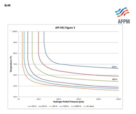
High temperature hydrogen attack damage is cumulative, not instantaneous, and is difficult to detect on inspection until it reaches the latter stages of damage. UOP has conducted a series of surveys and investigations on incidents from various customers. We have found that during a loss of feed case, for example, REACs cool down to temperatures below the killed carbon steel curve within about an hour. We also estimated that over the life of the unit, there would never be more than, let’s say, a wild number 400 of these incidents, which led us to use the 400-hour incubation curve from Figure 3 of API 941, shown here. The green line in the center is the 400-hour curve.
Regarding runaway temperature reactions in the reactor, by the time the excursion reaches the REAC, both the temperature and the pressure should be much lower than when the incident initiated. Temperatures should not be a major threat as long as the temperature runaway incidents do not occur on a regular basis. If the unit experiences frequent temperature runaways, we recommend a Fitness for Service evaluation.
From a physical perspective, Paul already discussed the potential for thermal stress. As hotter than normal temperatures enter the REAC, the first-pass tubes will be heated up quickly; the other tubes will heat up more slowly. Consequently, the first-pass tubes will thermally expand more than the second-pass tubes. This thermal stress can result in bowing of the tubes; and in extreme cases, tubes may pull out of tube sheet. It is assumed that operational temperature excursions are considered in selection of fins for the REAC so that the fins remain firmly attached to the tubes in spite of high temperatures.
One last point: If the reactor effluent air cooler uses induced draft fans, the potentially higher temperatures need to be used to evaluate the materials of construction. For example, fiberglass fan blades may not be acceptable for this application.
Year
2015
Process
Question 48: What is your experience bringing hydrocracking catalyst online without ammonia attenuation? Are there alternative methods or technologies to temper catalyst activity without adding ammonia?
MORELAND (Valero Energy Corporation)
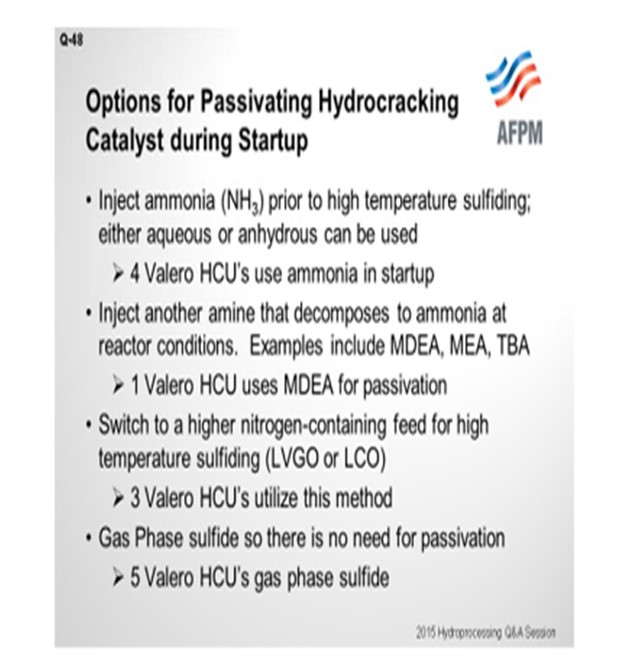
Hydrocracking catalyst needs to be passivated during sulfiding to avoid potential temperature runaway as temperatures are increased to complete the sulfiding process. In our experience, there are four different ways that we attenuate the catalyst activity. The first is to inject ammonia prior to the high temperature sulfiding to passivate the catalyst. We have used both aqueous and anhydrous ammonia for this passivation. Four of our hydrocrackers utilize this method.
The second method is to inject another amine that decomposes to ammonia at reactor conditions. For examples, we have used MDEA (methyl diethanolamine), MEA (monoethanolamine), or TBA (tri-n-buytlamine). One of our hydrocrackers recently used MDEA for hydrocracker catalyst passivation.
The third method is to switch to a higher nitrogen-containing feed for the high temperature sulfiding stage. Three of our units use this method, though we will caution you to be extra careful with passivation via this method and follow procedures. Several cases where we have had temperature excursions on startup have occurred when we were trying to utilize high nitrogen feed for passivation and either procedures were not followed or temperature ramps were faster than anticipated.
Then finally, gas-phase sulfiding: There is no need for passivation if there is no hydrocarbon in the system. Just using hydrogen and H2S can sulfide the catalyst without risk of runaway. Five of our units use that method. I will show you a couple of pros and cons.
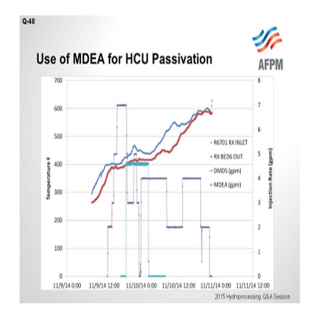
The next slide shows one example of using an amine for sulfiding. It is probably the most uncommon for those of you in the audience. You can see that the red and blue lines are the reactor temperature profiles. The blue is the inlet; the red is the outlet. The purple is the DMDS (dimethyl disulfide) injection rate on the right axis. The light blue color is the MDEA injection. As we heat up to the low-temperature sulfiding temperature and begin DMDS injection, we start the low-temperature sulfiding step. We heat up to about a 425°F inlet here, and then we inject the MDEA during the low-temperature sulfiding, once sulfur uptake is established, to build up the ammonia into the system. The ammonia generated from amine decomposition passivates the catalyst. We then can start the temperature ramp-up to the finishing temperature of around 600°F for the sulfiding. You can see from the dates that this catalyst activation was fairly recently conducted.
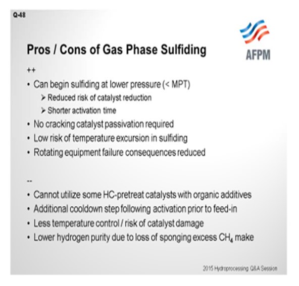
Finally, I want to cover the pros and cons of gas-phase sulfiding because we do use this in five of our hydrocrackers. On the pro side, we can begin sulfiding at a lower pressure: less than the minimum pressurization temperature. Many of our units have limited capability to pressure-up to normal operating pressure and are limited to 100 to 200 psi per-hour ramp rates. Therefore, pressuring up to 2000 pounds can take a significant length of time. So, there is time savings to be able to sulfide catalyst as you are coming up in pressure, as well as reduced risk of catalyst reduction if there is not sulfur in the system yet. The risk of reducing catalyst is greater at higher reactor hydrogen pressures.
No cracking catalyst passivation is required, which I already mentioned. There is less risk or almost no risk of temperature excursion during sulfiding, at least in terms of a runaway based on hydrocarbon cracking chemistry. And then, rotating equipment failure consequences are reduced, particularly the loss of a charge pump during sulfiding. You do not have any liquids circulating.
The downsides of gas phase sulfiding: There is some hydrocracker pretreat catalyst with certain additives that are not able to be gas-phase sulfided to preserve activity. I think Scott referred to that earlier. There is also an additional cooldown step required prior to feed-in, so some of the time savings we get in the earlier step are reversed because we have to cool back down to, say, 300 to 350°F before we put in oil. Additionally, there is less temperature control in gas-phase sulfiding, so temperature can go up, particularly just due to the exotherm from the sulfiding itself or from an absorption exotherm from the first time you put in oil. There is also a lower hydrogen purity due to the loss of sponging excess methane make from DMDS decomposition. So those are some of the cons of gas-phase sulfiding.
PEDERSEN (UOP LLC, A Honeywell Company)
Andy, you did a really good job going through all of those various scenarios. I would suggest, however, that even with liquid-phase sulfiding, ammonia passivation is not absolutely necessary. Lower activity hydrocracking catalysts can be safely started up without ammonia passivation, although careful compliance with startup procedures is necessary. Certainly, during the gas-phase sulfiding step, there is minimal risk for temperature runaway. Many units that have completed gas-phase sulfiding have also used ammonia passivation of the cracking catalyst to facilitate ramp-up of temperatures after oil introduction, particularly units that are heat-balance-constrained and which require aggressive ramping of cracking temperatures in order to bootstrap up the reactor inlet temperatures.
Ammonia is a very effective acid site inhibitor. The other advantage of ammonia is that it is very easily removed from the catalyst surface when it is time to push the conversion. Andy mentioned the use of aqueous ammonia. There has been a lot of success with the application of aqueous ammonia, as well as anhydrous. He also mentioned a variety of chemical additives that can be used to produce ammonia artificially.
The issue with chemical additives is that, to a large extent, they are not very efficient. The nitrogen content is relatively low. Many of these additives have some toxic characteristics that constrain the operator with regard to handling, and some of the popular amines are quite expensive. So it can get very costly to take this approach. For example, with TBA, there is only 7% nitrogen in the composition, which only produces 9% on weight of ammonia for the amount of TBA injected. Quite a line of trucks can be required to complete ammoniation of cracking catalyst in a big unit.
MORELAND (Valero Energy Corporation)
That is right.
PEDERSEN (UOP LLC, A Honeywell Company)
Andy mentioned the use of MDEA to generate ammonia, which is, as he indicated, a relatively recent development in the industry. I want to note that even with MDEA, the nitrogen content is less than 12%. And more importantly, for every mol of ammonia produced, two mols of water are generated. So consequently, injecting MDEA produces just as much water as injecting the most popular form of aqueous ammonia, which is 30% ammonia solution. I want to mention that there is also now a technology available to inhibit hydrocracking catalyst acid activity offsite prior to catalyst loading. This approach has been applied successfully in a couple of instances.
MORELAND (Valero Energy Corporation)
I meant to mention that one of the reasons we use MDEA is because that chemical was already approved in our plant at the time, which can make turnaround planning a little more straightforward. It is also not that expensive.
PEDERSEN (UOP LLC, A Honeywell Company)
No, not that one. [Laughter]
TEMME (Albemarle Corporation)
Andy and Mike covered the question comprehensively, so I have nothing further to add.
DAVID GATES (Motiva Enterprises LLC)
I want to comment on the use of ammonia passivation and say that I believe most folks are strongly recommending the use of aqueous ammonia as opposed to anhydrous ammonia due to safety concerns. So certainly, if you are going to use anhydrous ammonia, make sure you are taking proper safety precautions.
TEMME (Albemarle Corporation) Yes. Absolutely.
JAMES (TIM) CAMPBELL (Eurecat U.S. Corporation)
I want to add onto Mike’s last comment. Eurecat’s process is called HCAP. HC means the hydrocracking catalyst is fully activated; AP is acidity protection. Basically, it eliminates the need for ammonia, amines, and high nitrogen feed. It is a lot faster, at least 50% faster, than a gas-phase startup.
VIJAY SRINIVAS (Arkema Inc.)
I want to mention that we have a new amine which contains about 26% active ammonia and decomposes at low enough temperatures.
UNIDENTIFIED SPEAKER Bring in some energy. Is there a bar over there?
ROBERTSON (AFPM)
He is turning into Warren Letzsch before our eyes. [Laughter]
M. SCOTT GREEN (KP Engineering, LP)
I have a question for the panel. On the gas-phase sulfiding option, do you experience any problems with, say, pocketing of the water that is generated from the sulfiding? I know that in some units, such as naphtha hydrotreaters, where you have gas-phase sulfiding startup, the units sometimes have pockets that are not issues during normal operation but which can be on this step. Getting rid of that sour water while you are doing your activation is a lot harder than, say, on a liquid-phase sulfiding startup. The units designed for liquid-phase sulfiding are designed to push the water generated to the separator boots and get rid of the water automatically. So, do you have any issues with that on the gas-phase sulfiding startup option on the hydrocrackers designed for liquid-phase sulfiding?
MORELAND (Valero Energy Corporation)
In our procedures, we must make sure those sour water boots are lined up and that the water will go the same place. But often, we do not have oil-in. Operations may have them all blocked in. The next thing you know, you are filling the separator with water. So it is a good consideration in gas-phase sulfiding.
RANDY ALEXANDER (Reactor Resources LLC) I want to point out that Reactor Resources pushed for the use of MDEA and completed one of the first jobs with it. The idea was safety. MDEA has a safety health hazard rating of 1; ammonia has a rating of 3. So it is just a safer method of injecting nitrogen into the system and getting away from ammonia, which can be hazardous. Tributylamine (TBA) also has a hazard rating of 3. The advantage of TBA is that it does not form water when it decomposes. So it is used in some special cases where water is an issue.
DAVID VANNAUKER (Haldor Topsoe, Inc.) Haldor Topsoe, Inc. has tested a variety of different startup procedures in their pilot plants and has performed more than 50 HDC commercial unit startups without the use of ammoniation. Understanding the feed, operating conditions, and the zeolite can lead to a significant savings in expenses by avoiding the cost of ammoniation facilities and an improvement in profitability by reducing line-out time and getting the products to finished tankage. On-specification production improvements have ranged from a shift to a couple days. The Topsoe startup procedure without the use of ammonia is also a very safe startup minimizing the runaway concerns. For a hydrocracking unit, this is extremely valuable.
JOE FLORES (Criterion Catalysts & Technologies / Zeolyst International)
From an activation standpoint with hydrocracking catalyst, it is always easier to gas-phase sulfide rather than liquid-phase sulfide. An advantage with gas-phase sulfiding is the ability to start sulfiding at lower pressures without having to wait for MPT (minimum pressurizing temperature) to be reached. In addition, since there is no liquid present, the need for passivation of the hydrocracking catalyst is not required. Liquid-phase sulfiding will add potential issues due to dealing with ammonia injection; i.e., pump and safe handling issues. There are also several necessary precautions to prevent cracking of the oil when raising temperature to complete liquid-phase sulfiding activation of hydrocracking catalysts.
Premature cracking of the oil can result in coke laydown and/or a temperature excursion, leading to loss of activity or even a possible loss of containment.
An additional complication of liquid-phase sulfiding is that many unit charge pumps cannot operate at low pressure, so the sulfiding must be conducted at higher pressure. Sulfiding at high pressure in the presence of hydrogen, before H2S breakthrough, can lead to metals reduction on the catalyst, resulting in loss of catalyst activity.
The hydrocracking catalyst needs to be passivated. Methods of passivating the catalyst include using anhydrous or aqueous ammonia injection, amines, or an appropriate straight-run gas oil containing high concentrations of nitrogen.
Liquid-phase sulfiding introduces additional complications and variables to control, and a failure of a piece of equipment during the sulfiding can lead to an undesired outcome. When performed according to recommended guidelines, either liquid or gas-phase sulfiding will give similar activity.
Year
2015
Process
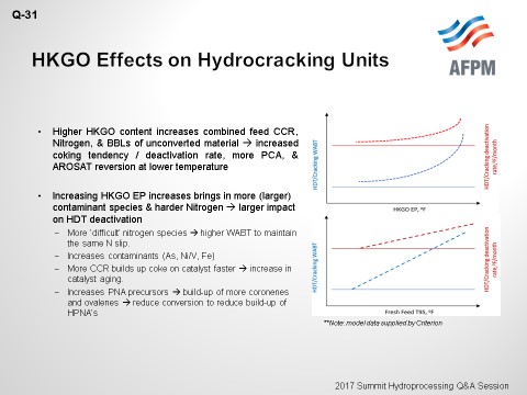
Question 31: What are the potential impacts to hydrocracking units [i.e., deactivation rate, HPNA (heavy polynuclear aromatics) formation, etc.] as heavy coker gasoil (HCGO) rate/endpoint are increased?
JOHNSON (Motiva Enterprises LLC)
What we have modeled here for you today is both cases. So, obviously, in a general sense, increasing heavy coker gasoil content will increase Conradson carbon and nitrogen. Then, the coking tendency in deactivation rate will also increase.
To walk you through the curves, the top case shows when we are looking at the treating and cracking reactors relative to increasing the endpoint only. As you can see, in the beginning, the curve is fairly ‘flat’, in terms of the deactivation rate. However, depending on the ‘severity’ of the endpoint shift, you will get more of an exponential curve increase in deactivation. In the other case where we hold cutpoint constant and increase the percentage of heavy coker gasoil within the feed pool, we get more of the linear relationship, in terms of deactivation rate on cracking and treating reactors.
Obviously, the more ‘difficult’ nitrogen species will increase contaminants such as nickel, vanadium, and arsenic, which will also cause more carbon buildup on the catalyst and increase catalyst plugging and aging. With heavy coker being as olefinic as it is, we are also increasing the polynuclear aromatic precursors and then, therefore, increasing the buildup of our polynuclear aromatics. It is interesting to see what truly happens at cutpoint versus just barrels on qualities.
RAMACHANDRAN (Bharat Petroleum Corporation Limited)
From a practical standpoint, the impact of higher feed rate and endpoint increases
-
Fouling of heat exchangers,
-
Plugging of high-pressure vapor coolers,
-
Pressure drop on the catalyst bed,
-
Deactivation of catalyst, and
-
The formation of coke, and also causes coloration and instability in the product.
The impacts of this higher feed rate and end point can be reduced by ensuring that we have an amount of drag or purge stream – sometimes at the cost of conversion – which will split unconverted oil into light and heavy fractions. Only the light stream is recycled; the heavier stream is taken away as rejects. What helps is selective HPNA absorption from the recycled stream, as well as maintaining the feed endpoint typically around 1022°F instead of 1100+°F in case of once-through hydrocrackers with about 85 to 90% conversion. Maintaining a high recycle ratio in the coker also helps, although it will result in more coke formation and will crack into lighters at the cost of distillates.
PAPPAL (Valero)
In an extinction recycle hydrocracker with high conversion targets, HPNA (heavy polynuclear aromatics) production likely increases as CHGO is added to the feed. Generally, you have to reduce conversion and increase unconverted oil purge rate to compensate for the increased HPNA production. To judge the viability of CHGO upgrading through an extinction recycle hydrocracker, an economic analysis is likely required. The overall value of processing CHGO through the hydrocracker would be compared to the next best non-hydrocracking alternative for processing the CHGO. In general, the higher the pressure of the hydrocracker, the more improved the capability for upgrading CHGO at high conversion levels will be.
SALVATORE TORRISI (Criterion Catalysts & Technologies, L.P.)
I have a response and a question. In general, my experience is that coker fractionators perform differently than vacuum towers. A10ºF increase in endpoint for a coker gasoil adds more difficult species than when you increase HVGO endpoint by 10°F. The actual fractionation quality is not quite as good in a coker, so that seems to drag in a lot or all of the elements you mentioned.
I heard you speak about many of the impurity implications except for asphaltenes. Do you have any general rules for asphaltenes, in terms of increasing endpoint by 10ºF? Is there a maximum value you recommend for color, asphaltene content, or metals level, from a coker feed quality standpoint? Do any of the panelists have an opinion? When is an endpoint too high?
PAPPAL (Valero)
CHGO in a properly functioning unit should be very low in asphaltene content. A typical number quoted is 300 to 500 ppm as the limit of asphaltene content to a hydrocracker. So, if a blended feed starts exceeding that value, deactivation will likely increase. Online measurement of HPNA in unconverted oil is currently unavailable. What is needed, from an operating standpoint, is a quick-and-dirty workaround that relates the laboratory-measured HPNA values with an easily measured property. An example is using the color of the UCO as a proxy for the HPNA content of that stream. The objective is to limit the HPNA within targeted levels. As more difficult feed is added to the hydrocracker, optimization within limits is required.
JOHNSON (Motiva Enterprises LLC)
In terms of Motiva’s experience with processing heavy coker gasoil, typical limitations you are up against are the coke fines themselves, especially if we have drum switching issues, just like David was saying with the color as a ‘go-by’ and not directly measuring the PNAs. However, the color is an indicative point of where you stand, in terms of how much higher you can push conversion. We have never had an experience when we were able to maintain conversion targets in the 96 to 98% range. But when pushing the percentage of the pool, we do start to see some color changes and other limitations on filtration and pressure drops.
HEIDI DALEY (Haldor Topsoe, Inc.)
HCGO will contain very high nitrogen content and can also have high concentration of polyaromatics and carbon residue as the endpoint is increased. Higher HCGO rate and/or endpoint will, therefore, increase the catalyst deactivation rate in a hydrocracker. Obviously, from a catalyst vendor’s perspective, we recommend that you utilize a catalyst with maximum HDN (hydrodenitrification) activity in this application to deal with the higher nitrogen feedstocks. In addition, a tailored guard bed will help to minimize contamination of those high-activity catalysts that are designed specifically for some of the contaminants that will be present.
For a full conversion unit with recycle, HPNA formation will increase as you increase the endpoint and/or the amount of coker gasoil in the feedstock. HPNAs will have to be managed to avoid buildup in the recycle oil. Haldor Topsoe’s solution is our HPNA Trim™ technology which can be added to an existing hydrocracking unit. It basically involves removing the HPNAs with a simple stripping operation added to the backend on the recycle oil – as was mentioned previously – and separating HPNAs out based on their higher boiling point, thereby greatly reducing the likelihood of deactivation of the catalyst due to the condensation of the heavy PNAs.
ANDREW MORELAND (Valero)
Waterwash is another limit you will hit. A lot of our units cannot handle increasing heavy coker gasoil or any increase in feed nitrogen content based on waterwash limitations.
RAJESH SIVADASAN and SIMERJEET SINGH (Honeywell UOP)
Processing heavier and cracked feedstocks poses many challenges to the hydrocracking unit. Thermally-cracked feedstock such as HCGO, apart from being unsaturated, has relatively lower API, higher sulfur, and nitrogen content, higher proportion of C7 insoluble, and Conradson carbon residue (CCR). An increase in the HCGO distillation endpoint results in a significant increase in the proportion of polynuclear aromatics (PNA) and asphaltenes, both of which are coke precursors, which results in an exponential increase in catalyst deactivation rates.
Analysis of a commercial HCGO feed sample indicates that the proportion of 4- to 5-ring aromatic compounds, which are HPNA precursors, begins to appear in the feed as the HCGO 95% distillation point approaches 775°F (410°C) and increases exponentially with each incremental step change. Figure 1 below shows a typical change in HCGO feed PNA concentration with the increase in the tail-end distillation.
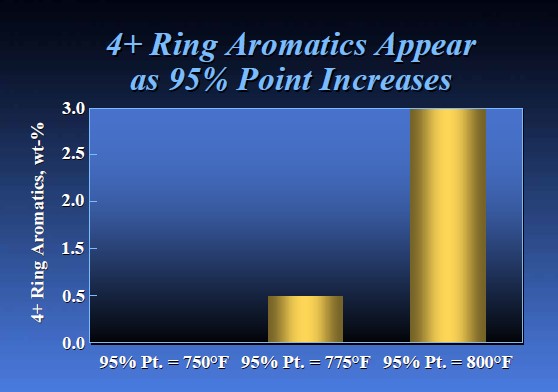
Figure 1.4+-Ring Aromatics
Figure 2 below shows four different feed streams with their PNA type breakup. Red dots are the distillation endpoint of each of the feed blend components. It can be seen that even though the HCGO endpoint is much lower than the SR VGO, relative concentration of 5- and 7-ring+ compounds or PNA precursors is much higher. Increased proportion of these precursors in the feed may result in HPNA buildup in the unit for the same conversion.
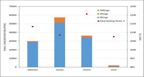
Figure 2.PNA-Type Breakup
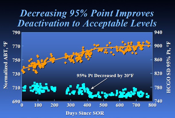
Figure 3. Increased HCGO Endpoint
Increased quantities of HCGO processing also increases the pounds of silica entering into the unit. If the guard bed catalyst does not have sufficient margin to remove this silica from the feed, it may lead to premature breakthrough into the main treating catalyst leading to shortened life; so, the guard bed catalyst also needs to be customized for processing HCGO in the unit.
Other issues with HCGO processing in a hydrocracker unit is the inability to or difficulty in maintaining the design HCGO endpoint due to transient nature of delayed coker unit operation. Increasing the sampling frequency, Advanced Process Control implementation on coker fractionator, and use of SIMDIST test methods D2887/D7169 (instead of D1160) often prove useful in monitoring and controlling the quality of HCGO feed. Advanced characterization methods like high-resolution mass spectroscopy (HRMS) can be also be utilized, especially during the design stage, to identify the feed contaminants at the molecular level and customize the catalyst system and unit design.
Both new and existing units with the capability of processing these types of feeds should have high operating pressure (preferable greater than 2,000 psi), larger reactor volume, and sufficient capacity margin in the existing hydrogen supply to cater to the increased demand. Depending on the unit operating severity, recycle gas scrubber, hot separator, and some sort of HPNA management option may also need to be included in the unit process flow scheme to improve the unit’s reliability and maintain or exceed the existing catalyst cycle lengths.
RICHARD TODD (Norton Engineering Consultants, Inc.)
Heavier feeds will definitely have an impact on both the pretreating catalyst and the cracking catalyst. Pretreat deactivation may increase significantly and affect cycle life. The potential of fouling exchanger surfaces also increases due to HPNA formation, which may also limit cycle lengths. In an HC without recycle or with the bottoms going to an FCC, catalyst aging may be the primary effect.
Year
2017
Process
Question 32: A) What are the variations of target efficiency that can be achieved in hydrogen plant operation? B) What are the operational factors that impact efficiency?
LONG (HollyFrontier Corp - Navajo)
Hydrogen plants have several areas to target, when it comes to efficiency. There are several factors that contribute to energy efficiency, and all process variables vary greatly from plant to plant.
I am going to start with the pressure swing absorber. The main target production efficiency of a hydrogen plant is the PSA (pressure swing adsorber) efficiency. This is calculated as a ratio of PSA product hydrogen to inlet PSA hydrogen. A PSA efficiency greater than 85% is considered to be adequate. Another ratio to consider is efficiency of conversion, which is the unit feedstock- to-hydrogen production ratio. This efficiency of conversion has an impact on total plant operations. Typical efficiency of conversion is 2.1 to 2.4, and variations in the plant average value can indicate operational upset. Operational impacts on PSA efficiency consist of valve switching failures and PSA feed gas. As carbon monoxide concentrations increase in feed gas, the efficiency of the PSA is reduced. Another way to measure energy efficiency is by evaluating the energy conserved per unit of hydrogen produced.
Now we move on to the reformer. The factors that can impact energy efficiency in a steam methane reformer (SMR) indicate catalyst activity, burner operations, heat lost to atmosphere, furnace operation, heating values in BTU (British thermal unit), tube life, shift equilibrium or steam-to-carbon ratio S/C, and potentially ambient temperature. A direct-monitored target for SMR consists of methane slip and outlet target temperature, which varies from plant to plant. Methane slip consists of 1.5 to 5 dry mol% and impacts heating values, in terms of BTU. Methane slip is controlled in the reformer by shifting the equilibrium or manipulating the steam-to-carbon ratio and SMR outlet temperature. Typical steam-to-carbon ratio is 2 to 3.5, but this ratio can greatly vary; again, from plant to plant.
If the reformer reaction equilibrium was shifted to increase hydrogen make, steam, or temperature, this modification will reduce methane content in the PSA off-gas in the reformer heater. As BTU values of the off-gas decrease, the secondary burners may have to be fired harder, which will require an increased amount of purchased natural gas. Increasing methane slip correlates to an increase of heating efficiency and – potentially – an increase of reformer tube life. Increasing methane slip is achieved by decreasing the steam-to-carbon ratio or decreasing reformer outlet temperature. To increase hydrogen, make, the steam-to-carbon ratio can be increased; however, impacts, heating value, and tube life should be considered. It should also be noted that operating at higher reformer temperatures will directly decrease tube life and catalyst life.
In the high-temperature shift converter, the factors that impact energy efficiency in the shift converter are the inlet temperature and catalyst activity. The shift converter should target constant inlet temperatures as temperature swings impact catalyst activity.
The exotherm across the shift converter should be monitored, as well as CO slip. Inlet temperature can be increased to maintain constant exotherm as catalyst deactivates. The local startup temperature differential is 100ºF, and a target startup run temperature is below normal. It is common to have temperature step changes that occur every six months. If a plant is short on hydrogen, the inlet temperature can be increased to promote CO conversion. The target shift converter CO slip consists of 1.5 to 3 dry mol% and indicates catalyst deactivation. This percentage depends on each facility, as well as start-of-run conditions. The operational factors that impact efficiency of carbon monoxide slip are inlet temperature and the steam-to-carbon ratio. CO slip can be decreased by increasing inlet temperature or increasing the steam-to-carbon ratio. The temperature differentials will be indicated by catalyst activity. Inlet temperature can also be increased to achieve the target temperature differential, which changes from plant to plant.
Lastly, the sulfur guard: Frontend sulfur removal has an impact on catalyst efficiency in the hydrogen plant. The sulfur component being removed is H2S (hydrogen sulfide) and variations of mercaptans. The desulfurization previously consisted of activated carbon at ambient temperatures. Desulfurizers have used several types of media, from zinc oxide to carbon beds. The media type can impact efficiency, depending on the plant design and temperature parameters.
AGGUS (Becht Engineering Co., Inc.)
All I will add about efficiency is that a lot of the people who designed the plant – CB&I, in particular – use a plant efficiency term. It is not just the amount of natural gas you convert to hydrogen; you have to throw the steam in there as well. I do not know how many hydrogen plant unit engineers we have here. But to those who are in the audience, I want to say that it is a good exercise to add this efficiency calculation to your daily monitoring. You want to take the amount of feed on a heating value basis, the fuel that is going into the furnace, and then the difference between your energy and boiler feed water to steam, and then divide that by the hydrogen product. If you monitor those values every day, you will be doing a good job of taking care of your SMR. If only it was that simple, right?
The heavy hitter, as far as energy usage and efficiency in your SMR, is the furnace. It is just like any furnace: You want to be able to monitor your excess oxygen and excess air. So, try to maintain 2.5 to 3% excess O2 in the furnace. What also really affects the efficiency of hydrogen recovery, as Sarah said, is the PSA. The unit temperature is easy to monitor. Make sure you are staying below 110ºF. It is your PSA. You will have best absorption efficiency if you do that. Then if you are really nice to your process control engineers, you can also play with the cycle time on the PSA. So, longer absorption times will give you less hydrogen loss and blowdown repressurization and should increase your recovery.
LEWIS LUDWIG (UNICAT Catalyst Technologies, Inc.)
I will just say that the typical minimum for steam-to-carbon ratio is 2.8. I think the panelist said 2. We think you would run into real problems running at 2. The other important point is pressure: the lower the pressure you can run on the outlet of the SMR, the better the equilibrium. However, that is usually a design consideration and not something that the operator can do with an existing SMR.
KEN CHLAPIK (Johnson Matthey)
I have a few comments. One, in tomorrow’s P&P session, we will have Air Products talk to us about some of their experiences in dealing with efficiency through the decades that they have been producing hydrogen. It will be an operator’s view, so you are welcome to experience that at 8:00 tomorrow morning.
We put a lengthy answer in the Answer Book, and I want to add two comments about efficiency now. We are hearing that a lot more hydrogen plant operators want to address and improve on efficiency. As you start to change some of these variables, monitoring your unit will become even more important. The steam methane reformer, as has been said by the panelists, is a critical part of that hydrogen production unit. We have been working with Daily Thermetrics over the last decade and have developed and established the application of their CatTracker® thermometry for in-tube reformer thermometry. CatTracker® for reformers gives you a “sight glass” in that reformer, with respect to the reactions that are going on in the tube. When running the reformer at these more efficient conditions, the operator can see the quick response of operating changes as they are made. This enables the operator to maintain reliability at these new conditions, which is so important in hydrogen production.
My other comment is that there are operators who are trying to look at low capital ways to address efficiency and production. Usually when you start looking at improving efficiency at low capital, this limits the number of options. Johnson Matthey has a step out reforming technology in our CATACELJMSSR, a stackable structure reactor that replaces the catalyst pellets in the reformer tube. SSR enables an operator to make a step change in efficiency through improved heat transfer, activity, and pressure drop in the reformer tube allowing the same production with 5 to 10% less firing or 5 to 10% more production prior to plant modifications.
ROBERTSON (AFPM)
Since there are no other questions, we will now conclude this Question & Answer session. Thank you, again, to all of the panelists for their informative presentations and responses today. We appreciate all of their efforts and contributions. And, thanks to all of you here today for your participation, as well.
BRANT AGGUS (Becht Engineering)
When discussing efficiencies, it is important to define the plant efficiency term. In most cases, hydrogen plant efficiency is measured by calculating the energy [BTU/scf (British thermal unit/standard cubic foot)] required to generate product hydrogen. This calculation involves adding input streams on an energy basis (feed and fuel), subtracting the output streams (export steam, other export streams, etc.), and then dividing the result by the product hydrogen flow (see equation below).
Efficiency (BTU/scf) LHV: (Feed + Fuel – Steam)/Hydrogen Product
The export steam term is based on the energy difference between the export steam conditions and the incoming boiler feedwater conditions. This simple formula is used by technology licensors, like CB&I, to benchmark unit performance. It is a good idea to include it in daily unit monitoring and long-term trending.
Plant configuration, particularly the addition of combustion air preheat, will affect efficiency; so, it is important to compare like-to-like.
In addition to the items Sarah covered about operational factors that impact efficiency, I will add that furnace-side operation has a large impact on overall plant efficiency. Excess air should be minimized (typically to 10%, or 3% excess O2).
For the PSA unit, the cycle time can be maximized to decrease the hydrogen loss associated with the blowdown and repressurization steps. In addition, the inlet temperature should be maintained below 110°F for optimal performance of the unit.
SARAH LONG (HollyFrontier Corp - Navajo)
Hydrogen plants have several areas to target when it comes to efficiency. There are several factors that contribute to energy efficiency, and all process variables vary greatly from plant to plant.
Pressure Swing Adsorber (PSA)
The main target production efficiency of a hydrogen plant is the PSA efficiency. PSA efficiency is calculated as a ratio of PSA product hydrogen to inlet PSA hydrogen. A PSA efficiency greater than 85% is considered to be adequate. Another ratio to consider is efficiency of conversion, which is the unit feedstock-to-hydrogen production ratio. The efficiency of conversion has an impact on total plant operations. Typical efficiency of conversion is from 2.1 to 2.4, and variations in the plant average value can indicate operational upset. Operational impacts on PSA efficiency consists of valve switching failures and PSA feed gas. As carbon monoxide (CO) concentrations increase in the feed gas, the PSA efficiency reduces.
Another way to measure energy efficiency is by evaluating the energy consumed per unit of hydrogen produced.
Reformer
The factors that impact energy efficiency in the steam methane reformer (SMR) include catalyst activity, burner operation, heat loss to atmosphere, furnace operation, heating values (BTU), tube life, shift equilibrium or steam-to-carbon ratio (S-C), and potentially ambient temperatures. A direct monitoring target for the SMR consists of methane slip and outlet temperature, which vary from plant to plant. Methane slip consists of 1.5 to 5 mol% dry and impacts heating values, in terms of BTU. Methane slip is controlled in the reformer by shifting the equilibrium or by manipulating S-C and SMR outlet temperature. Typical S-C is 2 to 3.5, but it can greatly vary from plant to plant.
If reformer reaction equilibrium was shifted to increase hydrogen make, the result will also be in a reduction in methane content in the reformer heater PSA off gas. As BTU value of off gas decreases, the secondary burners may have to be fired harder. This shift to increase hydrogen make requires an increased amount of purchased natural gas. Increasing methane slip correlates to an increase of heating efficiency and potentially an increase of reformer tube life. Increasing methane slip is achieved by decreasing S-C ratio or decreasing reformer outlet temperature (temperature is in range). To increase hydrogen, make, S-C can be increased, but increasing hydrogen can have an impact on heating values and tube life should be considered. It should be noted that operating at higher reformer temperatures directionally decreases tube life and catalyst life.
High-Temperature Shift Converter (HTSC)
The factors that impact energy efficiency in the shift converter are the inlet temperature and catalyst activity. Shift converters should target constant inlet temperatures as temperature swings impact catalyst activity. The exotherm across the shift converter should be monitored, as well as the CO slip. Inlet temperature can be increased to maintain a constant exotherm as catalyst deactivates. The local startup dT (delta T; temperature differential) is 100°F, and a target SOR (start-of-run) temperature is below normal. It is common to have temperature step changes occur every six months. If the plant is short on H2, the inlet temperature can be increased to promote CO conversion. The target shift converter CO slip consists of 1.5 to 3 dry mol% and indicates catalyst deactivation. These process conditions depend on each facility and on SOR conditions. The operational factors that impact this efficiency or CO slip are inlet temperature and S-C ratio. CO slip can be decreased by increasing inlet temperature or increasing S-C ratio. The temperature differentials will indicate catalyst activity. Inlet temperature can also be increased to achieve the target temperature differential, which changes from plant to plant.
Sulfur Guard
Front-end sulfur removal has an impact on catalyst efficiency in the hydrogen plants. The sulfur component being removed is H2S and variations of mercaptans. The desulfurizers previously consisted of activated carbon beds at ambient temperatures. Desulfurizers have used several types of media from zinc oxide to carbon beds. The media type can impact efficiency depending on plant design and temperature parameters. Desulfurizers have gone into the direction of a variation of zinc oxide catalyst. Zinc oxide catalyst can increase carbonyl sulfide removal, along with increase efficiency by decreasing heat requirements, with regard to CSO. To increase sulfur removal efficiency, a layer of HDS catalyst can provide increased removal of organic sulfur compounds.
ABIGAIL SUP (Johnson Matthey Inc.)
Part A: Modern hydrogen plants are around 5 to10% more efficient than those built in the 1990s. These improvements have been achieved through flowsheet modifications such as pre- and post-reforming [for example, a GHR (gas-heated reformer), MTS (medium-temperature shift), pressure swing absorption (PSA), and the use of combustion air preheat, as well as advancements in catalyst technology (e.g., Johnson Matthey’s CATACEL SSR). Modern flowsheets can be very efficient with estimates approaching the theoretical minimum amount of energy required to produce a unit of hydrogen with values of just over 300 BTU/scf of hydrogen (taking credit for steam export) being quoted for some plants. Though for typical hydrogen plants in operation today, energy efficiency values generally are in the range of 350 to 425 BTU/scf of hydrogen.
The thermal efficiency of a hydrogen plant will depend on the:
-
Quantity of heat recovered from the process gas.
-
Amount of heat recovered from the flue gas.
-
Total heat loss to the environment (function of size, design, condition of reformer).
-
CH4 (methane) slip from the reforming section (impacted by steam-to-carbon (S-C) ratio, catalyst selection and age, reformer balancing, reformer design, material limitations, etc.).
-
CO slip from the WGS (wet gas scrubber section) (catalyst selection and age, configuration: HTS, MTS, HTS+LTS, WHB size); and/or,
-
Downstream purification design (PSA versus CO2 removal/methanation, PSA efficiency).
For new plant designs, improvements in energy efficiency are generally evaluated against any increases in capex (capital expense) and/or opex (operating expense) required. For example, an MTS flowsheet may achieve a lower CO slip compared to an HTS, but the value of the additional hydrogen may not be able to off-set the additional capex required, such as the cost of a larger waste heat boiler (WHB), a more expensive catalyst, larger catalyst volumes, greater susceptibility to poisoning, and a reduction system.
The optimal plant efficiency for any plant will vary due to factors such as the:
-
Cost of feed,
-
Cost of fuel,
-
Cost of power, and
-
Value of steam.
There are also numerous other factors that impact plant design, which then affect the efficiency of the plant. Some of these factors include plant scale, feedstock flexibility, turnaround schedule, payback targets, compression requirements, pressure drop versus vessel cost.
Part B: A hydrogen plant is designed with a specified arrangement for heat integration which sets the theoretical limit for the plant’s efficiency. The operational factors that provide the largest impact in moving a plant towards this limit include the following:
-
Plant rate: Generally, the plant is less efficient at lower rates due to the relatively higher heat losses and difficulty in maintaining good distribution, which can result in a higher CH4 slip or require a higher S-C.
-
Reformer balance: maintenance of burners, adjustment of air dampers and fuel pressure, condition of tunnels, etc.
-
Ability to properly identify and measure plant bottlenecks; e.g., accuracy of tubewall temperatures (TWTs), sampling analysis, instrumentation, etc.
-
Determining the optimum steam-to-carbon ratio: reducing steam requirement without compromising catalyst life/performance.
-
Minimizing excess oxygen: decreasing fuel usage while still maintaining reliable operation.
-
Optimization of inlet temperatures to the HTS/MTS/LTS bed for minimum CO slip.
-
Monitoring of purification section to prevent poisoning of downstream units, which can significantly impair the ability to run at optimal operating conditions.
-
Startup and shutdown procedures, which can affect catalyst life and performance.
-
Heat loss: refractory condition, insulation, wind shield, etc.
-
Catalyst selection, which affects CH4 slip over life of charge, heat transfer, pressure drop, carbon formation, etc.
-
Routine cleaning and maintenance of heat exchangers.
When pursuing improvements in energy efficiency, it is important to consider the impact of any proposed changes to ensure continued safe and reliable operation. For example, reducing the steam-to-carbon ratio too far could result in carbon formation on the reforming catalyst or over-reduction of the HTS catalyst. This change to the process could adversely impact the plant’s long-term efficiency or its ability to achieve maximum rates prior to the next scheduled changeout.
For this reason, daily plant monitoring becomes more critical when pushing a plant towards optimal efficiency because the plant is most efficient when it is running closer to its limits. To safely and reliably maintain operation at optimal conditions, operators need to be able to respond to any changes or deviations that could move the plant outside of designated limits (e.g., TWTs, carbon forming conditions, minimum excess oxygen, etc.)
One monitoring tool that can help in this area is Daily Thermetric’s CatTracker® technology, which can be placed directly inside a reformer tube with catalyst loaded around it is using Johnson Matthey’s proprietary loading method. CatTrackers® can measure the process gas down the length of the tube, giving operators continuous feedback on the reformer’s condition. This information can enable operators to detect poisoning, carbon formation, or other issues before they significantly affect performance.
As noted in the list above, catalyst selection also provides an opportunity to relieve operational constraints and improve a plant’s efficiency with minimal capital investment. For example, Johnson Matthey’s promoted reforming catalyst, KATALCO 25-4Q, allows operators to run at lower steam-to-carbon ratios – compared to traditional catalysts – without the risk of carbon formation at more severe conditions. Also, Johnson Matthey’s CATACELSSR can provide a step change in performance by lowering fuel usage for the same capacity, decreasing TWTs allowing the plant to run more aggressively, reducing pressure drop across the reformer, and even allowing an increase in capacity, if needed.
When searching for efficiency improvement opportunities, it is recommended to seek input from a catalyst vendor, such as Johnson Matthey. Johnson Matthey has the tools, modelling capabilities, and knowhow to help operators identify improvement opportunities, evaluate their relative impact/benefit, and provide recommendations that enable customers to improve their overall efficiency. This expertise includes onsite reformer surveys and data analysis, as well as kinetic modelling of the unit operations to predict the impact of operational changes. For more capital-intensive improvements, such as looking for step changes in capacity and efficiency, Johnson Matthey conducts revamp studies.
Year
2017
Process
Question 36: What are your primary indicators that a coker furnace spall is complete? What steps do you take to optimize the efficiency of spalling?
GAMBOA-ARIZPE (CITGO Refining & Chemicals, L.P.)
A cautionary foreword: Online spalling of furnace heater tubes is not suitable for every heater design. It is necessary to consult with your furnace licensor or manufacturer to determine if online spalling practices are compatible with the heater designs installed in your respective facilities. There will be a more complete answer in the final transcript, including a more detailed discussion on the practice of delayed coker furnace spalling and the factors used to determine when the decoking operation of the furnace is needed. The verbal answer will only address the descriptive metrics currently being employed to determine when a furnace spall is considered ‘complete’. Technically, however, the primary question here is a difficult one to answer, because the completeness of a spall can only be determined post-spall with the furnace back online and after tube wall temperatures are measured; and to a lesser degree, after the heater pass pressure drop on normal oil flow has also been measured. Fortunately, the completeness of a spall can also be based on previous experience with a particular furnace and can be managed procedurally. That is the basis on which I will attempt to answer this question.
CITGO Petroleum Corporation operates four delayed coker units amongst its three U.S.-based refineries. Three out of the four units incorporate routine spalls for their respective coker furnaces as part of a broader operating strategy to optimize effectiveness of their overall furnace operation. The fourth delayed coker unit relies primarily on ‘piggings’. The benefits of online spalls versus steam/air decokes versus piggings will vary depending on the logistics of a facility, as well as on the heater’s mechanical configuration and its design. The decoking effectiveness of the three methods is also different. All methods, however, fundamentally aim to remove as much of the fouling coke layer that builds up along the interior surface of the furnace tubes as is possible during the operation.
The buildup of coke within coker furnace tubes is intrinsic to the delayed coking process due to the nature of vacuum residue material once it becomes exposed to the relatively high temperatures that are required by the process (greater than 850°F). While the buildup of coke cannot be totally averted, the rate of this buildup can be managed, depending on the heater design and other factors. The thickness of the accumulated coke layer can be generally inferred by monitoring and trending the furnace tube wall temperatures. Higher tube wall temperatures are indicative of thicker coke buildup because the deposited coke layer has lower thermal conductivity than the metal substrate of the furnace tubes. In effect, the coke layer acts as an insulating barrier that restricts the transfer of heat from the fire box into the process stream, which then allows the metal temperature of the tubes to increase.
Over time, the tube wall temperatures increase as the coke layer thickens. The sections of the heater that begin to experience faster coke buildup also shift with time as more and more tubes begin to experience lower heat transfer. This dynamic is caused by the need to keep the target coil outlet temperature (COT) relatively constant to maintain viable C5+ liquid yields and because the total heat flux across the heater [for a fixed surface area and a known dT (delta T; ∆T; temperature differential)] is also relatively constant. In other words, the gradual reduction in heat transfer efficiency across some of the process tubes forces the furnace to be fired at increasingly higher rates. This firing shift increases the localized heat fluxes in other sections of the heater to meet the specific COT that is dictated by the operation.
Removal of the coke layer at some routine maintenance interval improves the furnace’s overall heat transfer efficiency because it eliminates the insulative barrier that prevents the heater from meeting those COT targets at lower firing rates. Because of this dynamic, the tube wall temperatures tend to increase logarithmically over the course of a run until the coke layer is again removed. The run-length of this recurring operation must be optimized to maximize the refinery’s profits while ensuring that the long-term reliability of the equipment is not compromised.
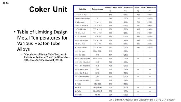
Ultimately, the delayed coker furnace is decoked on an as-needed basis to prevent operation that could produce tube wall temperatures above the limiting design metal temperature of the respective alloy of the furnace tubes [as defined by API 530 (Table 5) or an equivalent table (ANSI, ASME, etc.); see my second slide entitled “Table of Limiting Design Metal Temperatures for Various Heater-Tube Alloys”]. The timing of a decoking operation is, therefore, dictated by the need to manage the reliability of the equipment, particularly to avoid encroaching the mechanical limits of the furnace tubes themselves; especially, long-term operation at the elevated temperatures. Equally important, an alloy’s critical temperature should generally never be exceeded as this could result in changes to the alloy’s microstructure. Note: Per API 530, “Other considerations can require lower operating temperature limits, such as oxidation, graphitization, carburization, and hydrogen attack.”
The API 530 limiting design metal temperature is not necessarily the strict driver for the end-of-run (EOR) tube metal temperature, although one could say it is good practice not to exceed it. The real driver for the EOR temperature is an economic optimization question: If a refiner chooses too high of an EOR temperature, then he or she will have to retube the heater excessively/ often; and if the refiner chooses too low of an EOR temperature, then he will have to decoke excessively/frequently. The short-term mechanical integrity limit for a typical coker furnace tube is appreciably higher than the typical EOR temperature. The tube geometry is a factor as well. For a thick-walled tube, the stresses are lower so higher temperatures can be tolerated. At CITGO, the online spalling operation was introduced as a viable decoking practice as early as 2001, with conceptual preparation going as far back as 1999. The written procedures themselves have been optimized at each respective facility via post-spall performance-based evaluations. Trial-and-error adjustments, both to the duration of the overall spalling and to the variable knobs of key procedural steps, have also been modified and incorporated over the years to produce the current procedures being employed today. There is some procedural rigidity for certain steps, but experience has also resulted in producing procedures which allow for some flexibility in other steps. The success of the online spalling operation depends on the combination of various factors. But in a broader sense, four gates must be cleared for the spalls to adequately remove sufficient coke buildup and restore heater performance.
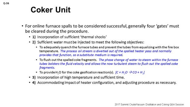
In a general sense, the term ‘spall’ describes the physical action in which chips or fragments are splintered and broken off of a larger solid body. There are several mechanisms that can produce a spall. In the context of the delayed coking process, however, the aim of furnace spalls is to break the coke layer off of the interior walls of the furnace tubes. This dynamic is produced by heating and contracting the furnace tubes in an alternating fashion over a relatively short time span to thermally shock and alter the fixed volume in the tubes themselves. Since the coefficients of thermal expansion of the metal substrate and the fouling coke layer are significantly dissimilar, the two layers grow and contract at different rates, which causes the physical detachment of the coke layer from the metal surface. The objective of thermal shock is to physically break the coke layer by using the force that is produced by thermal stresses to fracture the foulant layer. The first gate that must be satisfied in the spall, therefore, is to ensure that sufficient thermal shocks are incorporated during the procedure. Some are incorporated on the frontend of the spalling procedure, while others are incorporated on the backend of the spall.
During the spalls, boiler feedwater is lined up to the spalled heater pass, usually upstream of the convection section. Water addition serves three purposes, and I have them listed under the second bullet point in the slide. The three purposes are to:
-
Adequately quench the furnace tubes and prevent the tubes from equalizing with the fire box temperature. The process oil stream is diverted out of the spalled heater pass and normally provides that function, so a substitute medium is required.
-
Flush out the spalled coke fragments. The phase change of water to steam within the furnace tubes bolsters the fluid velocity and allows the now turbulent steam to flush out the spalled coke fragments.
-
Provide H2O for the coke gasification reactions.
The second gate that must be cleared is that sufficient water must be injected into the spalled heater pass to provide these three necessary functions. Water addition should be ratably controlled to target specific zones along the spalled heater pass and can be done by monitoring the progression of two wall temperatures in those specific sections over the course of the spall. Note: Boiler feed water or condensate is typically used as the source water because it needs to be free of inorganics/minerals (calcium, magnesium, sodium, etc.).
A combination of high temperature and time is needed to clear the third gate. The optimum value for both of these parameters must be determined through local experience while remaining within the temperature limits of the affected tube alloys. Procedurally, the time factor – or ‘length of hold’ step – should not be too rigid, given the fact that effective spalls can be performed to varying hold step lengths and dependent upon the morphology of the foulant coke, which can change and also be dependent on the feed slate. The combination of high temperatures and high steam velocities is required to micro-spall the coke layer via erosion and gasification reactions (where the steam can directly react with the coke to produce H2 and CO). The time factor simply provides a window for these two mechanisms to occur. The bulk of the coke removal during a spall operation may actually occur from micro-erosion and coke gasification, given the gradual change in tube skin temperatures that is typically observed during spalls.
The fourth and final gate is more or less dependent on the heater design. Typically, a heater pass is spalled individually while other the heater passes remain on oil. This approach creates the possibility that the spalled heater pass may be affected by a neighboring sister pass. The fourth gate simply acknowledges the impact that a sister pass can have on the spalled heater pass and accounts for its heat input. Simply stated, a sister pass may need to have its respective coil outlet temperature target lowered prior to the introduction of oil into the spalled heater pass so that the combined firebox heat fluxes do not adversely affect the spalled heater pass in an acute fashion. Experience has taught CITGO that as much as half of the spalling benefit can be squandered from the onset if the effect of the sister passes is not taken into account. Along the same vein, another consideration to preserve the benefits of a spall prior to the conclusion of the spalling operation – and once oil is reintroduced into the pass – is to ensure that the core outlet temperature targets for the spalled heater pass be ramped up slowly. This precaution is needed to prevent higher flux conditions during the period when the oil flow in the spalled pass is not yet sufficiently high to properly quench the tubes.
It should be noted that spalling operations are not as effective on the process convection tubes, because even the minimum water addition requirements may over-quench and prevent the convection tubes from getting hot enough for the spalling mechanisms to work as effectively. Fortunately, the process convection tubes generally do not coke up as severely or as rapidly as the furnace’s radiant tubes. Eventually, however, the loss of heat transfer along the process convection section can become limiting enough and impose a higher duty load on the radiant section (leading to more accelerated heater pass coking rates in that section). Because of this ‘diminishing return’ dynamic, a heater that is normally decoked with online spalls will also need to incorporate a steam/air decoke or a pigging operation – roughly after every three or four spalls – to better restore the performance of the convection section.
In summary, sometimes short spalls are successful; sometimes they are not. Sometimes spalls with less water injection are successful; sometimes they are not. Sometimes spalls at higher temperatures are successful; sometimes not. Generally, however, if furnace tube wall temperatures can be uniformly reduced by 150 to 200°F post-spall, then the spalling operation can be deemed successful. This result will typically occur if all four gates discussed above are satisfied. Of course, there are a myriad of other factors one must consider with the spalling operation, such as effects on coke morphology, the coke cutting operation, some additional reliability considerations, and effects on the heater pass outlet manifold. These other factors usually do not affect the performance of the spall itself; they just need to be considered.
LÉGARÉ (Andeavor Martinez Refinery)
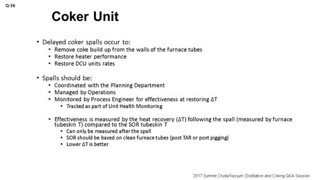
I will try to fill in some of the very few gaps that Héctor had in his talk. So, why is spalling efficiency important? If you are looking at a refinery where you are coker-limited, then coker spalling is essentially slowing down your whole refinery. It is really important that your Coker Operations team and your coker unit engineers are keeping a close eye on spalling to make sure that it is as efficient as it needs to be because it is really integrated into your planning process.
We will not go into why you do spalls, as that was already covered. Spalls really should be coordinated with the Planning Department. As I said, it is built into your plan, which is really managed by Operations because they will be the ones who will go through the procedural steps. Then, the unit engineer will be tracking the actual performance or the efficiency of the spall, which will be tracked as part of the unit health monitoring reports. As Héctor said, you cannot really tell how effective your spall was until it is done; so, online effectiveness is really just a myth and something that you should tell your manager that you cannot do. The effectiveness is really measured as a function of the delta T (∆T; temperature differential). That delta T is defined as the temperature difference between the post-spall start-of-run tube skin temperatures as compared to a baseline, which would be coming out of a turnaround or a physical pig. You really want to start to look at minimizing that delta T post spall because that will be the sign of true efficiency and effectiveness of the spall.
What can drive the efficiency of the spall? Héctor covered some of them factors. Obviously, one is the duration of the spall. Again, when you are in a planning situation and coker-limited, you will get a lot of pressure to minimize the spall duration. However, sometimes you will need to perform a longer spall. So, it is really important to keep that conversation fresh, and be upfront with the Planning Department.
The quantity and quality of the velocity steam you are using: Andeavor uses velocity steam, not boiler feedwater.
The next point is using a shock or continuous spall. The temperature of the spall will be temperature-dependent. So, with the shock spall, you will see temperature gradients playing a greater role as a continuous spall is more about velocity steam and constant temperatures.
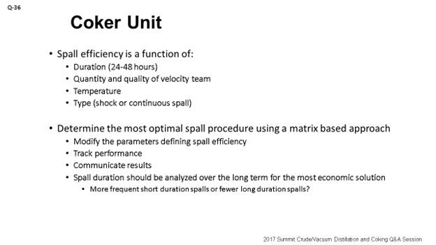
What can you do to optimize the spall approach? We came up with a chart, which you can see on the slide. The chart uses colors to measure performance. What do the colors tell us? Well, green means go; red means stop. The more green you see, the more delta T is being minimized and getting closer to zero. Red on the chart indicates that the spall did not go well. The point I want to make is that when a spall does not go well, you want to get with Planning right away and try to schedule another spall in that same pass as soon as you can. Because if you do not go after that pass right away, you may end up in a pigging situation. Like I said, green means it is directionally where we want to go. You can see there are different colors on the fonts, too. As we change the type of spall, we change the color of the font we use to represent the different spall durations utilized for the spall. So, the green and the red are the measures of the true effectiveness of the spall.
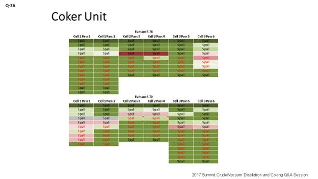
Some final thoughts: Optimized spalls are obviously going to help reduce lost profit opportunity; because when the efficient spalls are planned properly, they will be effective in getting the furnace performance back where it needs to be. Opportunity spalls are something that a refiner should really have in the forefront when looking at coker operations. ‘Opportunity spalls’ are the term we came up with when an opportunity essentially presents itself. For instance, you have some other upset in your refinery that has slowed down your coker. You have room on the coker rate, so you can go after a free spall essentially as long as you have the steam available to do that. Get your heater performance back up on track so that when you are able to push the coker again, you will not have to worry about that spall that was scheduled a week or two out.
I will tell you that the opportunity spall is something which needs to be ingrained in your culture; because as I have seen changes in the Operations team over time, they have lost sight of that opportunity. As a result, we have gone through an LPO (Lost Profit Opportunity) situation where we have had to cut back on crude runs only to come out and start the coker rates up again. And then within a week after raising coker rates, we had to slow down crude and coker rates again to spall. So, obviously, you want to try to avoid that type of coker slowdown. The last point is that the poor spalls really need to be addressed quickly. If you are not effective with a spall, you run the risk of going into a pig and having a shutdown.
LOGEROT (Prosys Inc.)
You have heard the first two guys talk about trying to develop what might be considered an optimum procedure for the spalling. Héctor spent a lot of time on the four gates. So, I am going to introduce the concept from process control. Once you have decided on your optimum procedure, how will you be sure that you will follow that optimal procedure every time? There is a mechanism that, in the process control world, we call ‘procedure automation’. You can leverage your automation tools. They will allow you to automate your spalling procedure. So, ultimately, you get to a point where the operator just presses a button and says, “Spall this pass,” and the control system goes back doing all the spalling.
Now what I heard these guys say, too, is that some of the steps are rigid and that you want it to be on exactly this flow rate for this time and that temperature. Some of them are more flexible. You can build the flexibility into your procedure automation system by allowing the operator ranges of set points or controls for a particular part or step of the operation. So, basically, if you can write down your procedures in a stepwise fashion and provide the operating conditions that you want in each step, then it can be automated. When you automate it, you basically ensure that your “Best Operator” is on board all the time. Your “Best Operator” is really that control system which is controlling it and telling you exactly which steps you want and in what order, as well as which control settings to use each time.
ROGER METZLER (Baker Hughes, a GE Company)
When you are performing repetitive spalls, do you see a point at which you begin consistently getting diminishing returns and you just know you are only going to be able to perform so many spalls before you will have to set up a pigging or a decoke?
GAMBOA-ARIZPE (CITGO Refining & Chemicals, L.P.)
After several decoking operations, the refiner gets to the point where the spalls are no longer as effective. Usually, the convection section of the coker furnace becomes limiting because the spall is not as effective at cleaning the convection section. So, over the course of three or four spalls, you may have to come back and do either a steam/air decoke or a pigging operation to restore the performance of the convection section. Fortunately, the convection section does not foul as severely. It fouls a bit slower. But because of the general inability to get the right temperatures in the convection section tubes during spalls, the spalls are not as effective in that section.
One of the other points I want to make is that if you do have a spalled pass that did not perform as well post-spall – say you have a heater with four passes and one of them did not do so well – and if you do not do what Eric said and go at it again and reestablish a better spall, then you will end up with an imbalance on the heater. That imbalance is what will drive the heater to foul up more severely during the next run.
TARIQ MALIK (CITGO Petroleum Corporation)
I heard various times for the online spall. Darwin had it at 16 to 24 hours, and I think Eric said 24 to 36 hours?
LÉGARÉ (Andeavor Martinez Refinery)
Forty-eight.
TARIQ MALIK (CITGO Petroleum Corporation)
Forty-eight. So, what tells you that you are done? I would like to be done in 16 hours, but I can never complete a spall in 16 hours.
LÉGARÉ (Andeavor Martinez Refinery)
The range I gave will be in the Answer Book section of the transcript. We were basing it on a 48-hour spall because that was what we needed to get the performance we targeted. What happened was that we did not have the right information from our Inspection Department. As far as the temperature limits, we could see limits on the heater and the outlet piping temperatures. So, once we established a higher allowable outlet temperature on the furnace outlet piping, we were able to spall at a higher temperature and get the performance we needed in 24 hours instead of 48.
TARIQ MALIK (CITGO Petroleum Corporation)
May I ask at what temperature?
LÉGARÉ (Andeavor Martinez Refinery)
The revised temperature was 1300°F.
TARIQ MALIK (CITGO Petroleum Corporation)
For the next question, I want to poll the panel. At what tube-metal temperatures do you trigger the decoke, spall, or pigging of the heater? Do you go to 1300, 1400, or 1275°F? What is that number you reach where you say, “This is the limiting temperature; now decoke the heater tube”?
GAMBOA-ARIZPE (CITGO Refining & Chemicals, L.P.)
I think ours is between 1300°F and 1350°F.
TARIQ MALIK (CITGO Petroleum Corporation)
Is that 9-chrome tubes or stainless?
LÉGARÉ (Andeavor Martinez Refinery)
We are in the same range of 1300°F.
TARIQ MALIK (CITGO Petroleum Corporation)
Thirteen hundred? I do have one more question for Jeremy on that heater that does 12°F fouling a day.
THEISS (Marathon Petroleum Corporation)
I said 6 to 12°F.
TARIQ MALIK (CITGO Petroleum Corporation)
Okay: 6 to 12°F. I just took the upper number. You said that there are three cells. How many passes per cell?
THEISS (Marathon Petroleum Corporation)
Two.
TARIQ MALIK (CITGO Petroleum Corporation)
Okay. Thank you.
ERIC LÉGARÉ (Andeavor Martinez Refinery)
Delayed coker furnace spalls are performed to remove the buildup of coke on the inner walls of the furnace tubes in order to improve furnace heat transfer and maintain unit throughput and efficiency. As furnace spalls require coker and sometimes refinery crude rate reductions, they should be planned and communicated effectively to the refinery’s Planning Department to ensure that crude and product inventories are managed appropriately. Effectiveness of the spall cannot be measured during the spall, so it is only after completion of the spall that effectiveness can be determined. The Coker Operations Team will manage the spalling procedure and communicate spalling results for each planned spall. Spall effectiveness should be captured as part of the unit’s health monitoring report and tracked on an ongoing basis.
Spall effectiveness is monitored by the process engineer – after the spall is complete – by comparing the furnace tube skins’ start-of-run (SOR) temperature after the spall with a post-pigging or post-turnaround SOR furnace tube skin temperature. If post-spall SOR temperatures do not meet expectations, the details of the last spall should be investigated as changes may be required to the spall procedure and/or duration and will need to be communicated to Planning. A poor spall can introduce an unplanned event in the refinery’s monthly plan to recover coker furnace performance before the coke may prove too difficult to remove in a spall and pigging becomes the only solution. Note that the Coker Operations Team should always be looking for a window for an “opportunity” spall to regain heater performance when little or no refinery impact would be incurred.
Spall efficiency is optimized by maximizing spall temperature, which is measured as the furnace pass outlet temperature. Work with your Inspection Department to determine the true limits of your furnace tubes and/or furnace outlet piping. One Andeavor site worked with a lower furnace outlet limit for a couple of years. This resulted in longer spalling durations as effectiveness was impacted by the temperature limitations. The Inspection Department reviewed the piping metallurgy and provided relief on the historical spalling temperature limits.
Quantity and quality of velocity steam (high pressure, dry) is important when determining the optimal spall conditions. Determining the type of spall technique – shock spall or continuous spall – will also affect the efficiency of the spall. Shock spalls will utilize a cycling of spall temperatures to try to break off the coke using a mix of hotter and cooler temperatures in the tube passes. Continuous spalls will use constant temperature and velocity steam to help spall the coke off the tubes.
Spall duration can be seen as a tradeoff between the number and duration of spalls per year. If your spalling effectiveness is not meeting the expectations of your Refinery Leadership Team, it is recommended that a plan be developed using a test matrix to determine the most effective spall method for your unit. Higher spall temperatures within established limits and longer spall durations are preferred, but optimization to minimize durations will always be requested by your Planning Department.
Below is an example of a test matrix which can be used to develop an optimized spalling technique. An Andeavor site created a table that utilized conditional formatting to compare spall effectiveness and spall technique to generate a visual tool to demonstrate overall spall effectiveness. Darker green means spall effectiveness closer to baseline, with dark reds indicating a poor spall. Font color is used to explain the duration of each specific spall. Parameters that were changed included duration and furnace outlet temperature. Changes led to a new spall procedure that takes 24 hours to achieve the same performance that spalls of 48 hours did a year ago. This modification reduces the LPO associated with planned spalls by up to half.
Year
2017
Process
Question 35: What are your major parameters and mechanisms that affect coker furnace fouling? Are there known effects from some specific crude properties? What are typical fouling rates, and how can they be minimized?
SOLOMON (Athlon Solutions)
Favorable coker margins have caused all refiners to take a good look at the coker furnace fouling and how we can extend our run lives and get more out of them. Two areas obviously within the furnace – the convection section and the radiant section. Look at two different ways of what is going on to understand what parameters and mechanisms are causing fouling. In the convection center, we are mainly looking at organic solids – obviously, the crude slate – to understand how the crude is behaving, identify the properties, and also look at steam quality. Then of course, down in the radiant section, we are looking more around operational issues. How are we managing the operation of fluid rates and steam rate, and in total, the bulk fluid rate? Mechanical; What tube diameter and metallurgy can be used? It is also important, as are the chemicals being used, to understand contaminants in the fluid such as sodium, asphaltenes, or iron. Understand the exact details of the crude slate.
Feed factors that obviously affect fouling are the asphaltene content, which is the biggest factor we were seeing, and understanding the stability of the asphaltenes. Understanding the types of inorganic solids is critical. There are various sources of inorganic solids – including corrosion byproducts, salts, and caustic injection – that we put into the crude, and various materials – clay and dirt – that are coming out of the formation, as well as all of the transportation issues. The main process for fouling is really destabilization of asphaltenes, whether caused by changes in pressure or the high cracking temperatures that exist in the furnace.
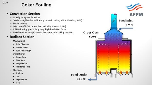
What we see is that the asphaltenes tend to be stabilized by resins and aromatics. When you get to high coking temperatures, those resins and aromatics start to crack and can form large-chain molecules that eventually reach the solubility limit; then, agglomeration and deposition starts to happen on the tube surface. The asphaltenes are also less stable in the absences of these resins and aromatics, and they start to deposit on the tube surface as well.
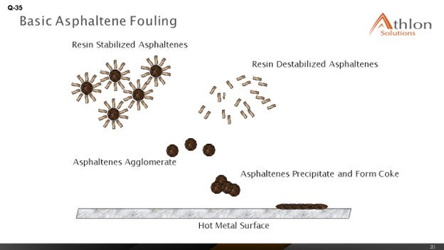
How do you minimize fouling and manage to remove some of the fouling that has occurred? There are various methods. Mechanical pigging can be done every two to five days. Steam-air decoking can be done at about the same duration: two to three days. Online spalling tends to be one of the favorites as it is being done 16 to 24 hours per pass. Then of course, well, being the chemical guy, anti-fouling chemistries have started to really show some differences in the ability to manage fouling and mitigate it.
THEISS (Marathon Petroleum Corporation)
Kevin alluded to a lot of the mechanisms behind fouling. I am going to touch on a little of Marathon’s experience. We see big differences, obviously relative to crude slate. Kevin talked about that. At the refineries processing a lot of heavy Canadian, we can see fouling rates between 6°F and 12°F per day. We have seen double the fouling rates for those refineries processing heavy Canadian crudes. Really, tracking fouling performance is key to understanding not only when to go spall or pig or do whatever to decoke, but also to understanding how variable changes can affect fouling rates. So, if you want to mess around with the unit and see if it extends out your cycle, as far as the heater is concerned, understand that the data is really important.
The graph on the slide is an example of what we use at Marathon to track heater performance and determine when we need to spall our heaters. This specific example shows a staggered spall. It is a three-cell coker furnace, and the spalling cycle is somewhat staggered based on fouling rates on each individual cell.
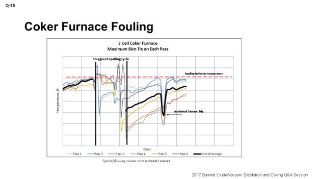
I also want to touch on is some of the process variables you can alter to help affect coking. Obviously, we talked about crude selection. It could be very uneconomical to go down that path to select your crude based on your heater fouling rates, but it is an option. You just have to look at the big picture to be sure that is the right decision to make.
Thermal cracking can be minimized by increasing velocity and decreasing heat flux and outlet temperature. There are some penalties with decreasing outlet temperature as you will lose some yield. Obviously, it could also lead to some foaming events in the drums. If you have the equipment such as feed preheat, you will want to do your best to maximize feed preheat to minimize heat flux in your heater, which will help reduce some fouling. We have also done some testing with velocity steam and determined that going up to about 1.5% of velocity steam is really the peak amount of benefit you will get from increases in velocity steam. Too high velocity steam can increase your back pressure and actually reduce your heater tube velocity.
TARIQ MALIK (CITGO Petroleum Corporation)
Jeremy, you said that you had a heater with a fouling rate of 6 to 12°F per day. That is very aggressive. To what have you attributed that? You mentioned Canadian crude, but you cannot profitably operate a coker with a 12°F-a-day fouling rate. That means in about 21 days, you are done with the run-length.
THEISS (Marathon Petroleum Corporation)
Now we are doing it. It is not ideal, but primarily crude slate driven. It is a refinery that runs a lot of heavy Canadian crudes.
TARIQ MALIK (CITGO Petroleum Corporation)
Is that a double-fired or a single-fired heater?
THEISS (Marathon Petroleum Corporation)
Double.
TARIQ MALIK (CITGO Petroleum Corporation)
Double-fired heater and 12°F per day. That is not in the ballpark. What excess oxygen are you running on this?
THEISS (Marathon Petroleum Corporation)
I would say probably bouncing somewhere around 5 to 7%.
TARIQ MALIK (CITGO Petroleum Corporation)
That is good. Is it balanced or natural draft?
THEISS (Marathon Petroleum Corporation)
It is balanced.
TARIQ MALIK (CITGO Petroleum Corporation)
Okay. It is not adding up but thank you.
KOUSHIK GUMASTE (Baker Hughes Incorporated)
There is not a lot of literature available on the specific effect of sodium. Do you guys have any definitive proof that sodium does destabilize and cause more fouling? I have only heard it by word of mouth.
THEISS (Marathon Petroleum Corporation)
Actually, we recently had a little experience with testing caustic additions in our crude unit and determining the effects of translating that result to sodium fouling in the coker. With our testing that we did, it was really hard to tell the difference in coker fouling when we varied the level of caustic injection in the crude unit. That being said, there could have been other variables going on at that time. The bottom line is that we did not see a significant step-change in furnace fouling when we did some of those trials.
GAMBOA-ARIZPE (CITGO Refining & Chemicals, L.P.)
Just a secondary comment about the sodium: As Jeremy described, one of the other coker-related concerns with sodium addition, usually added upstream in the crude unit at the desalters, is the potential for the caustic embrittlement of the coker heater tubes, depending on your alloy. It is a problem that should not be ignored. The same embrittlement risk exists for the drums. The sodium starts leaching into the metal at a temperature as low as 800°F. Most of the delayed coking process occurs above that temperature, and so embrittlement risk is a concern that should not be ignored with sodium.
TARIQ MALIK (CITGO Petroleum Corporation)
Sodium is a well-known coke precursor, so coker feed should typically be less than 10 ppm (parts per million) sodium going in. If you have 20 to 25 ppm, you will impact run-length on the coker. Sodium is not good news in coker feed.
ALLEN KAISER (Delek Refining Ltd.)
I want to tell you two stories. First, we were blending a tank of caustic for our crude unit for injection downstream of the desalter. Due to some misalignments, we pumped straight 50 Baumé caustic into the desalted crude stream. When that hit the coker, we gained 100°F on the radiant TIs (temperature indicators) in a matter of about 12 hours. So, sodium, yes, has a big impact on TMTs (tube metal temperatures). As a result, we began paying attention to sodium a little closer; and then, we started – stepwise – bringing down the amount of caustic we were injecting into the crude unit.
Secondly, when we started measuring sodium, it was in the 50-ppm range. There was a big difference in fouling rate. The fouling rate was about three times higher than it had been in previous cycles. So, as we lowered that injection rate and got the sodium under 20 to 15 ppm, like Tariq was saying, yes, fouling rates started coming back down. Now, we are back to our more typical 0.5°F-a-day range. We got it back down in a more typical range.
HAROLD EGGERT (Athlon Solutions)
I think part of the confusion, if you are doing data analysis on sodium in the feedstock, is because no one has really delineated between sodium as sodium chloride and sodium as a function of overfeeding caustic. I think there is some debate as to whether it is the sodium or the sodium hydroxide. Most of the issues around the caustic are anecdotal. Like Allen said, we know we overfed caustic and that created an increase. But just looking at the lab analysis of the sodium in the coker charge may mislead you; the convention being that sodium chloride is not as detrimental to furnace fouling as overfeed of sodium hydroxide.
WARREN LETSZCH (TechnipFMC)
I have a question for the panel. If you are building a new coker today, how will you design the unit to do the decoking? Would you do steam/air decoking? Would you do it with pigs? What would you put in for a brand-new unit?
LÉGARÉ (Andeavor Martinez Refinery)
I will respond since I have one of the newest cokers out there. They are all designed for online spalling.
LÉGARÉ (Andeavor Martinez Refinery)
Oh, Yes. Definitely.
ROBERTSON (AFPM)
And that is the next question.
GAMBOA-ARIZPE (CITGO Refining & Chemicals, L.P.)
Yes, we will address that topic in the next question. We would not let you down, Warren.
KEVIN SOLOMON (Athlon Solutions)
The major factors affecting coker furnace fouling fall onto three key areas: mechanical, operations, and feed.
Mechanical: Configuration and design elements of the furnace that have significant impact to fouling are:
-
Tube diameter, which affects residence time and pressure drop.
-
Burner type, which affects flame impingement and issues arising from dirty fuel gas; and,
-
Tube metallurgy and surface roughness: 9 Cr, 12 Cr, 316 to 317L. Different metallurgy have different max skin temperatures. Some can be 150°F higher, which allows for longer run lengths between coking.
Operational: Deviation from industry published operating parameters can cause or exacerbate fouling. The following guidelines should be followed:
-
Maintain flow rate (cold liquid): 6 to 8 fps, which is the hydrocarbon flow rate before adding steam.
-
Bulk fluid rate: 10 to 12 fps; includes oil and steam.
-
Operating temperatures: less than 750°F.
Feed: There are several specific issues related to the feed material that affect fouling. Factors found in the coker furnace feed that can cause or exacerbate fouling are:
-
Sodium levels in the crude.
-
Heptane insoluble-to-carbon residue ratio.
-
Asphaltenes content in the crude.
-
Understanding of the metals type and concentration.
-
Understanding the stability of asphaltene, with respect to the crude slate, can help predict fouling and permit actions to be taken to reduce fouling rates.
-
Inorganic solids, such as corrosion by products, filterable solids and salts, and sodium can come from a variety of sources.
-
Corrosion byproducts can originate from upstream operations such oil production, transportation, crude oil storage, slop products, and contamination in the velocity steam or boiler feed water.
-
Salts can be from the salt water in the oil producing formation and brine contamination occurring during transportation.
-
Caustic may result from injection into the crude to reduce overhead chlorides.
-
Clay, dirt, and catalyst fines may be introduced from upstream production activities, transportation, and refinery processes upstream of the coker furnace.
We have already discussed that asphaltene destabilization – and thus, precipitation – is a leading cause of fouling. Destabilization can occur because of several factors, such as changes in press, temperature (greater than 750°F), and acidity. Free-radical polymerization is the process by which we believe fouling occurs. During this process, aromatics and resins are cracked. The asphaltenes react to form longer chains; and once solubility is exceeded, deposition and agglomeration occurs on the surface of the tubes.
Fouling rates vary depending on the crude slate, feed rate, feed properties, operating conditions, and the condition of the coker furnace. However, there are several ways we can minimize the impacts of fouling. Some are physical, and others are crude management and chemical treatment.
Mechanical pigging steam-air decoking and online spalling are activities that can help remove fouling buildup, to a certain extent. During any of these operations, feed throughput is reduced.
Crude management is focused on understand asphaltene stability and ensuring that the crude slate is as compatible as possible to prevent issues. Analyzing crude slate and determining asphaltene stability can give us an indication of potential fouling issues.
Utilizing a proven coker furnace antifoulant injected ahead of the furnace can help to reduce the rate of fouling without the need to reduce feed rate.
JEREMY THEISS (Marathon Petroleum Corporation)
Causes of Coker Furnace Fouling
Quality of feed is the major parameter in coker furnace fouling. MPC coker heater fouling rates have increased significantly over the past ten years, especially on coker units that process heavy Canadian crudes. We attribute the fouling increase to higher volume percentages of asphaltenes associated with the heavier crude slate. Heavy Canadian crudes can contain solids from the mining operations and diluent used to process these crudes, both of which can destabilize the asphaltenes and result in high heater fouling rates.
Other contaminants such as inorganics can also increase coker furnace fouling. Inorganics tend to precipitate in the convection section, where it is difficult to remove with online spalls. Inorganics, such as sodium, are introduced with incoming crude or injected during crude processing to manage overhead corrosion. It is recommended to manage sodium content below 20 ppm in coker feed.
Finally, the classic fouling mechanism for a coker furnace is thermal cracking. Coke from thermal cracking normally accumulates in the lower radiant section of the heater. Typical heater coking rate due to thermal cracking is around 1 to 4ºF/day depending on the asphaltene level in the feed.
Fouling Rates
One of our coker’s heater fouling rates more than doubled in the past five years with an increase in heavy Canadian crude throughput. This specific heater used to conduct decoking every six months and now goes through decoking every two months. Most refineries in the mid-west that process heavy Canadian crudes experience heater fouling rates between 6 to 12ºF/day. Our mid-west refineries that have similarly designed coker heaters to our gulf coast refineries can experience double the fouling rates.
Within MPC, coker heaters that spall online evaluate a shutdown every two to three years to pig the heater and hydro-blast the transfer line. We normally see heavy accumulation in the convection section and transfer line during the cleaning. Fouling of the transfer line increases back pressure which suppresses vaporization and increases residence time in the furnace. After three years, we have seen a 50-psi increase in furnace inlet pressure due to transfer line fouling. We normally see run-length increase by as much as 50% after cleaning the transfer line/convection section.
Reducing Fouling Rates
If a crude selection change is not an option or economical, there are some changes that could directionally assist with heater fouling. Thermal cracking can be minimized by increasing velocity, decreasing heat flux, and decreasing coil outlet temperature. Heat flux is a function of heater design, heater charge rate, and heater inlet and outlet temperatures. Assuming that the heater is properly designed, and the burners are evenly distributed, the operator can reduce heat flux by maximizing feed preheat and optimizing heater outlet temperature. We normally set heater outlet temperature to target coke volatile carbon matter (VCM) around 10 wt% (weight percent) and meet coke hardness specifications. Although, managing heater fouling by lowering heater outlet temperature can result in more hot drums and foaming events. We normally set an upper limit of 12 wt% on VCM to prevent drum operational issues. Running lower heater outlet temperature will result in a yield penalty, which must be considered.
We have completed several tests on the effects of velocity steam. These tests show an increase in velocity steam rate helps to a point but does not provide much gain in heater run length when velocity steam is above 1.5 wt% of the feed. We think higher velocity steam rates can increase back pressure to the furnace, which in effect reduces the velocity in the furnace.
CHRIS CLAESEN (NALCO Champion)
The furnace firing and design has a big impact and needs to be studied and understood before other parameters are investigated. Feed properties, such as solids and metals content and stability, will impact the coking rates and can be controlled by proper blending and removal of solids/metals at the desalter. Antifoulants can further help reduce the coking rates due asphaltene instability.
GREG SAVAGE (NALCO Champion)
The coker furnaces are often a limiting factor to unit and refinery throughput. One factor limiting charge to the furnaces is spalling, steam-air decoking, or pigging, which is triggered when any tube in a pass reaches the maximum tube metal temperature (TMT) for the given metallurgy. The increase in TMT can range from 0.1 to upward of 10°F per day, depending on the fouling rate and furnace operation. Primary causes of coker furnace fouling are poor tube cleaning, overfired tubes, local high heat fluxes due to fuel or burner issues, inadequate mass velocity, high heat flux, and high fluid bulk temperature, as well as high levels of metals and solids in the bulk fluid. Poorly cleaned tubes can leave deposits and rough surfaces, which can serve as sites for fouling initiation during operation. Burner tip plugging due to solids and liquids in the fuel can cause poor distribution between the ports or port enlargement (as a result of erosion or oxidation), which can lead to high burner tip pressure, flame impingement, too few burners, uneven heat release, and fireside tube fouling from products of incomplete combustion and ash. These burner tip issues can cause localized hot spots that can promote the formation of coke deposits. Inadequate mass velocity leads to increased residence time and film temperature, as well as reduced turbulence. In low velocity regions, asphaltenes are more readily removed from the bulk fluid and are more likely to form coke. Low fluid velocity is a major contributor to furnace tube coking. High heat flux due to overfiring can be caused by poorly tuned instruments, fuel composition change, excessive throughput, high exit temperatures, or poor operational control. High heat flux raises the fluid film temperature and increases the coking reaction rate. High exit temperatures increase the fluid bulk temperature and therefore increase the potential for coke formation and deposition. Salts, dirt, caustic, and other contaminants in the fluid can catalyze asphaltene formation, increase coking tendency, and adhere to deposits.
Tube-side fouling deposits are typically a combination of corrosion and fluid decomposition products, as well as salts or dirt. These solids can adhere to the tube walls forming deposits, which interfere with the heat transfer and increase localized temperatures. These products are formed from a complex reaction dependent on the temperature of the wall film and the time of exposure to that temperature, i.e., wall film thickness (related to fluid velocity). Consequently, the heat flux and the mass velocity heavily influence the rate of fouling. Coking reduces potential unit run lengths because it increases heater tube temperatures to near metallurgical limits and also increases pressure drop in the heater, causing hydraulic limitations. Reducing the frequency of coking incidents and the rate of coke formation is thus important to increasing plant utilization.
Coker heater fouling is promoted by thermal destabilization and precipitation of asphaltenes followed by dehydrogenation of the deposited species at the furnace tube temperatures to form coke. Asphaltenes are kept suspended in the feed through resins that are attached to the particles. As the feed is heated, the resins increase in solubility and detach from the asphaltene particles, which causes the asphaltenes to precipitate. The asphaltene particles then lay down on hot surfaces and form coke deposits. The formation of asphaltene precipitate and degradation to coke can be catalyzed by iron, sodium, and vanadium. Tube wall roughness from corrosion, fabrication, poor mechanical cleaning, or deposition of asphaltene particles can act as a coking initiator.
The furnace exit temperature controls the flow of fuel and the distribution of feed to the passes and can be adjusted to increase cracking and improve yields. Consequently, proper control of the exit temperature and instrument tuning is important to optimizing unit profitability while minimizing the fouling risk. Burner tips that are frequently taken out of service increase the risk for formation of localized coke deposits. During spalls, burners can be taken offline to reduce the heat flux. Removing burners rather than controlling the fuel gas flow during a spall can lead to localized hot spots and formation of coke deposits.
Hot air can increase combustion efficiency, but it has also warped air distribution equipment at some refineries, which has caused some uneven heat flux distribution, and contributed to fouling. Some refiners lack sufficient O2 sensors in the firebox in each pass. At least three O2 sensors are recommended to ensure proper combustion and distribution. Excess O2 is controlled, depending on coker margins, and some refiners have found that higher excess O2 reduced spall rates. Additionally, CO meters can indicate incomplete combustion and the need for additional O2. Air and fuel gas distribution issues can result in the firebox ends being consistently colder than at the center, which increases the risk for the formation of localized coke deposits. Also, sagging in tubes – due to loss of mechanical support – can change flows and heat distribution, leading to hot spot development.
Cleaning of the furnace convection section can be done with dry ice. However, limited mobility and access can restrict the amount of surface that can be reached. Despite the limitations, recoveries of over 100°F have been found by refiners. External fouling of the convection section results in elevated heat flux in the radiant section, which increases the formation of coke deposits. Poorly cleaned tube internals can leave deposits and rough surfaces, which can serve as sites for fouling initiation during operation. After cleaning a tube, the temperature should consistently recover; otherwise, the cleaning may not have been effective.
The total heat flux is calculated using the fuel gas rate, fuel energy content, and tube surface area. Usually, the heat flux in the radiant section is 70 to 80% of the total heat flux and should be compared to the design maximum. Mass velocity is calculated using the cross-sectional area of the tubes, the mass flow rate, and the steam injection rate. Generally, the recommended mass velocity is between 350 to 450 lb/ft2-sec (pound per square foot per second). Steam is often injected for safety reasons, to change partial pressures, and to increase the velocity through the heater. A general guideline for steam injection is 2% by weight.
Coker heater tube fouling rate can be controlled through firing rate, velocity steam, and specialty chemicals. The most effective method of controlling heater tube fouling is increasing mass velocity, followed by reducing heat flux. Blending of slurry oil, increased recycle, or even light coker gasoil into the feed have each been effective at reducing furnace fouling rates, but generally with economic penalties. Laboratory simulation of blending these components into the coker feed can indicate the estimated benefit for a full economic evaluation of these options.
When process parameters are within the recommended envelope and other blend streams are not economical, proper injection of chemicals can help reduce the fouling rate. The coker heater protection program implemented by NALCO Champion uses a combination of passivation, dispersion, and coke suppressant chemistries to reduce the fouling rate. A phosphate-based filmer passivates metal surfaces, reducing activity, thereby inhibiting the metal surface’s ability to catalyze the formation of coke from asphaltene particles. An asphaltene dispersant stabilizes the resins that keep the asphaltene particles dispersed and therefore reduces the potential for deposition. Inorganic dispersant chemistry reacts with reactive sites carried in the coker feed, which initiate the formation of coke deposits.
Year
2017
Process
Question 33: What conditions are tied to fired-heater shutdown interlocks? Do these cause an immediate shutdown, or are there any time delays built into the logic? If so, how long of a time delay do you use? Are there any operating conditions that would allow interlocks on fired heaters to be bypassed?
THEISS (Marathon Petroleum Corporation)
As far as interlocks being tied to fired heaters, at Marathon, we rely heavily on API (American Petroleum Institute) 556 to develop our internal practices. Inside our internal practices, we have two main potential problems we are trying to combat: preventing an explosion due to uncombusted fuel and preventing a tube rupture that can lead to a fire or an explosion. On all of our fired heaters, we have interlocks for low- and high-fuel gas pressure and loss of process flow. For our balanced draft heaters, we include loss of airflow, high furnace pressure, and loss of flame. For forced draft and natural draft, we include all of those, the exception being furnace pressure.
We do allow shutdown time delays on several components. It is really a matter of looking at each one on an individual basis. We developed a lot of our guidance on time delays based on API 556. The current version of API 556 no longer has that specific guidance, but I think they are looking to try and include it again. Regarding time delays, we allow time delays on fuel gas pressure, firebox pressure, flame detection, process flow, process temperature, and level, if applicable.
As far as bypassing interlocks, we generally do not allow bypassing of shutdown systems. There are some exceptions. Obviously, performing maintenance is a big one that we look to allow. Some of our facilities actually have an automated report from the DCS (distributed control system). If there is something bypassed on a shutdown system, a notification via the report gets pushed out to the Operations Group. With this report, Operations can tell if something was placed in bypassed that should not have been. We do have certain operating procedures that allow bypassing of ESD (emergency shutdown) systems; but in general, we do not allow any other bypassing.
We do have some startup and shutdown provisions, particularly on heater interlocks. We have arming logic that initiates once you have a specific condition established. The logic is armed and ready to shut down the heater if we have greater than 50% of the burners lit and achieve a loss of flame signal. There are also turndown scenarios when the unit is turned down. The logic will arm to “all out of all” trip until greater than 50% of the burners are lit.
LÉGARÉ (Andeavor Martinez Refinery)
Andeavor’s procedures are similar to Marathon’s. We have a series of standards that we created based on API 556 and NFPA (National Fire Protection Association) 85 guidelines for heaters and fired boilers. The standard goes into a lot of detail around levels of instrumentation required on both the process side and the fuel side of the heater. Being in California, we also have requirements for CEM (Continuous Emissions Monitoring). The State outlines the requirements for CEMs as well. Chris McDowell of Andeavor is in the audience today. She can speak to all we need to do to comply with the regulators in the San Francisco Bay Area. The protective systems are also clearly defined in our standard; the recommended instrumentation levels are also there.
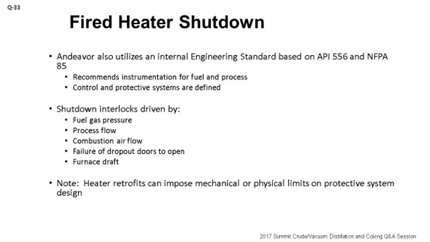
The next slide shows some of the time delays we outlined in our standard as well. I will not go through each one, but you can see that they are all specified with ranges. In addition, there are also valve travel allowances that vary depending on the size of the valve. The point I do want to make, though, is that a lot of these standards apply to new construction. When you are dealing with a retrofit, the approach can change. The proverbial “it depends” comes into play where you need to look at your physical layout of your heater or furnace and see what you actually can accomplish. So, it is really best to work with your technical personnel or technology suppliers and SMEs (subject matter experts) to figure out what exactly you can achieve to get to the inherently safest solution.
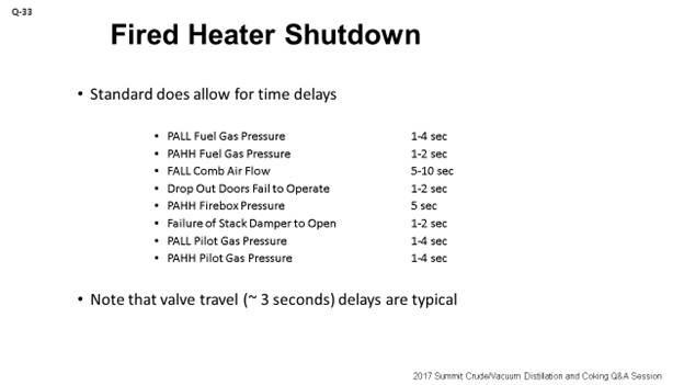
As far as bypasses, we operate in a way that is very similar to what Jeremy said. I will add that Andeavor also mandates that you have a procedure in place to allow for the bypass. In the event you do not have a procedure, the MOC (management of change) policy kicks in. The requirement for that MOC is that you have a clearly defined mitigation plan to deal with the bypass. The point I do want to make, which is what I have seen, is that that mitigation plan does need to involve the right level of personnel in your organization. You want to engage your instrument engineers, furnace SMEs, and process engineers, not just try to bypass the whole system to come up with the mitigation plan that is achieved at the end of shift, but which may not have the required integrity around the technical review. It is important to make sure that the mitigation plan is done properly.
In addition, the policy we have also outlines various levels of organizational approvals depending on the amount of time that the system will be bypassed. For example, if you are looking at a three-day bypass, an Operations Superintendent has to buy off on it. If it is a three-week bypass, then the Ops Manager is the one who gets involved. Lastly, what we do with these mitigation plans is table them. We try to keep them in a file so that in the future, if we have to do a similar bypass, we can at least use that mitigation plan as a solid starting point.
MIKE ADKINS (KP Engineering, LP)
One of these subsets that you guys touched on that, from a design aspect, KPE would get involved in a lot is purging. Of course, end user always want to try to increase the purge rate to get through that purging process as quickly as possible. Some of the heaters KPE has seen have steam eductors on them, purge air blowers, or just straight steam into the heater. My question is to you guys who are refiners. What do you typically prefer and like to use during that purging sequence?
LÉGARÉ (Andeavor Martinez Refinery)
We are not typically using steam for purges. We get the fans started and use them to purge the system.
TARIQ MALIK (CITGO Petroleum Corporation)
Eric, I think you had the time delay reflected on the screen, right?
LÉGARÉ (Andeavor Martinez Refinery)
Yes.
TARIQ MALIK (CITGO Petroleum Corporation)
What is the purpose of having a four-second time delay? That was about the maximum in one of them. So, in four seconds, what are you going to accomplish? You cannot react to these alarms.
LÉGARÉ (Andeavor Martinez Refinery)
No. I think, like Jeremy said earlier, the API standards specify these time delays. I think this is like a legacy system that we still have in our standard.
TARIQ MALIK (CITGO Petroleum Corporation)
I thought the purpose was to give the board operator a chance to react or do something to make sure they are not spurious or are actually happening. I know some controls are touchy over there. But a four-second delay? You might as well not have a time delay.
LÉGARÉ (Andeavor Martinez Refinery)
Yes. I do not think we are looking at really four seconds for an operator response. It may just be four seconds to deal with the blip in the instrumentation and get a balancing out of the signal.
TARIQ MALIK (CITGO Petroleum Corporation)
You have a warning system on this? You have multiple instrumentations – two out of three – at the SIL 3 (safety-instrumented level 3) or SIL 2 level?
LÉGARÉ (Andeavor Martinez Refinery)
That is correct.
TARIQ MALIK (CITGO Petroleum Corporation)
Okay. My follow-up question for the panel actually has to do with the heaters. Do your heaters have explosion doors, or have you done away with them, sealed them shut, or thrown them away?
LÉGARÉ (Andeavor Martinez Refinery)
We still have some of them in our furnaces.
THEISS (Marathon Petroleum Corporation)
Yes, I am sure we still have some, but probably not all. We have some new construction that may exclude them.
GAMBOA-ARIZPE (CITGO Refining & Chemicals, L.P.)
Yes, we still have them.
CHRIS STEVES (Norton Engineering Consultants, Inc.)
Jeremy, you mentioned flame detection. Are you doing that on all of your heaters and all burners individually, or are you looking at trying to just verify if there is any flame in the firebox? How does that work?
THEISS (Marathon Petroleum Corporation)
Most of our heaters, especially the new designs, have flame detection. I would say there are very few within Marathon that do not have flame detection within the system.
BILL CATES (Hunt Refining Company)
Are you doing the flame on the main flame or are you doing a pilot?
THEISS (Marathon Petroleum Corporation)
In some applications, both.
EREMY THEISS (Marathon Petroleum Corporation)
Shutdown Interlocks
Marathon Petroleum Corporation (MPC) standard practices rely heavily on the guidance recommended by API 556. Most of our heater shutdown interlocks are derived from this API Recommended Practice. Our internal practices are intended to prevent a heater explosion due to uncombusted fuel in the firebox or a tube rupture that can lead to an explosion or uncontrolled fire. Specific interlocks that result in a fired heater shutdown, as defined in our standard practice, include low/high fuel gas pressure and loss of process flow. Further guidance on alternate heater configuration is also given. Balanced draft heaters shutdowns include loss of air flow, high furnace pressure, and loss of flame. Although forced draft and natural draft heaters’ interlocks do not include high furnace pressure, they do include loss of flame.
Shutdown Time Delays
We do allow certain time delays within the SIS logic. These delays were derived from original API 556 guidance. The length of the time delay is based on acceptable risk tolerance evaluated independently by MPC subject matter experts. MPC has time delays on the following shutdowns: fuel gas pressure, firebox pressure, flame detection, process flow, process temperature, and level (where applicable). Currently, API 556 does not include time delays, but including guidance on time delays is under consideration for the next revision.
Interlock Bypass Philosophy
In general, we do not allow bypassing of shutdown interlocks during operations. We do provide guidance to bypass under specific instances of maintenance. During periods of maintenance, alternate monitoring plans are established with Operations to ensure that the intent of the shutdown system is intact. There also may be special circumstances conducted that involve bypassing, but these instances will only be executed under a specified procedure. When possible, we recommend that these special procedures be implemented through operation mode selectors that an operator can select to automate the logic. If deviations to the procedure are required, an MOC is necessary to execute the deviation.
For periods of startup and shutdown, we develop arming logic for flame detection to prevent unnecessary trips, which can lead to unsafe conditions. For startup conditions, this logic is armed once the first burner detects flame for “all out of all” voting; meaning, a loss of flame on all burners is a vote to trip. Once greater than 50% of the burners detect flame, the logic reverts to the normal shutdown logic, which is typically that less than 50% of the total burners detect flame is a vote to trip. To manage process turndown scenarios, we also have low-fire mode which will revert back to “all out of all” voting logic.
ERIC LÉGARÉ (Andeavor Martinez Refinery)
Andeavor utilizes a series of internal Engineering Standards to address fired heater instrumentation, control, and protective systems. These standards were developed using the content of API 556 and NFPA 85. Andeavor’s standards define the required and recommended instrumentation for the fuel and process sides of gas fired heaters. The control and protective systems are based on instrumentation mandated by the standard. Examples of required instrumentation include fuel gas pressure; combustion air flow; firebox pressure and temperature; excess oxygen; draft; and, where applicable, flue gas analysis via CEMS for regulatory compliance.
Protective systems and allowances for overrides, bypasses, and permissives are also defined in the standard to allow for safe and effective design and operation of fired heaters. Andeavor’s standards protect against the accumulation of combustibles in the firebox, overheating of heater tubes, high/low draft and flameout. Instrumentation linked to the protective system [Safety Instrumented System (SIS)] should be independent of the control instrumentation.
The design of the protective system does allow for time delays with allowable ranges provided as follows:
PALL Fuel Gas Pressure 1-4 sec
PAHH Fuel Gas Pressure 1-2 sec
FALL Comb Air Flow 5-10 sec
Dropout Doors Fail to Operate 1-2 sec
PAHH Firebox Pressure 5 sec
Failure of Stack Damper to Open 1-2 sec
PALL Pilot Gas Pressure 1-4 sec
PAHH Pilot Gas Pressure 1-4 sec
Note that the above information corresponds to new heater designs. For retrofit projects, it is recommended to work with your project team and subject matter experts to implement the design that best satisfies the standard with which you are trying to comply.
Startup overrides are required in the protective functions of the control system to allow for the startup of fired heaters. The operator’s display will include a notification that the protective function is overridden during startup conditions. These overrides will allow for startup steps such as furnace purges and burner light off. Once the startup conditions are cleared, the protective system is engaged automatically by the DCS.
Bypasses on input devices and/or protective systems for maintenance, calibration, and testing are permitted in accordance with the site’s operating and emergency response procedures. Sites can manage these bypasses via Operations or Maintenance procedures or MOC, if procedures do not exist. A mitigation plan should be part of the procedure or MOC being followed, and the plan must be communicated to all affected personnel. Note that the plan is only as robust as the quality of review that went into its development. Ensure controls and SIS experts are consulted when developing a mitigation plan.
The plan should also be kept in a location accessible to the board operator. Management approval of the mitigation plan is required with escalating levels of responsibility defined as a function of the bypass period. As an example, a three-day bypass period requires the approval of an operations superintendent. A three-week bypass period requires the approval of the Operations Manager. Bypassed alarm status should be visible to the board operator. The protective system and/or input device should be put into service immediately following completion of the work. The mitigation plan should be logged for reference in the future.
RICHARD TODD (Norton Engineering Consultants, Inc.)
All fired heaters should be equipped with safety instrumented systems (SIS) that take the heater to a “safe state” upon detection of a potentially unsafe condition. Recommendations for the implementation of these systems can be found in API-556 “Instrumentation, Control, and Protective Systems for Gas Fired Heaters”. Typically, most heaters should be equipped with instrumentation and logic to remove fuel gas from the heater on the following conditions:
-
Low fuel gas burner pressure,
-
High fuel gas burner pressure,
-
Low process flow,
-
Low combustion air flow (if a heater with FD fans), and
-
Loss of flue gas removal (if a heater with ID fans).
Other process conditions may require automated heater shutdowns as well. A HAZOP with LOPA should be conducted to determine if additional safeguards are required.
Time delays are usually built into the logic of the SIS logic solver to prevent spurious trips due to instrument noise. A thorough review of the system and the calculation of process safety times (the time to reach an unsafe state from the start of a process upset) should be conducted to be sure that the chosen time delays do not exceed the process safety time. Multiple instruments with voting logic (i.e., two out of three voting) are also used to improve SIS reliability and to decrease the frequency of spurious trips.
Instruments that are used in SIS should be equipped with bypasses to allow for maintenance to be conducted with the heater in service. The use of bypasses should be managed with a safety device bypass procedure that requires appropriate reviews and approvals so that the instrument can be bypassed without impacting the safety of the equipment. Typically, bypasses on safety instrumentation should not be utilized during process upsets or due to unusual operating conditions. Startup of heaters may require the high and low fuel gas pressure trips to be bypassed for a short amount of time as burners are being initially lit, but this bypass can be safely managed in a well-designed SIS that may add additional safeguards and that will automatically remove the bypass after a prescribed period of time.
Year
2017
Process
Question 34: What are your current protocols, practices, and concerns for using wireless communication between field instruments and the control room? Would wireless communication be acceptable for monitoring only, or is control allowed as well?
LOGEROT (Prosys Inc.)
The question asked about the protocols. But rather than naming the protocols, I think it would just be best to describe what the installation looks like. With wireless transmitters that are in use, you are usually installing a mesh network and you have a Modbus gateway connected to the DCS. You have a separate wireless gateway that is connected to that as well, and the wireless gateway connects to all the transmitters. Each one of the transmitters can actually act as a hub and is able to receive and transmit data with the other transmitters. That way, transmitters can find other transmitters close by and multiple pass-backs to the gateways. So, if a transmitter is out of service for any reason, the other transmitters will basically find pathways around it to get communication back to the wireless hubs.
Note that in this kind of arrangement, you need to have a robust gateway; because basically, the wireless gateway represents a single point of failure. Therefore, most installations use redundancy there, sometimes triple redundancy, to make sure that communication stays open.
Where are the main uses of wireless in refineries today? In our experience, they are usually remote areas of the refinery where a signal and power wiring are not easily run out. The big advantages, obviously, are cost savings, conduit wiring, and cable trays. Inside the battery limits of, say, a crude unit, wireless is not as common. Where used, it is usually for auxiliary type of measurements such as corrosion monitors, vibration monitors, additional temperatures, and pressures that are not central to the process. You might also consider wireless technology, as sometimes we have outside operators who have handheld devices that are wirelessly connected back to the control room. For that one-ring device, there will also be a network of gateways available for the wireless device to communicate back to the control room.
What are the concerns associated with wireless technology? The first real concern is cybersecurity. I mean, everyone is concerned about security these days. Basically, every wireless device and transmitter in your plant represents a potential entry point for intruders. So, you have to be very careful to put in strong security protocols to make sure that intruders will not get into your network. What can happen from an attacker? An attacker can jam your signals. You could lose proprietary data, and – worst of all – an attacker could end up gaining control over part of your process. You really do not want that to happen, which is why security is a big concern when using wireless. Second is overall reliability. Basically, we have been using hardwired signals for decades. Wireless signals are just not as robust in today’s technology as are the hardwired signals. For example, how often do you have to go reset the Wi-Fi in your house? That is an example of when wireless is not as reliable as it could be.
The last part of the question had to do with whether wireless is acceptable for control or if it is just for monitoring purposes. When I say ‘control’, I am talking about closed-loop control where you have a wireless transmitter communicating to the control room and there is a control action. They then signal out to the final element, usually a valve. It is probably also wireless, but it might be hardwired; but there is at least some component in that closed-loop control that is wireless. Our typical answer is that it is just not used very often for closed-loop control, and it is usually not recommended. One of the problems is battery life, because the transmitters you are using in the field are battery-operated. If you have a very high refresh rate – like, typically, a five-second refresh rate, then your batteries will die too quickly. That is one reason why you would not want to be using wireless for controls. So, generally speaking, it is not recommended or used. However, that is not to say that wireless control will not, sometime in the future, be relatively common.
THEISS (Marathon Petroleum Corporation)
The chart on the slide is really the internal guidance we use at Marathon. You can see that for what we call Class 0 and Class 1, we do not allow wireless communication, which basically inputs to an SIS (safety instrumented system) or some control point that is detrimental to the process. An example of a detrimental control point would be an FCC (fluid catalytic cracking) reactor/regenerator pressure differential transmitter for which we would not allow wireless control.
There are a couple of applications in which we allow control. I do not think they are widely used within Marathon; but with some corporate guidance and corporate technologist approval, we can use them wireless for control. These would be considered Class 2. An example would be a tray tower control for a temperature.
As you move further down the chart to Class 3, you can see an example of where you have the overhead water boot. You have a remote signal that goes into the board, but it relies on the operator to go out and make the move to drain that water boot and start to pump or open up a valve. Class 4 and Class 5 are really for informational purposes. My example for a Class 4 would be a secondary alarm on a tank where you have a primary alarm that is hardwired in and a secondary level or a backup level that could be used remotely. Class 5 would be temperature indication on heat exchangers just to gather data for fouling.
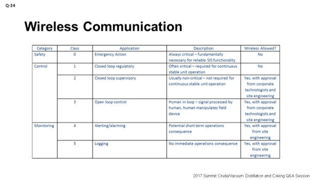
JEREMY THEISS (Marathon Petroleum Corporation)
Technology continues to progress in this field. Since 2011, we have had guidance that allows some usage of wireless instrumentation, but this technology is limited based on application. The table below identifies our stance on certain applications.
|
CATEGORY |
CLASS |
APPLICATION |
DESCRIPTION |
WIRELESS ALLOWED? |
|
Safety |
0 |
Emergency Action |
Always Critical: fundamentally necessary for reliable SIS functionality |
No |
|
Control |
1 |
Closed-loop regulatory |
Often Critical: required for continuous stable unit operation |
No |
|
2 |
Closed-loop supervisory |
Usually Non-Critical: not required for continuous stable unit operation |
Yes, with approval from corporate technologists and site engineering |
|
|
3 |
Open-loop control |
Human in Loop: Signal processed by human, human manipulates field device |
Yes, with approval from corporate technologists and site engineering |
|
|
Monitoring |
4 |
Alerting/alarming |
Potential short-term operations consequence |
Yes, with approval from site engineering |
|
5 |
Logging |
No immediate operations consequence |
Yes, with approval from site engineering |
Examples:
Class 0: Inputs to a Safety Instrumented System
Class 1: FCC Reactor/Regenerator pressure differential transmitter (used to manipulate flue gas stack valve)
Class 2: Tower tray temperature
Class 3: Water boot high/low level where control or field operator starts/stops a pump or opens/closes valve
Class 4: Storage tank secondary level alarm
In most of the approved applications, redundant wireless gateways are required to minimize disruptions to a failed gateway. Other points to consider for determining if wireless is acceptable include the required scan rate of the application, wireless distance limitations, and potential for wireless interference. Guidelines should be made to ensure battery life or alternate power to the wireless device is sustained and has monitoring capabilities.
DARWIN LOGEROT (ProSys Inc.)
Wireless Protocols
Rather than naming the protocols in use, it is probably better to describe the installation. Where wireless transmitters are in use, they are often installed in a mesh network similar to cellular towers or a Wi-Fi network with multiple hubs. A Modbus gateway is connected to the DCS and to the wireless gateway that is connected to all the transmitters. Each wireless transmitter acts as an individual hub and is able to receive and transmit data with others. This way, a transmitter can find other transmitters close by and have multiple paths to the wireless gateway. If one or two transmitters are out of service, the remainder will adjust to provide continuous communication.
In this arrangement, a robust wireless gateway is important. If only one wireless gateway is provided, it can represent a single point of failure, potentially losing view of all instruments using that path to the DCS. Users will typically install redundant gateways to mitigate this.
So, where are the main uses of wireless technologies in refineries today? The locations are usually remote where the signal and power wiring are not readily available. The big advantage is cost (savings in conduit, wiring, cable trays, power distribution, etc.) and the ability to monitor remote data, such as in a large, spread-out tank farm.
Inside a refinery process battery limit, use of wireless is not so common. Where it is used, some of the more common wireless applications are in corrosion monitors, vibration monitors, and additional temperature and pressure monitoring on vessels and exchangers (auxiliary to the hardwired temperatures and pressures).
Another use of wireless technology is for hand-held devices used by field operators. With this arrangement, another mesh network is employed to connect the wandering device to the DCS. The field operator can use the device to monitor operating conditions, execute periodic rounds, and take notes regarding observations. Major DCS manufacturers are offering this technology as an extension of the control system, but the control itself is done with hardwiring; only monitoring and setpoint adjustment are done through wireless.
What are the concerns associated with wireless technology?
First and foremost is cyber security. Every wireless device represents a potential entry point for an intruder. Security protocols are better and stronger now than ever, but many potential users are still reluctant to install extensive wireless devices. Security concerns include the possibility of wireless signals being jammed by an attacker, potential loss of proprietary data, or, worst of all, an outside intruder gaining control of part of a process.
The second concern is reliability. Wireless communication generally is less robust than hard-wired connections.
A third concern is the data refresh rate and its connection to battery life. For example, a one-minute update rate on the transmitters was tied to a life of about 10 years, whereas an update rate of four seconds reduced that life to two years. The relationship between refresh rate and battery life, of course, impacts how wireless can be used for basic control and impacts wireless maintenance costs.
So, is wireless communication acceptable for process control?
Allowing for a slightly wider definition of “wireless control”, it is in widespread use today – the plant radio. For example, the console operator can contact the outside operator: “Hey, go open/close the bypass valve around the control valve that is not working.” But more seriously, purely wireless communication for process control in a refinery is seldom used or recommended, especially in a unit that is tightly connected geographically, such as a crude unit or FCC. Where wireless communication is in use, it is almost exclusively for monitoring only, primarily due the problems outlined above. The closest approach to wireless control is using the handheld devices to adjust setpoints. The control itself is still through hardwire communications from the transmitters to DCS controllers and to the valves.
That said, there is no reason to expect that as technology improves, the current problems will not be overcome, at least in part. Perhaps future refineries will include widespread use of wireless process control.
Year
2017
Process
Question 26: How are developments in hydroprocessing catalyst adjusting to changes in feedstock quality? Are the new developments able to cope with and provide high activity with varying feedstock severity?
AL-FUDHAIL (Saudi Aramco)
It is quite fitting for this question to follow the one before it. As we know, in feed to the hydrocrackers, hydroprocessing and hydrocracking are becoming more and more refractive and difficult. This challenge is leading to the need to increase the capability of the treating catalyst-to-hydrogenation capabilities. Of course, with the coker gasoil and the asphalted oil, hydroractive material increases in the fraction of the feed. Operating the light coker, as well as units with very low recycle, to reduce coke nick, heavy coker gasoil becomes highly refractive.
There are basically two ways of combating that new, elevated refraction. One, of course, is with catalyst development. Another is to adjust the catalyst reactor’s loading. By means of layering your catalyst load, you will be processing Type I treating catalyst and Type II, as well as utilizing into immediate activity those catalysts, like light-cracking catalyst, which is used to denitrify and saturate the feed. Of course, Type II treating catalyst has a much higher hydrogenation function. This trend of using intermediate cracking catalyst to finish the pretreatment is gaining ground as opposed to using nearly amorphous silica and alumina catalyst, as was done in the past.
Modern cracking catalyst also uses a mix of traditional Y zeolite along with beta for optimum cetane with low cold-flow characteristics. This technique optimizes hydrogen consumption and reduces the cold flow properties for the distillate while maintaining optimal cetane index. That is a small point into the distillate cut.
Now when processing VGO from ebullated bed hydrocracking that is extremely aromatic, there will be a bulk-metal hydrotreating catalyst sandwiched between Type I and Type II. A treating catalyst is used to ensure that VGO is treated to meet feed quality for the FCC or second-stage catalyst in a maximum convergent unit. In such units, processing ebullated VGO second-stage catalyst requires high hydrogenation capabilities, which leads to the increased use of NovoMetal™ catalyst.
JOHNSON (Motiva Enterprises LLC)
In Motiva, we have seen advances in technology with the catalyst generations gaining more activity not only in VGO service, but also in distillates.
We have discovered that when evaluating a catalyst selection, depending on the unit configuration, we can unlock potential with not only catalyst, but also with hardware adjustments to extract more value from the catalyst, in terms of cycle length and sustaining yield over the cycle. In short, we have not seen the issues where the catalyst companies are not keeping up with the changing feedstocks with which we are dealing.
SCHOELLKOPF (Advanced Refining Technologies)
I will basically echo much of what you have already heard. We are seeing more and more difficult molecules that need to be processed. Not only are there complicated molecules, but they are making up a higher percentage of the feed. Therefore, it takes some innovative approaches to the catalyst system design to resolve this challenge. The conventional methods are no longer necessarily sufficient. More of a good thing is not necessarily the optimal solution either. That is, you do not necessarily want to go for high HDN (hydro denitrification) or high alumina for HDN processing when you are also processing some other highly reactive feeds; for example, heavy coker gas oils. So, we generally just take feed from the refiner and tailor our loads based on what the refiner wants in the products.
PAPPAL (Valero)
I think there are a couple of universal rules in hydroprocessing or hydrocracking. You can never have too much reactor volume, and you can never have too much catalyst activity. As catalysts improve, refiners will take advantage of catalyst activity and reactor volume.
TRAVIS KIRK (Haldor Topsoe, Inc.)
I just want to stand and say that it is key for catalyst suppliers to keep up with the increasing demand on activity by making sure we have a fundamental understanding of the surface science. That way, you will be able to optimize the different parameters of the catalyst with respect to 1) pore size distribution, 2) pore volume of the catalyst, and 3) the catalyst surface area, such that you can tailor those parameters to the type of service for which you are designing the catalyst, as well as to the severity of the feed that you are treating.
Also, with the increase in the severity of feed, you will see an increase in the number of metals on the catalyst. So, you need good metals trap catalyst. We are seeing a lot of arsenic and silicon – even in straight-run components that are typically supposed to be the easier-to-treat streams. So, you can have all the activity in the world in your main bed catalyst; but if you do not also have a good guard bed to protect that high HDS/HDN activity, the catalyst load will not have very good stability.
STEVE ZINK (Honeywell UOP)
Catalyst development has focused on this very issue in its development of several of the highest activity hydrotreating catalysts in the Unity™ hydrotreating catalyst portfolio. The catalyst support is engineered to facilitate less diffusion resistance in the same extrudate size/shape class relative to its peers, but with improved interaction between the active phase and the support, leading to greater relative effectiveness for HDN/HDS/HDA and for uptake of metals like vanadium and nickel. This feature allows for the refiner to, at times, process heavier, more difficult feeds during the cycle. Considerately bundling this with a relative minority fraction of hydrocracking catalyst and/or aromatics saturation catalyst downstream can be applied to target specific yields and qualities of finished products. Further advancements in alumina preparation – to effect greater relative surface area – have led to improved silica uptake. Combining this feature with improved metals finishing techniques allows for greater relative HDS/HDN activity compared to the former generation.
Year
2017
Process