Question 11: What operating variables lead to increases in organic fluorides in LPG product streams in a hydrofluoric (HF) acid alkylation unit? What operating variables lead to increases in organic sulfates in sulfuric acid alkylation units and where do these compounds concentrate?
DUNHAM (UOP LLC, A Honeywell Company)
The HF alkylation reaction is a two-step process. The first step of the reaction goes rather quickly, and anything that slows a reaction down will allow a stable organic fluoride to form. So the factors that increase organic fluoride formation are temperature at I/O ratio and usually acid strength.
So, temperature is an important factor. If the reactors run below 80°F, we see much higher organic fluoride formation because the reaction slows down. So, the organic fluorides are mostly made in the reactor. The predominant organic fluoride is propyl fluoride, which generally will boil in the isobutane range. So, we will see a lot of that circulating in the recycled isobutane.
If you have high isobutane content at your normal butane product, your organic fluorides will generally be higher as a result. The organic fluoride that goes out with the propane is generally ethyl fluoride. So, if you get ethylene in your feed, it almost completely goes to ethyl fluoride; so, you want to keep ethylene out of your feed. That, of course, goes back to the cat cracker operation. So, it is the cat, guys. Keep that out of the feed.
Once it is made, some of the units have provisions for chemical deformation. Some of the reactors have contacting trays or long resinous time where the reaction can reverse, and you will recover the HF. There are external recontactors that Phillips had designed and put on some units. There is thermal deformation if you have a unit with fire reboiler on your fractionator. The high temperatures in the reboiler circuit will call some of that organic fluoride to break back down.
Question 12: What are your Best Practices for maintaining good reliability of pH analyzers in sulfuric acid alkylation service?
FRY (Delek Refining Ltd)
First, I should offer the caveat that we have struggled with this as well. So, if anyone else will volunteer their experience after I am done, I would be very grateful.
At our Lion Oil facility, they feel as if they have relatively good reliability on their analyzer. They emphasize that they use a Lummus ABB analyzer, and they make sure that it is always wet. Our technician in Tyler also agrees that you want to make sure that it is wet at all times to avoid damaging the components. You also want to avoid it getting too hot, which could damage the instrument. Check your practices. Make sure that when the operators clear out whatever associated equipment is nearby that they are not accidentally steaming out the pH probe, which will damage it. At this time, we are actually considering putting a pH sampling conditioning system in place because we are still not happy with our performance.
So, some of the Best Practices we have learned but which we have yet to verify personally are that you want to filter and cool the sample and control the velocity across the probe. Part of the reason that you want to control the temperature is not just to prevent damaging of the probe, but also because there is a difference between the pH at a high temperature and at room temperature, which your lab will be testing. So, cooling the sample will avoid any discrepancies between your online results and your lab results. Also, by filtering and controlling the velocity, you can avoid a lot of the noise that can get in there from operational changes.
And then, I have also heard it suggested to use a high pH buffer solution when calibrating, but I have noticed that some suppliers do not seem to offer a high pH.
Post-Conference Update: Since the conference ended, we have doubled the alkaline waterwash circulation rate, which seems to have eliminated many of the low pH excursions that used to be frequent on the online analyzer.
BURTON (Motiva Enterprises LLC)
We have struggled with pH analyzers as well, and the only action we have found to be effective is to frequently calibrate them and do spot check and routine preventative maintenance. When you start seeing deviations between your offline and online measurements, then additional maintenance is required. So again, I concur with Emerson. If anyone has a Best Practice out there, I am more than welcome to hear it.
ADRIAN SKIPPER (Phillips 66)
When I worked at DuPont for about five years, I saw what I thought were good Best Practices compared to what I have seen in the oil industry. DuPont did not have as much hydrocarbon to manage, but they went above and beyond what I have seen in the oil industry where I worked the daily calibrations, that you mentioned with the buffers, using multiple instruments. On the same stream, I saw that work well at Alliance and Philips 66, and having the ability to either automatically or manually switch between the analyzer works best as a cross-check on a daily shift basis. Removing the oil and keeping it from getting onto the probe will really help as well, if you happen to have the analyzer in an oily system.
LIZA PACHECO (DuPont Clean Technologies)
In sulfuric acid alkylation plants, alkaline water is used to neutralize acidic components that are present in the hydrocarbon effluent. To achieve the neutralization, the alkaline water pH is typically maintained between 11 and 12, and the temperature controlled between 120°F and 160°F. The pH meter performance and life are negatively impacted by the high temperature, high pressure, high alkalinity, and particles that may be present in the alkaline water stream. In many cases, customers have reported that the average life of the pH meter in this service is between one and three months. Some of the Best Practices to maximize the life and reliability of the pH sensor are the following:
-
Determine the right location to install the pH sensor. The location should be based on the principles of maximizing sensor response while minimizing how often the sensor must be removed for maintenance. Typically, in the alkaline waterwash service, a representative sample is taken through a slip stream for analysis. It is recommended to maintain a velocity greater than 5 fps but less than 10 fps to reduce the accumulation of fouling material while minimizing sensor wear. A filter is also recommended to remove any undissolved particles that can cause abrasion on the sensor.
-
Select the right pH sensor to meet the process conditions. This step is imperative because high temperatures and pressures accelerate the aging of the pH sensor which causes unstable readings and slow response. Also, the pH sensor glass should be designed with special formulation for a high alkalinity environment.
-
Develop a maintenance program. The frequency at which a sensor should be inspected, cleaned, and calibrated can be determined only by experience. Although the required frequency is application-dependent, it is recommended to clean/inspect the sensor once per week and perform a calibration twice per month. Today, sensors and transmitters have the ability to record diagnostic data. The trending data will allow the user to evaluate the state of the sensor and develop a maintenance schedule. Two main sensor diagnostics are the glass impedance and reference impedance. A sudden drop in glass impedance identifies a cracked or broken glass. High glass impedance implies that the sensor is nearing the end of its life and should be replaced as soon as possible. An increase in reference impedance can indicate that the liquid junction is plugged or coated or that the reference electrode is not in the process solution.
-
Beware of variations in laboratory samples when comparing to the process. The actual pH of the process changes with temperature due to variations in the dissociation constant of water. A change in the amount of dissociation can cause a change in the apparent pH measurement. For example, if an alkaline water sample is taken at 120°F (49°C), the pH meter will indicate a value of 11.6 pH. If the pH measurement is taken again at 77°F (25°C), the pH meter will show an increase in pH (12 pH) even though the sample contains the same amount of caustic.
-
Condition the sample. To extend the life of the pH sensor, the alkaline water sample can be conditioned to achieve a less severe environment. Through a slip stream, a representative sample is filtered, cooled, depressured, and degassed before the pH sensor.
Question 13: Is it a common or recommended practice for you to changeout all HF alkylation unit pump seals during turnarounds? What strategies do you employ to improve pump seal life in these services?
LAMBIE (KBC Advanced Technologies, Inc.)
Doing blanket changeouts of all pump seals at turnarounds is not a recommended practice. Pump seals should be replaced on an as-needed basis. Changing a seal at a turnaround, knowing that it will not last until the next turnaround, may be desirable, but only for those services that are deemed too dangerous to work on while in operation. Any pumps seals used for shutdown or decontamination procedures (such as neutralization, acidizing, or chemical cleaning) should be replaced at turnarounds.
As far as the decision-making process, it should be based on the results of the refinery risk matrix which considers the consequences for not changing the seal, both from an economic standpoint and also from a health, safety, and environmental standpoint. The decision should also consider the risk of the probability of failure, which is based on the reliability of the pump and also relies on the experience of the Operations, Maintenance, and Reliability personnel. Detailed maintenance records should be reviewed as part of the decision-making process, as they will give an indication of the frequency and causes of the failure, as well as indicate operator experience with regard to the history of a particular pump, how the pump is found, and the condition in which it was left.
As far as strategies to protect the pump seal life, the use of the proper material for main seal components that are HF-resistant is recommended as is operating around the best efficiency point as much as possible. Having good seal installation practices, making sure the area is free and clear of debris and dust, and ensuring that any open seal flush lines are covered to prevent debris from entering are recommended. Also, minimizing the number of starts and restarts of the pump helps protect the seal life as does having good maintenance practices that include reliability and monitoring KPIs. Having an accurate records’ archiving process for each of the pumps is recommended.
DUNHAM (UOP LLC, A Honeywell Company)
I just want to add that at turnaround time, it is more important to replace the valves around the pumps so that when you do need to replace the seals on the run, you can safely isolate the pump.
ERIC LEETON (UOP LLC, A Honeywell Company)
Some of the problems I have seen in startups or restarts of several alky units concern the quality of the seal flush; i.e., the proper filters in your flush system. For pumps that have been shut down or idle in the meantime, folks will isolate them and may even do some limited flushing to keep the pump case purged. So when they restart the unit, they can have some fines that accumulate in the pump case and/or associated piping. Of course, the solids enter in the seal and abrade it. So when you have a pump that is spared or idle, flush through it or purge it out with flush before you block it in. Those are some big contributors.
Regarding proper installation, I had one location where we replaced six pump seals in about 45 days. When they finally got around to doing a root cause failure analysis, they realized that the multiple seal failures were caused by improper shaft alignment. Improper installation resulted in excessive work and rework.
ALMA SCHURIG (Big West Oil, LLC)
My question is a follow-up to the question about recommended practices for pump operation and switching between primary and spare pumps during normal operation to help with pump seal life. Your response was to minimize the number of times you start and stop; but at some point, you also have to switch between your primary and spare. How do you balance these requirements?
DUNHAM (UOP LLC, A Honeywell Company)
We sometimes get this question during an audit when they are talking about pump reliability. I think most people will plan to switch pumps on maybe a two-week basis. There are some people who say, “We are going to switch them every week.” Other people will go three weeks or four weeks, but I think a reasonable range for switching between your main pump and spare is between two and four weeks.
SHRIKANT MADHAV VAIDYA (Indian Oil Corporation Limited)
This has nothing to do with the question here. My question is about these turbine-driven pumps, which we have in the lube oil circuit of a major compressor. There is a standby electric-driven pump which comes online in case of failure of the steam turbine-driven pump. Invariably, the turbine-driven pumps are operational all throughout the year, but the Operations people are very skeptical of turning to the motor-driven pump for preventive maintenance of the turbine-driven pump. So, what is a good practice of a pump changeover schedule when your main pump lube oil is turbine-driven?
UNIDENTIFIED SPEAKER [DUNHAM (UOP LLC, A Honeywell Company)?]
So if it goes down, the electricity automatically comes on?
SHRIKANT MADHAV VAIDYA (Indian Oil Corporation Limited)
Yes, that is the interlock action provided to allow us to maintain the lube oil pressure in case of a failure of the turbine-driven pump when the electric motor-driven pump comes online. But invariably, we do not change pumps (from turbine-driven to motor-driven) for our regular routine maintenance of the turbine-driven pump. We always allow the turbine driven pump to run, and the motor-driven pump always remains as a standby for several months.
UNIDENTIFIED SPEAKER [DUNHAM (UOP LLC, A Honeywell Company)?]
So are you asking if they have confidence in the electric because you never test it?
SHRIKANT MADHAV VAIDYA (Indian Oil Corporation Limited)
That is one part. I am also asking about good practice. Should we change the turbine-driven oil after a fixed time frequency to the motor-driven pump for some time or allow it the way it is happening now?
UNIDENTIFIED SPEAKER [DUNHAM (UOP LLC, A Honeywell Company)?]
That is a good question. I am not sure I have an answer for that, but that is a good question. [Laughter]
DAVID GATES (Motiva Enterprises LLC)
That is definitely one of the opportunities out there. I do not know if we have any mechanical rotating equipment people in the room, but I am convinced that my folks would say that you need to try very hard to stick to your schedule and run that electric pump. We have had at least one opportunity where, when we needed the spare pump, it would not run. So, if anyone else wants to chime in, please do so. But absolutely, I think you do need to be running the spares to make sure you have a reliable spare when you actually need it.
STEPHEN LONG (SLL4RPC3 LLC)
In reference to your question about running the electrical spare, checking your spare pump for its mechanical reliability does not mean you need to shut down the turbine pump, especially when it is a critical service. I recommend that you operate both pumps together to give you time to check the standby pump. Then, after you are confident that the electrical standby pump is performing to your expectation, shut down the turbine-driven pump. I agree with Mr. Dunham’s comment that two to four weeks ought to be enough. I definitely agree with David Gates that you need to be confident that your spare pump is ready to run and maintain your unit’s reliability when the turbine driven pump is lost.
BURTON (Motiva Enterprises LLC)
Just one more comment. Not only is the motor the spare, but it is also the control system that initiates turning on the pump. So, the whole system must be tested. A typical practice is for Operations to slow down turbine drive pump to the point that it activates the circuit, which then triggers the motor drive pump to come on. This procedure provides assurance that whole system, and not just the motor pump, is available when needed.
GARY HAWKINS (Emerson Process Management)
We have seen considerable interest in pressure, temperature, level, and flow instrumentation to monitor auxiliary seal flush systems as specified in API Standard 682, as well as the special flush piping plans for hydrofluoric acid services as specified by the process licensor. Maintaining a continuous supply of seal flush at the right conditions is a good practice. Being able to monitor the flush through the control system can provide assurance that all is well and provide alarms when parameters deviate from what is expected. Since vibration due to any source applies stresses to the mechanical seal, refiners are also deploying wireless vibration transmitters to monitor for changing vibration patterns from the pumps or motors that can provide sufficient warning to switch to the spare pump in a safe manner rather than continue to operate until the seal fails.
SCOTT LAMBIE (KBC Advanced Technologies, Inc.)
Doing a blanket changeout of all HF alkylation unit pump seals during turnarounds is not a recommended practice. Pump seal replacement on an as-needed basis is recommended instead. It may make sense to replace a pump seal during a turnaround if the seal is not expected to last until the next turnaround, especially in services that are considered risky to work on while the HF unit is online. It would be prudent to replace the seals of process pumps that have been used in normal shutdown and decontamination procedures such as neutralization, acidizing, and/or chemical cleaning.
The decision of whether or not to change the pump seals should be based on results of the site Risk Analysis Matrix. The risk analysis should include, at a minimum, the consequences for not changing the seal, as well as the risks. The consequences are typically based on, but not limited to, economics and Health, Safety and Environmental (HSE) issues. The risks or probability of failure should take into account the reliability of the equipment, as well as personnel experience of the particular seal. Personnel experience should include input from Operations, Maintenance, and Reliability groups and not rely on a single source of input.
Refineries should have detailed maintenance records for each pump seal indicating failures, as well as their frequency and causes. Unit operator experience is valuable to find out the history of incidents, including whether or not there was any seal fluid contamination, previous work order information, the as-found/as-left condition of the pump, failure cause, etc.
There are many strategies that can be used to improve the pump seal life. The main seal components should be made of HF resistant materials, the shaft, impeller, wear rings, throat bushing, and seal components, etc. During normal operation, pumps should operate at or near the best efficiency point (BEP) between 80 and 110%; and if possible, tighter than that.
It is also important to have good seal installation practices. Ensuring that the work area is clean and free of dust and debris will minimize particulates that could potentially end up in pump internals. It is also important to cover any loose or disconnected seal flush tubing or piping. One should take caution to prevent pinching O-rings and make sure the seal flush is turned on and tested before startup. The number of starts and restarts should be minimized, if at all possible.
Seal life can be improved with good maintenance practices. Having a proper equipment inspection strategy is one. It is also important to write and keep living documents of all maintenance information and to convert these to effective maintenance practices. These practices keep track of materials, procedures, operating procedures, and check sheets.
It is essential to track Reliability Monitoring KPIs. This includes monitoring seal flush flow, pressure and level alarms, as well as monitoring failure rates/modes, indicator changes, and costs. Records archiving helps ascertain the root cause failure analyses, which in turn helps to maintain pump reliability.
Question 14: What do you consider when evaluating options for sulfuric acid regeneration? Comment on owned and operated facilities, onsite third-party, and offsite third-party operations.
BURTON (Motiva Enterprises LLC)
I think the first consideration is: Do you have access to a reliable supplier? Your alky plan needs a supplier, either onsite or a third party, who meets your requirements in terms of on-time delivery and quality. Refineries do not want to have a slowdown or shutdown due to delivery issues of acid to the alky plant. So first and foremost, consideration must be maintaining a reliable acid supply by a third-party supplier or an onsite regeneration plant.
Sulfuric acid costs are among the top three or four non-energy, variable costs for a refinery. An onsite regeneration plant may be viewed as a way to reduce those costs. The last time we looked at this option internally, our conclusion was that operating an onsite acid regeneration plant was not one of our core businesses. As such, we were concerned that these facilities would not get the number of Operations and Maintenance support to ensure reliable operation. Ultimately, we concluded that for our refineries, installation of onsite acid regeneration facilities was not cost-effective relative to a third-party supplier.
KEADY (Technip USA)
Most of the refineries that I have worked on have been fairly isolated, so we have tended to go toward a unit there in the refinery. The customers are interested in acid strength and the spin-down rate. Generally, for an owned-and-operated facility, the acid strength is higher. The acid strength from an owned unit is around 99.2, as produced using technology by DuPont MECS®. A lower throughput results from a higher acid content; therefore, your equipment sizes are reduced. Downstream time is high due to online cleaning. In general, regenerated sulfuric acid purchased on the open market is around 98%.
UNIDENTIFIED (DuPont Sustainable Solutions)
Each of the three options referenced above has different advantages that would factor into an owner’s ultimate processing decision for regenerating spent sulfuric acid from the alkylation process. The factors that are typically considered are the following:
-
Available capital versus other refinery projects: Is there capital available? Are there more profitable projects? Would third parties be willing to invest capital?
-
Operating and maintenance costs provide more cost variability than owners paying a third party a fixed price per ton.
-
Onsite owner processing of spent acid would provide the lowest cost per ton versus other processing options.
-
Owner-operated facilities would have direct control of supporting on other site operations.
-
Evaluating the changing freight costs and freight regulations due to the hazardous nature of the spent and fresh sulfuric acid.
-
Operation and Maintenance personnel requirements and Human Resources responsibilities will differ between the options.
Question 15: What are your options for processing of disulfide oil from an extractive mercaptan removal unit? How will this oil affect a naphtha hydrotreater?
BURTON (Motiva Enterprises LLC)
Historically, disulfide oils would be blended back into the gasoline pool; but in the days of Tier 2 gasoline, this option is no longer available. The question of how to dispose of disulfide oils is one that comes up frequently within the company. Options that are often discussed are whether or not disulfide oils can be reprocessed in the cat cracker, the crude unit, or the coker. These operations have the potential for the disulfides to decompose back to the original mercaptan, setting up for a mercaptan/disulfide recycle loop. At the end of that day, the disulfides need to go to a hydrotreater and exit the refinery through the sulfur plant. Successful processing of disulfides at a hydrotreater requires sufficient protection to prevent caustic carryover from poisoning the hydrotreater catalyst, waterwash, sand filter, etc.
DUNHAM (UOP LLC, A Honeywell Company)
In the old days, we used to just draw the disulfide oil off and sell it to someone; but then they quit buying it. With the more efficient Merox™ units, in order to get down to lower levels, we now use a two-stage naphtha wash, and trace disulfide oil ends up in this hydrocarbon stream, which then can be sent to an FCC to destroy the mercaptan or thermal cracker. But I think the preferred method most people use is going to a naphtha hydrotreater where disulfide will be completely destroyed and converted to H2S.
One concern about taking off this disulfide oil is that you want to make sure you get all of the proper equipment. That usually involves a sand filter, because cat crackers really do not appreciate you sending them a lot of sodium hydroxide.
DOMINIC VARRAVETO (Burns & McDonnell)
Does anyone consider putting the material to a Tier 3-type post-treater second stage and to what result? This would be in a two-stage Axens unit, for example, and putting that material into the second stage hydrotreater reactor.
BURTON (Motiva Enterprises LLC)
None of the sites are considering this option. Disulfide oils are going to naphtha hydrotreaters not associated with our Tier 2 or Tier 3 gasoline units.
KEADY (Technip USA)
This is not exactly a response to his question. But from my experience doing process design and overall refinery design, I know that this is a string that no one wants. If you have a mix of technologies and technology companies, you may have one group that produces this stream, but the other group does not want to receive the stream. So I would like to ask, as a design engineer, if, when you are doing your refinery work, you would figure out, before you come to us, who you are going to send this to [laughter], so we do not have to argue about it in the kickoff meeting and so we can avoid the situation of, "You have it.” “No, you have it." That would be very helpful. So it would be great if you would please figure this out before you come to us. [Laughter]
MALCOLM SHARPE (Merichem Company)
I would just like to add that, in fact, many of our licensees do send this DSO (disulfided oil) purged stream to the hydrotreater feed tankage. As far as addressing the sodium concerns, you can install, as the panelist said, a sand filter at the outlet of the mercaptan extraction unit on a DSO-purge stream. However, your last and best line of defense is going to be sufficient residence time in your hydrotreater feed tank as that will allow any residual sodium to drop out.
RATHINA SABAPATHI [Kuwait National Petroleum Company (KNPC)]
We are looking for an alternate way to put it into the delayed coker or the naphtha hydrotreater stream. It was missed and not added as one of the feed streams during the design stage. Now neither licensor wants to process it in their licensed unit. What do you think is the best way to go about handling the delayed coker or the naphtha hydrotreater?
KEADY (Technip USA)
It depends on who has the technology for each one. It really comes down to who is willing to take the stream and use it. Who is saying, “Okay, send it here and make sure it does not have any sodium in it because this is what we want.”? I would say that would be where you have the least chance of poisoning your catalyst and contaminating your product. It is not an easy question.
DUNHAM (UOP LLC, A Honeywell Company)
So I think what Ginger is saying is that if you have UOP Merox™ unit and a UOP hydrotreater, then you send it to the coker. [Laughter]
KEADY (Technip USA)
You could not have said it better.
RATHINA SABAPATHI [Kuwait National Petroleum Company (KNPC)]
Without mentioning names, that is what I expected as the answer from you. Both the Merox™ and the NHT units are from UOP, so my question is directed toward Daryl of UOP.
DUNHAM (UOP LLC, A Honeywell Company)
Well, it will depend on your constraints in the refinery and whether you can effectively treat the disulfides in either one of these plants. If it is not going to cause you a problem in the naphtha hydrotreater, which is where most people send it, then I do not think it is going to be an issue because you are probably washing the Merox™ with naphtha anyway. So you can recover that naphtha if you send it through the hydrotreater. You will probably lose it if it goes to the coker where it will be downgraded.
ERIC LEETON (UOP LLC, A Honeywell Company)
One other consideration for sending it to the coker is if you have an HF alky unit and are running coker LPGs. In that case, you are sending sulfur to the coker where it will undergo change. So, you could get some sulfur – albeit lighter sulfur – into the HF alky that way. You would have to remove the sulfur from the coker product streams or consume the sulfur in the HF alky with the resultant acid losses, depending on how you processed those coker LPGs. So you have to look at the whole scenario.
WAYNE WOODARD (Valero Energy Corporation)
The issue with processing disulfide oil from a Mercaptan extraction process like Merox is that there is a small amount of caustic in the disulfide oil. If your naphtha hydrotreater is pressure drop-limited, then processing disulfide oil with trace amount of caustic will not shorten the NHT cycle length. If the NHT is catalyst activity-limited, then the caustic will deactivate some of the catalyst.
CHRIS STEVES (Norton Engineering)
There are a few options available for processing disulfide oil from an extractive mercaptan removal unit. The most common are to process the material in the riser of the FCC (usually by mixing with a slip stream of some other light oil) or to mix in with the feed to a hydrotreater (naphtha or distillate). When processing this material in the FCC or a hydrotreater, care must be taken to ensure that the stream is free of caustic in order to prevent sodium poisoning of the FCC catalyst or the hydrotreating catalyst.
Question 10: Where is carbonyl sulfide found in alkylation units? What effects can it have on the unit, and what are the prevalent management strategies?
FRY (Delek Refining Ltd)
Again, I am focusing mostly on sulfuric acid units because that is where I have experience. Carbonyl sulfide (COS) is a noncombustible gas that will follow propane and propylene. So, if you are running all of your FCC olefins, then you will get it into the reactor and into the refrigeration section. If you are using a C3/C4 splitter on the front end, then it will go out with your propylene product overhead of the splitter. It can cause issues in both locations. We have had experience with COS hydrolyzing to form H2S and failing copper strip corrosion tests on the propylene product stream.
The other location where you can have issues – one where we do not have much experience, but I understand others do – is when COS gets in the refrigeration section. It can hydrolyze with any water, form H2S, and cause copper strip corrosion failure in your propane stream. One way to deal with this issue is to use solid KOH (potassium hydroxide). At our facility in Tyler, we have never had issues with our propane because we do have KOH beds. So, if any COS does slip in with the feed, it is neutralized there and does not cause any issues. Having the proper feed treaters – say, using a DEA (diethanolamine) amine – to treat your feed will also help.
I also understand that there are a number of facilities which have had success using alumina or mol sieve. The objective with those methods is to hydrolyze the H2S at that location and then neutralize it with an absorbent before it goes into your feed. If you use an amine process to treat your alky feed, then consider using DEA DGA (diglycolamine?). MEA (monoethanolamine) will react and form a non-regenerable urea. You can try using MEA as an additive in other applications, but certainly not in your amine unit. MDEA (methyl diethanolamine) is not effective in removing COS.
KEADY (Technip USA)
Emerson did a great job and basically covered everything. I have a lot of experience removing COS because many of our high propylene FCC units to produce polymer grade propylene. We designed contaminant removable beds. The sequence of the beds is very important. You need to work with your design engineers to get the sequence of the beds correct. In many of our units, we use Selexsorb™ COS to ensure the quality of propylene. And you are right: It does follow propane and propylene.
DUNHAM (UOP LLC, A Honeywell Company)
In an HF alky unit, the carbonyl sulfide is one of the few sulfur compounds that can get all the way through the reactor unreacted. When it goes out with the propane stream, it will hydrolyze in the alumina treater because it is running 400°F, there is water and a catalyst present, and it will form H2S there. The H2S will be captured in the downstream, solid bed KOH treater, because that is where the water will dissolve the KOH, and then that will absorb the H2S. There is a safety concern here that when you drain that brine of KOH in water, it contains H2S. Most people do not understand that H2S can be present in an HF alky unit. When that gets into the sewer, if it gets neutralized anywhere or goes into an acidic situation, the H2S will sprung. So, this has proven to be a safety concern in HF alky units. We have had refiners whose H2S detectors have gone off while they were draining this brine off the KOH treater.
ADRIAN SKIPPER (Phillips 66)
How do you limit the amount that gets into the unit? Is there anything you can do back at the catalytic cracker to decrease/strip the carbonyl sulfide?
FRY (Delek Refining Ltd)
When we were having issues with copper strip corrosion of our propylene, we tried changing caustic more frequently at our treaters and adding MEA into the makeup caustic. Neither approach had a long-lasting impact. However, we did observe that lowering the FCC riser temperature seemed to coincide with when we stopped failing copper strip corrosion.
ERIC LEETON (UOP LLC, A Honeywell Company)
You mentioned the causes of CO obviously with the FCC. Much of the COS formation is driven by reactor severity. If you look at the reaction for the formation of COS, it is not fully understood; however, most parties assume that it is formed from the CO and H2S that is entrained with the catalyst. So anything you do to increase catalyst circulation – raising reactor temperature or potentially changing catalyst formulation – can re-entrain more CO or H2S. There are some other theories about what causes the formation in the FCC; but again, a lot of it is severity driven. Some of the different feedstocks we are running seem to contribute more to COS formation. So typically, the harder you push the catalyst with higher severity, the more COS you will make. If you want to make a lighter yield – i.e., you are pushing the unit towards your lighter products, then you can expect to push the unit towards the lighter sulfur species. These changes will shift from mercaptan formation to the formation of H2S and, therefore, COS in the reactor as well.
SHANE PRESLEY (DuPont Clean Technologies)
Carbonyl sulfide (COS) enters the alkylation unit in the olefin feed from the FCC unit. We have received feedback from numerous customers that COS is found in sulfuric acid alkylation units in the propane purge or propane product stream. To our knowledge, a material balance has not been performed to determine if all of the COS freely passes through the reaction section or if a portion of it stays with the sulfuric acid.
In many cases, customers have reported that carbonyl sulfide was originally discovered because of a failed copper strip corrosion test on the propane product. While the COS itself was not to blame for the failed test, it is believed that a hydrolysis reaction, which is catalyzed by molecular sieve in the dryers, produced H2S. The reaction is shown below:
COS + H2O → H2S + CO2
Regarding treatment steps, it is well understood that caustic systems do not adequately remove COS. Amine systems, on the other hand, are known to remove COS. Another option is to promote the hydrolysis reaction using molecular sieve dryers to produce H2S and then treat the H2S.
GINGER KEADY (Technip)
Carbonyl sulfide (COS) is produced during the cracking reaction and is not easily removed by solvents. COS has the tendency to hydrolyze, forming corrosive H2S and CO2. COS follows the propylene/propane and propylene.
The sequence of contaminant removal is important: H2O, CO2, and H2S. The structure of the adsorbent must be carefully determined, depending on contaminants.
Selexsorb COS is a smooth, spherical adsorbent with a demonstrated ability to remove COS, CO2, H2S, and CS2 from hydrocarbon streams (regenerable). It is typically considered part of the Performance Protection & Enhancement Program for any refinery or petrochemical catalyst that is sensitive to sulfur compounds.
Question 16: Do you plan to utilize a mercaptan removal unit in conjunction with a gasoline selective hydrotreater to meet Tier 3 gasoline sulfur requirements?
LAMBIE (KBC Advanced Technologies, Inc.)
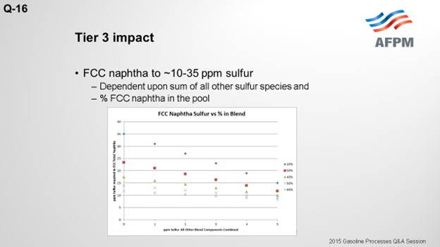
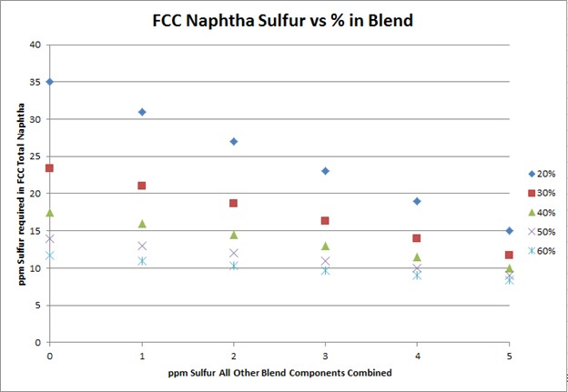
To meet Tier 3 10 ppm sulfur in the gasoline pool, FCC naphtha will need to be treated to 10 to 35 ppm. The target FCC naphtha sulfur level is based on the sum of all the other sulfur species in the pool, as well as the percent of FCC naphtha in the pool, as indicated in the plot.
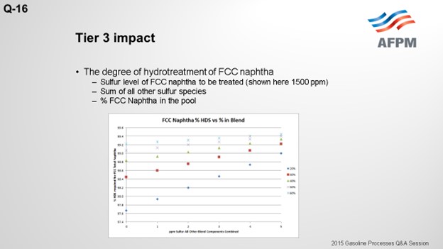
The degree of desulfurization of the naphtha is a function of the sulfur content of the FCC naphtha, the sum of all the other sulfur species, and the percent of FCC naphtha in the gasoline pool. The key takeaway from these two slides is that the lower the sulfur you can get all the other blend components, the less hydrotreatment the FCC naphtha will require and the octane loss you will experience. In any scenario, FCC light naphtha sulfur will need to be reduced. Adding a mercaptan removal unit can provide some octane preservation benefits due to reduced olefin saturation, but there are some risks.
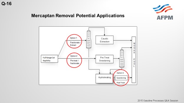
The drawing on the next slide shows three potential applications for mercaptan removal units in conjunction with a gasoline selective hydrotreater. The first option splits the light and heavy naphtha and sends the light naphtha to the mercaptan extraction unit. The cutpoint of the light naphtha needs to be adjusted to avoid thiophene into the extraction unit feed because thiophenes are not extractable and will increase the extracted naphtha sulfur. The light naphtha will recover all of the C5 olefins and some of the C6 olefins, but some of the C6 olefins will end up in the heavy naphtha and be sent to the hydrotreating reactor
This first configuration option results in a much smaller unit overall, which is less costly. The mercaptans from the extraction unit are typically between 5 and 10 ppm, but the total sulfur content may be a little higher than that due to the disulfide re-entry loses. But as Daryl indicated, there are ways to minimize the re-entry loses with a naphtha wash, for example. The risk with this configuration is an unstable naphtha splitter operation or upstream operation that results in thiophenes in the light naphtha. In this scenario, the sulfur content of the light naphtha will increase, which will require a deeper desulfurization in the heavy naphtha hydrotreating; and hence, higher octane loss.
The second configuration option sweetens the full-range naphtha by converting the mercaptans to disulfides. The disulfides are then recovered in the bottom of the naphtha splitter, and the heavy naphtha is fed to the hydrotreater. Now the light naphtha from the naphtha splitter in this configuration has very low sulfur, 5 to maybe 10 ppm of mercaptans, and that should be consistent. The cutpoint in the tower, again, should be adjusted to avoid thiophenes in the light naphtha to keep the sulfur level low. This configuration is more costly, and a much larger unit is required because the full-range FCC naphtha is treated. The risk associated with this configuration is the potential for caustic carryover. Sodium could end up in the naphtha splitter, which could lead to tray fouling or condenser fouling issues. Also, sodium could potentially end up in the gasoline hydrotreater feed and poison the catalyst there.
The third configuration option is a sweetening unit on the backend of the hydrotreating unit. This option does not reduce the sulfur content, but it does allow you to meet the doctor sweet test by converting any mercaptans that have been recombined in the hydrotreating unit.
BURTON (Motiva Enterprises LLC)
We are not considering any of these options with our Tier 3 units. However, I do have a comment on the option of installing a sweetening unit downstream of a hydrotreater. This is a configuration that one of our units previously installed and operated. We did not sufficiently understand the interaction between the two units, which lead to a significant product quality event. Upsets in the upstream naphtha stabilizer in the hydrotreater adversely impacted the sweetening unit resulting in off-spec gasoline. Because of this bad experience, we are not interested in considering similar options in the future. However, we do know of other refineries that have successfully implemented similar configurations. The key to success is fully understanding the interactions between the two units and providing adequate safeguards to ensure that upstream upsets do not create bigger problems in the downstream unit.
FRY (Delek Refining Ltd)
I will just add that we do not use a mercaptan removal process. We use selective hydrogenation (SHU) with a splitter on our FCC gasoline. The SHU will shift all of the sulfurs down into a heavier sulfur, which we will then hydrotreat. We maintain very low octane loss by using that type of process.
SCOTT LAMBIE (KBC Advanced Technologies, Inc.)
To meet Tier 3 gasoline sulfur specifications of 10 ppmw (parts per million by weight), the full-range FCC naphtha (C5 at 430°F) will need to contain anywhere from 10 to 35 ppm sulfur. The exact sulfur content of the FCC naphtha product differs for each refinery but is basically a function of two factors: the percentage of FCC naphtha in the gasoline pool and the total ppm sulfur in the rest of the other blend components combined. The following graph depicts the total FCC naphtha sulfur requirement for varying percentages of the total pool and sulfur in all other components combined. Note: The graph assumes the refinery gasoline product meets 7 to 8 ppm specification for potential pipeline contamination margin.
The degree of hydrotreatment of FCC naphtha is dependent upon several factors, including the sulfur content of the feed to be treated, relative amount of FCC naphtha in the pool, and combined sulfur of all other blend components.
Using a base FCC total naphtha sulfur level of 1500 ppmw, the follow plot depicts the degree of desulfurization required for varying percentages of the FCC total naphtha in the gasoline pool and sulfur in all other components combined.
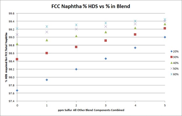
The plot above shows that the lower the sulfur of the blend components other than FCC naphtha, the lower the extent of hydrodesulfurization required for the FCC naphtha.
Treating the full-range naphtha stream to a low ppm sulfur level results in high octane loss, in large part, due to saturation of olefins. Many existing configurations for treating FCC naphtha split light and heavy naphtha and treat the streams to varying degrees to meet the desired product sulfur targets while attempting to minimize octane loss.
In the Tier 3 environment, light naphtha will require greater sulfur removal to meet the combined FCC naphtha total sulfur requirements. Heavy naphtha desulfurization rates will increase, as well, but only incrementally as desulfurization levels are already high to meet Tier 2 specifications and increased light naphtha desulfurization requirements.
Mercaptan removal units, in conjunction with gasoline selective hydrotreaters, in the Tier 3 environment, do very little to affect the overall desulfurization required in the heavy naphtha. For example, the impact of removing the mercaptans is estimated to reduce the heavy naphtha desulfurization requirements by approximately 0.1 to 0.5% depending on the sulfur level of the FCC full-range naphtha treated. The bigger incentive to adding a mercaptan removal unit in conjunction with a gasoline selective hydrotreater comes from reduced octane loss.
In Option 1 above, a naphtha splitter separates light naphtha from heavy naphtha. Light naphtha is sent to the mercaptan extraction unit while heavy naphtha is deeply desulfurized in the hydrotreating unit. Since only the light mercaptans are extractable, the cutpoint needs to be adjusted to prevent thiophenes from entering the extraction section as they are not extractable with caustic and would result in higher sulfur in the product. The resulting cutpoint recovers some of the C6 olefins in the heavy naphtha stream, and some octane loss of these components is unavoidable as they are treated in the hydrotreating unit.
The light naphtha mercaptans are extracted to less than 5 to 10 ppm, but the total sulfur can vary from 10 to 50 ppm depending on the operation of the unit and degree of disulfide oil re-entry losses to light naphtha. Extreme care must be taken to minimize re-entry losses of disulfides. Use of wash oils to minimize disulfide re-entry losses is a common practice. The sulfur level of the heavy naphtha product will need to be controlled to meet final sulfur levels. If very low FCC naphtha sulfur levels are required in the pool, due to the reasons mentioned above, the light naphtha total sulfur must be below 20 to 30 ppm in order for the heavy naphtha hydrotreating unit to be able to meet the final blend requirements. Naphtha splitter upsets resulting in high thiophenes to the extraction unit will be difficult to manage in the gasoline pool.
The benefit of the Option 1 configuration is reduced capital cost, due to the relatively low flow rate of light naphtha versus total naphtha, as well as some octane preservation.
In Option 2 above, the full-range naphtha is sweetened to reduce the mercaptan content. The boiling point of the disulfide oil produced is greater than light naphtha. As in Option 1, the cutpoint of the light naphtha is set to recover thiophenes to the naphtha splitter bottoms. The total sulfur of the heavy naphtha increases, but the degree and severity of the hydrotreating unit is essentially unaffected by the disulfide oil and more dependent on the removal of difficult sulfur species such as benzothiophene.
Option 2 results in a light naphtha stream that contains 5 to 10 ppm mercaptans and essentially no other sulfur species. Similar to Option 1, some of the C6 olefins are recovered to heavy naphtha and routed to the hydrotreating unit where they will lose some octane. The low-sulfur light naphtha allows for a higher heavy naphtha product sulfur. As a result, there is less of an octane loss across the hydrotreating unit with this configuration versus Option 1.
There are a few potential risks with the Option 2 configuration such as caustic carryover, disulfide decomposition, and possibly peroxide formation. Caustic carryover is not usually a problem; but if the unit experiences an upset, caustic can enter the fractionator. This could lead to fouling the trays and overhead condensers and possibly result in sodium going to the hydrotreating reactor, potentially poisoning the catalyst. At high temperatures in the naphtha splitter bottoms section, disulfides may decompose to form hydrogen sulfide that ends up in the overhead system and potentially corrodes the overhead condenser and equipment, if not designed to handle it. Regenerated caustic may contain dissolved oxygen that may react with olefins to produce peroxides. In the fractionator, the peroxides may react with olefins to form polymers. The polymers may foul up heat exchange surfaces such as the reboiler, condenser, and downstream hydrotreating unit.
The benefit of Option 2 is a consistent low-sulfur light naphtha product and slightly less overall octane loss than Option 1. The cost of the sweetening unit is higher than Option 1 because the entire FCC naphtha stream is being sweetened.
Option 3 post-treats the desulfurized heavy naphtha stream to remove mercaptans formed as a result of mercaptan recombination. While the tendency to form mercaptans is fairly low for heavy naphtha hydrotreating, the increase in C6 olefins as feed to the HDS unit increases the risk of mercaptan recombination reactions occurring. The mercaptans formed are not easily extracted, so the best way to convert the mercaptans and meet the doctor test is to sweeten them. Sweetening the mercaptans will not reduce the overall sulfur. If the overall sulfur is greater than 10 to 30 ppm, alternative means to reduce the overall product sulfur are required.
Option 3 is mainly an alternative to post-treating options and provides no octane benefit or desulfurization improvement. Its main function is to ensure that the product meets the doctor test. Mercaptan removal in this location will be hard to justify versus post-treating reactors.
Question 17: What considerations should you make when contemplating changing catalyst supplier from the original unit licensor?
LAMBIE (KBC Advanced Technologies, Inc.)
Changing catalyst suppliers is not an uncommon practice. It is done successfully in many different locations. Typically, cost and yield improvements are the most influential factors. However, there are some other key considerations before making the change. As far as the yields, it is important to review the catalyst’s performance data, particularly of operating units, if at all possible. Also, consider the commercial experience: How many units are operating out there, and how well are those units performing? In some instances, it may be necessary to review pilot plant data in the scenario where you are considering installing a newly developed catalyst.
From a cost standpoint, we need to look at the overall catalyst replacement costs. Many times, that includes the precious metals’ ownership or leasing arrangements that might be required, as well as any royalties from the original licensor and the new licensor. It is important to compare and contrast different quotes from multiple catalyst suppliers, if possible, which provides competition and helps drive down the costs. It is important to look at the total offering provided for each supplier, such as the startup and post-startup support, as well as any guarantees that the licensors are going to provide, such as any yield performance catalyst life or run length and/or any product specification guarantees.
One should look at the risks involved with changing the catalyst and have a backup plan in case it is not successful. Consideration of differences in procedures – whether operating, regeneration, or emergency – is important as well. It is also valuable to review any environmental or special handling requirements for the new catalyst. Almost as important as the cost and yields is the operator's knowledge and experience of his existing unit. Being familiar with all of the equipment, processes, and procedures is critical to ensure smooth transition from one catalyst to the next.
When considering changing catalyst, a refiner should be prepared for little or no support. This is not to say that there will not be any support; only that it may be limited, and refiners should be prepared for that. There are instances, as in the case of a CCR unit where there is proprietary equipment, when the new licensor will not be allowed to see that equipment and may not be able to support you. Similarly, an old licensor may stop supporting if a new catalyst is put in your unit. Having confidence in the unit operating staff to be able to adjust to the operation with a new catalyst will aid in the decision-making process.
DUNHAM (UOP LLC, A Honeywell Company)
Scott covered the question well with his answer. I want to add that this is a particular issue for the CCR because you are moving around catalyst. So, changing the catalyst can impact how it moves. You know the catalyst property. You know the size distribution and density. Everything will have something to do with that.
It becomes a sensitive issue if you start to have problems with the unit. You may go to the licensor and ask, “Why are we not getting the performance we want?” They will come back and say, “Well, I cannot tell you because you have someone else’s catalyst in here. We think it is a catalyst problem.” So sometimes you get fingers pointing back and forth: “Well, it is the process.” “No, it is the catalyst.” The issue then becomes what is acceptable to discuss; because the catalyst guy cannot look at your drawings and see what the equipment looks like, and the equipment people cannot look at your catalyst analysis. So, it really does go back to whether your organization can fill these support roles that you may be lacking if you go away from the licensor’s catalyst.
RATHINA SABAPATHI [(Kuwait National Petroleum Company (KNPC)]
Our issue is specifically with regard to continuous catalyst regeneration. The cause originated from the CCR. We have a concern about how the regeneration will be done for the other catalysts with regard to regeneration temperature. Also, at what temperature will the agglomeration of the platinum happen? We do not have much knowledge about these issues, which we need in case we go to another catalyst vendor. Can you throw some light on that?
WARREN LETZSCH (Technip USA)
I would not buy a catalyst from someone if he could not tell me how to regenerate it in the unit in which it is being put. In other words, the supplier should be able to answer your questions if he has done all of the testing on the catalyst and is familiar with your operation. If he cannot answer questions like that and give you the support, I would be reluctant, if you will, to go ahead and buy that catalyst. But maybe someone else has a different opinion.
RATHINA SABAPATHI [Kuwait National Petroleum Company (KNPC)]
The source of this issue is that this regenerator is property specific to UOP, and we have an issue handing over those documents to them.
DUNHAM (UOP LLC, A Honeywell Company)
Well, you can run into a conflict here where UOP has specific procedures for regenerating the catalyst and operating limits associated with that process. There are temperature limits, and others limits such as chloride and oxygen, when you are doing regeneration. Now if your new catalyst vendor is saying, “These are my procedures,” and they conflict with the UOP procedures, then you may end up with some equipment damage. So you have to decide what you are going to do because we cannot help you. [Laughter]
SHRIKANT MADHAV VAIDYA (Indian Oil Corporation Limited)
Recently, we had the experience of operating both kinds of CCR units. Our policy is that we do not limit ourselves to the licensor’s catalyst alone. We have been getting decent service from whichever supplier sold us the catalyst. Before we decide to switch the catalyst or evaluate the option of both suppliers, the NDA (Non-Disclosure Agreement) is signed between the licensor and prospective supplier of the catalyst, and they must agree to provide all kinds of technical support. We have no problem with this arrangement.
SANJIV SINGH (Indian Oil Corporation Limited)
I do not have a question. I have an experience to share about another petrochemical unit of Indian Oil. We wanted to change out the catalyst. The new supplier is able to guarantee the yields’ ex reactor, but he is not guaranteeing the final product for use. He says, “The downstream of the reactor consisting of purification section is not designed by me.” Hence, by virtue of the lack of guarantee of the final product purity, we cannot buy a new catalyst from a different vendor that is not guaranteed; so, we are stuck with the original licensor catalyst.
DANIEL THOMAS (UOP LLC, A Honeywell Company)
I have a specific example of the conflicts and problems of troubleshooting when you have a license from one party and a catalyst from another. This is just reinforcing the statement that was made earlier. If you are comfortable troubleshooting your own unit completely, end-to-end, you will have a lot more flexibility than a refiner who does not have the experience to be able to troubleshoot the entire unit. If you have one technology licensor and a different catalyst vendor, the licensor cannot look at the operating data from the catalyst; so he cannot help you troubleshoot effectively. The catalyst vendor does not know the technical data or many of the limitations from the mechanical design, so he will also have difficulty doing troubleshooting. If you can troubleshoot your own unit end-to-end, then you will be fine. But if you do not have confidence to do that, it will be very, very difficult to troubleshoot a problem and determine the exact cause.
DUNHAM (UOP LLC, A Honeywell Company)
Going back to one other question: Have we ever signed agreements where we share information with someone else’s catalyst fire?
DANIEL THOMAS (UOP LLC, A Honeywell Company)
To the best of my knowledge, no. Each catalyst vendor considers its own yield structure, densities, and information as proprietary and is very loath to share that with a competitor.
SCOTT LAMBIE (KBC Advanced Technologies, Inc.)
Changing catalyst suppliers from the original unit licensor requires a refiner to consider all implications. Typically, cost and/or yield improvements are the most influential factors affecting the decision to change catalysts. However, there are a several other factors that should be considered before making the change.
When evaluating yields, it is important to look at catalyst performance data, particularly of commercially operating units. When commercial data is not available, pilot plant data can be acceptable if the data is comparable to licensor reported commercial units. Refiners must evaluate the total offering from the alternate catalyst supplier(s). The offering should include the guarantees of the catalyst regarding the yield performance, catalyst life, and product specifications.
Differences in operating procedures should be reviewed, particularly regeneration for both semi-regenerative and CCR reformers, as well as water/chloride balance requirements. A review of emergency shutdown procedures required for the new catalyst, as well as any environmental or special handling concerns, should be evaluated.
The catalyst replacement cost should be competitive with the original licensor’s offering and have sufficient yield improvement to justify the change. The replacement costs should consider the ownership and/or lease arrangement costs of any precious metals. Royalties that may be imposed by the new licensor, as well as the original licensor, should be included in the analysis. When possible, compare multiple vendors to provide competition to help drive down costs. Refiners need to consider the risks of making the catalyst change and have a backup plan in case the catalyst change is not successful. A warrantee or guarantee helps alleviate this concern; but oftentimes, licensors are somewhat limited in catalyst change scenarios.
A very critical factor to consider before changing catalysts is the experience and knowledge of the refinery operating staff with regard to the operation of the unit and all of the process equipment, both externally and internally. When changing catalyst suppliers, particularly with CCR units, there are usually restrictions as to what the new catalyst supplier can see within the unit battery limits. Typically, the original licensor considers the equipment in the unit proprietary; and therefore, new catalyst suppliers are not allowed to enter the unit to offer assistance in troubleshooting if problems arise. New catalyst suppliers may attend the startup of the unit with the new catalyst but, in some cases, have limited access to information. The original licensor, in some instances, may stop support of the existing equipment and not offer to provide technical support when issues arise after the catalyst change to another supplier.
Having a strong operating staff knowledgeable of the process and all of the hardware and with the ability to provide the unit operation troubleshooting if/when issues arise is almost as important as the cost and yield improvement of the new catalyst. Operations’ knowledge and experience will ensure a smooth transition to operating with a new catalyst with minimal feedback or assistance from either the new or existing catalyst licensor. Many refiners have changed catalyst from the original licensor with success.
Question 18: Due to lower product octane requirements, has your strategy for dumping and screening fixed-bed reforming catalyst changed from the standard recommendation of three years or three in-situ regenerations?
PATEL (Valero Energy Corporation)
As with any catalyst, the deactivation rate is a function of processing similarity; and consequently, if the unit is targeting lower octane values, regeneration requirement can become less frequent. It is really up to the refiner to make the decision as to whether or not to let the cycle extend out longer because of the lower production of the coke or to regenerate more proactively on an annual basis to ensure that the yield losses are maintained at a minimum. Regenerating more frequently can also ensure that engineers and Operations people are trained in the regen procedures and that the unit is ready for gasoline mode.
Regardless, it is important to monitor the burn profile during the regen as this will be the true indicator of whether the catalyst needs to be dumped and screened. If a unit is coming up on a regen and has not been dumped and screened for a few years, then it is also good practice to dump and screen. The dump and screen scope should be planned for in advance so that the equipment onsite is ready. In case one is needed, it can be done. Then the catalyst should be a dump-and-screen if a maldistribution is observed during the carbon bone step, like ΔT (delta T; temperature differential) or high reactor ΔP (delta P; pressure differential). Conducting a dump-and-screen based on the regeneration cycle is a more preferred way over the dumping and screening based on a time of the service, especially for the operating board where the octane requirements are low.
DUNHAM (UOP LLC, A Honeywell Company)
Yes, I think the assumption here is that regeneration is the more severe operation; that is, when you are generating fines. So if you regenerate less often, you will not need to dump and screen. But there are other factors that could come into play. During the normal run, there may be reasons why you are building up pressure drop, deteriorating the catalyst, or laying coke, trash, or fines down on the catalyst. So I do not think that just regeneration cycle or time can be used to make this decision.
JIM PROROCK (Husky Energy Line)
In our fixed-bed reformers, we monitor the bed profiles and watch for when the ΔT (delta T; temperature differential) is not occurring on a reactor. When the top of the bed dies and the ΔT profile on the reactor is not complete, you see it exit the bed. So no, we used to do it on a timed basis, but now we monitor the reaction and make a choice based on that kind of a performance.