
Question 38: What measurements and criteria do you use to decide when to change your gas and liquid chloride absorber material? How do you determine the selection of absorber material?
John Clower (Chevron)
For both gas and liquid service, Chevron monitors the inlet HCL/Total Chloride and replaces the adsorbent/molecular sieve based on material balance loading of chloride on the adsorber media. Chevron does monitor adsorbent outlet HCL/Total Chlorides, but as a best practice will change the adsorbent material before vendor maximum loading if breakthrough has not occurred. Spent adsorbent will become acidic and pass chloride as organic chloride to the downstream processes. Organic chlorides are difficult to detect by conventional tubes in gas service and will form HCL in downstream processing units.
This performance-based approach is not without problems, e.g., the accuracy of both chloride measurements and represented adsorbent capacity, and therefore requires a trial-and-error
approach.
Represented capacity of any chloride trap material will have been set the vendor to minimize high acidity conditions that lead to organic chloride and polymer (red/green oil) production. Commercially there are four main types of chloride adsorbent material available:
•Alumina
•Modified/Promoted Alumina
•Molecular Sieve
•Metal Oxide
Each of these materials is used in Chevron Refineries and joint ventures. Each adsorbent type will have various properties that can be used in making a decision on application:
•Total chloride capacity (HCL and Organic)
•Reactivity – potential for organic chloride and red/green oil formation
•Interferences (e.g., Sulfur)
•Cost per pound of chloride removed
Also, the design of the vessel used is important (L/D for adequate flow distribution, contact time) and can result in shorten life versus predicted breakthrough. Selection of adsorbent versus service will usually be made on a cost per pound of chloride removed.
Janel Ruby (Johnson Matthey Catalysts)
Chloride can be removed from streams using various products. These chloride guard products can differ in the way they are manufactured and in the way they work in certain applications, so it is important to choose the right one for your needs. The most common products are chemical absorbents or promoted alumina adsorbents. Chemical absorbents remove chlorides by irreversible chemical reaction, meaning that the chloride is chemically bound within the absorbent. Chloride removal in promoted alumina is accomplished mainly by adsorption in which hydrogen chloride is adsorbed onto the alumina surface. Both types of beds are non-regenerable and require change-out at chloride breakthrough.
When determining which product is right for a particular service, it is important to evaluate the operating parameters of the chloride guard bed. The location of the bed in the reforming flow sheet, the operating temperature of the bed, and the normal and maximum inlet chloride levels are important factors to consider when selecting an absorbent type.
Promoted alumina products are available for liquid and gas services. Promoted alumina can work over a range of operating temperatures but chlorides that are adsorbed onto the material may desorb at higher temperatures which will decrease the effectiveness of the product in these regimes. These products also have a lower chloride capacity usually ranging from 12 to 15% wt/wt, and require a high change-out frequency. An area of concern when utilizing promoted alumina materials is the formation of undesirable side products. When the chloride binds to the alumina surface of the guard material, it creates surface acid sites. The acidic surface of the material can catalyze side reactions and lead to the creation of organic chlorides or high-molecular weight hydrocarbons called “green oils.” Green-oils not only foul equipment, but also the guard bed itself, which can cause difficulties in bed discharge (increased purge time) and disposal.
Chemical absorbents are the most favorable option for chloride removal. These products are available for use in liquid and gas services. Chemical absorbents work over a wide range of temperatures. These products have high chloride pick-ups, for example PURASPECJM 2250 is a mixed metal oxide chemical absorbent which can achieve a chloride capacity of 30% wt/wt in non-fouling, gas phase applications. As previously stated, these products remove chloride through an irreversible chemical reaction. The alumina structure present in these types of chemical absorbents acts only as a binder which minimizes the tendency for unwanted side reactions. PURASPECJM 2250 can commonly be employed with the use of just a single guard bed.
There a few other considerations surrounding chloride guard bed materials. It is important to avoid two-phase flow in these beds as this will affect the performance of the chloride guard. Both promoted alumina products and chemical absorbents have a higher pick-up in gas phase, non-fouling and non-wetting applications. In liquid applications, diffusion through the liquid film around the chloride guard particle is the rate limiting step and capacities are generally lower than gas phase duties because of the mass transfer effects. Chemical absorbent products, PURASPECJM 6250 and PURASPECJM 6255 were designed to address this concern. These products have a high capacity and specific pore structure to allow improved removal capacity. They are comprised of the same chemical formulation and micromeritic properties but represent two differing particle sizes; PURASPECJM6255 is manufactured as a smaller sized sphere. The smaller size provides better performance as this minimizes the liquid film through which the HCl must diffuse, reducing the depth of the mass transfer zone and leads to higher average chloride pick at the point of HCl breakthrough.
The presence of HCl or organo-chlorides (RCl) in the exit stream of the chloride guard bed will indicate it is time to change out the material. The life of the guard depends on how the bed(s) is configured and what type of product(s) has been installed. Unless the bed needs to be shut down for inspection or is involved in a larger turnaround plan, chloride breakthrough will be the main reason for a shutdown to replace product. Regular testing for chlorides in the exit stream will help to determine when change out is needed. In applications with longer life cycles (years) testing may only be needed monthly until the bed is getting closer to its expected change-out interval. In applications with shorter life expectancies (months), the frequency of testing should be at least weekly.
Throughout the life of the bed, it is important to measure the HCl and RCl levels both inlet and exit the chloride guard beds. It has been shown that when promoted alumina is used for HCl removal, it catalyses the conversion of HCl to organic chloride species that can then slip from the bed. If the operator is only measuring for HCl then this chloride slip can go undetected until downstream issues occur. Chlorides passing through the bed can cause corrosion of downstream equipment and formation of ammonium chloride that cause fouling and blocking of equipment e.g., stabilizer columns, exchangers and compressors.
Year
2010
Process
Question 39: With lower severity requirements due to ethanol blending and corresponding reduced coke make in the reformer, what changes are you making in regards to reformer operation? What opportunities does this evolution present for both CCR and semi-regen units?
John Clower (Chevron)
Increased ethanol blending has reduced the severity of the reformers on average 2 octane numbers. This has increased reformate yield and decreased hydrogen production. Although the octane boost realized by ethanol blending reduces overall pool octane requirements, minimum reformer severity may be dictated by octane requirements of premium gasoline grades, or by refinery hydrogen requirements. Therefore, hydrotreated naphtha blending into conventional grades may be required to reduce pool octane length.
The net effect on semi-regenerative operation is longer cycle life, and generally positive for those operations, especially where the reformer is the sole source of hydrogen supply. The only downside would result from the NHT cycle (from fouling of the combined feed exchanger or reactor bed differential pressure) setting the regeneration schedule.
The effect of low severity on CCR operation is more problematic. This topic was discussed fully at the 2009 Q&A session, Reformer Question #23.
The opportunities presented by lower severity, with respect to CCR operations, are related to increasing the severity of the CCR and maintaining the asset full utilized. They include:
•Aromatics production
•Shut down of existing semi-regeneration units at the same facility
Greg Harbison (Marathon Petroleum) The main issue with the low octane operation is the idling of the regenerator and in some cases near continuous operation of the regenerator in black burn mode. The sum effect is low activity catalyst and, hence, poor unit productivity for hydrogen and reformate yields. Where practical, Marathon has used process variable manipulation such as lowering the unit pressure, using lower H2/HC molar ratios, and increasing feed endpoint where necessary to maintain spent catalyst coke levels adequate for continuous CCR regenerator operation. In addition, where feasible we have block operated our units on high and low octane runs to permit operating the regenerator in white burn to maintain catalyst activity. These measures have allowed us to keep the regenerator operating and maintain catalyst activity.
Other suggestions that have been offered include one by UOP to modify regenerator operation to permit low coke CCR catalyst regeneration. Another idea that could be explored is the use of high boiling hydrocarbons to increase catalyst coke and permit more stable white burn regenerator operation.
In the case of fixed bed semi-regen type units, low severity operation would increase cycle lengths and time between catalyst regenerations and catalyst life. Matching up catalyst regenerations or changeouts with naphtha Hydrotreater cleanouts will require additional planning compared to historical planning.
For refineries that are hydrogen limited, the options for avoiding octane giveaway are few. Decreasing hydrogen consumption in the downstream units, recovering additional hydrogen from purge and fuel gases, operating at lower unit pressure, or increasing hydrogen production from a hydrogen plant are some of the options available.
Year
2010
Process
Question 40: Has anyone experienced high chloride levels in off gases from the lock hopper of a pressurized regenerator? What are the consequences of the high levels (i.e. fouled burner tips)? What are ways to mitigate the problem?
Greg Harbison (Marathon Petroleum)
Marathon has not experienced any high hydrogen chloride concentrations in Lock Hopper off gases from the two CycleMax regenerators that we operate. We have also not experienced problems with fouled burner tips due to high hydrogen chloride in the fuel gas to a heater.
We recover as much hydrogen as feasible from the Lock Hopper off gas. We route the Lock Hopper off gas to the net gas separation section of the Platformer, recovering most of the hydrogen. Thus, only a small portion of the off gas is routed to the fuel gas stream, and the resultant hydrogen chloride concentration in the combined fuel gas stream is low. In our units, this has not led to any burner tip fouling. We believe this to be a key factor in avoiding problems in the downstream fuel gas system.
Our first Cyclemax unit is a revamped semi-regen stacked reactor system that was originally intended to be a CCR Platformer at our Detroit refinery. This unit been in operation for over 5 years and there have been no fouling issues with heater burner tips. Our second unit is a CycleMax on Marathon’s latest Platformer in Garyville. This unit has operated for less than 9 months, and there have been no issues with high HCl in the Lock Hopper off gas. The HCl concentrations in the net gas and booster gas to the Lock Hopper are usually in the 2 to 4 ppm range. The combination of low HCl and the recovery of most of the Lock Hopper hydrogen in the separation (recontacting) system have not caused Marathon problems with burner tip fouling.
We also use a chloride guard bed on the net gas hydrogen stream leaving the unit to remove HCl and minimize the potential for downstream chloride related fouling. Overall, as in the case of burner tip fouling, Marathon has had no experience with fouling in other equipment due to high hydrogen chloride content in the Lock Hopper off gas in our pressurized regenerator systems.
We find that maintaining any HCl in the vapor phase is beneficial to preventing fouling. Insulating and/or heat tracing fuel gas lines will help minimize the impact of HCl related fouling in the fuel gas system. Using a source of hydrogen chloride free gas to the Lock Hopper would be helpful as well.
Although not specifically queried, our atmospheric CCR units do not experience burner tip fouling from the lock hopper vent gases either. This stream enters the heater directly with its own nozzle, not into the fuel gas system at the unit.
John Clower (Chevron)
Lock hopper off gas from a pressurized style regeneration system is hydrogen produced in the reactor section. The net hydrogen takeoff from the reactor section to the regeneration section may come upstream or downstream of the net hydrogen chloride treater. If corrosion or fouling issues exists in the regeneration hydrogen section, a refiner should consider moving the net hydrogen takeoff downstream of the chloride treater.
The function of lock hopper gas is to facilitate the changing operating pressure at the lock hopper from regeneration tower pressure to reactor 1 pressure.
The hydrogen off gas from the lock hopper will either be directed back to the separator or to the fuel gas system. This gas may contain as much as 1+ ppm chloride (depending on lock hopper conditions and hydrogen source) and some catalyst dust.
High chlorides in the fuel gas can cause fouling of mesh blankets in knock out drums, and corrosion of SS burner tips leading to cracks.
If the lock hopper of gas is the source of fouling or corrosion, mitigations include:
•Route the hydrogen off gas away from the fuel gas system, incurring the cost of compression but recovering a hydrogen rich stream •Adding a chloride guard bed to the lock hopper gas that passes to the fuel gas system
Year
2010
Process
Question 41: Do you have any experience with plugging of chloriding agent injection points in regenerators? How has this been overcome?
John Clower (Chevron)
The chloride injection line has a nitrogen purge connected with the intent to sweep the chloride into the chlorination gas line. In most designs, the nitrogen and organic chloride line join together before the chloride on/off valve. When the chloride valve closes, both chloride and nitrogen sweep are stopped.
The chloride in the line between chloride valve and chlorination gas line will heat up and sometimes form a heavy viscous semi solid at the junction between organic chloride injection line and chlorination gas line.
To mitigate this problem, first ensure that the injection line between chloride valve and injection point is free draining in the direction of the chlorination gas line. Also, relocate the nitrogen purge downstream of the chloride valve so that there is always a continuous nitrogen sweep and the injection line remains free of liquid.
Later generation pressurized regeneration systems do include a permanent nitrogen sweep downstream of the chloride on/off valve.
Greg Harbison (Marathon Petroleum)
Marathon has had a recent case of plugging of a perchloroethylene chloriding (PERC) agent in the injection line to the chlorination zone. Ammonium salts were identified as the plugging material. One key data point was identifying that the PERC in use for this unit contained 97 % of PERC or tetrachloro ethylene and about 3 % contaminants including water, isobutyl alcohol, trinitro-chloromethane, amines, and others. We are still unclear if it was an isolated case which could have been caused by a number of factors including the design of the PERC injection system, PERC grade type that could have contained contaminants, or intermittent operation of the regenerator between idling and black/white burn operations. The PERC in use at some of the other Marathon refineries is compatible for use in Isom units. Those refineries have not experienced chloride plugging in the injection system. They also utilize a nitrogen carrier when in white burn operations, an injection quill, and the chloride agent typically enters the top of the pipe, so it is free draining.
We also operate an Ultraformer swing reactor unit at our Robinson, Ill. Refinery. This unit operates a regeneration system at 250 psig and has had intermittent problems with chloride injection quill pluggage. We have significant flexibility with this unit and shut down the regen system to unplug the quill when necessary. This unit does not have a nitrogen purge, nor is the chloride piping blown out when not in use.
Year
2010
Submitter
Process
Question 46: What is the panel's experience with in-line blending and in-line certification? What are the main differences between in-line blending and certification?
Greg Harbison (Marathon Petroleum)
For clarity, a common definition of “in-line blending” is required. Marathon defines in-line blending as a system that pumps multiple blend components from individual tanks, which are typically “live” (either receiving or capable of receiving components from a process unit or pipeline delivery) into a header. The header generally contains static mixing to ensure homogeneity of the blend. The header is lined up to a finished product, or “certification” tank. Often, property analyzers are used to adjust the blend recipe as the blend is being made. Some of the more common analyzers used are octane (engine or NIR), RVP, sulfur, and distillation. Computer control schemes can be configured to adjust the blend recipes, based on the analyzer readings and target values for given properties. Manual adjustments to the blend recipes can also be made by gasoline blending operators, if computer control is not available. It is common to have routine check samples sent to the refinery control laboratory to both verify the on-line analyzer results and also compare the blend results to the expected values from the blend recipes. The final tank blend is subsequently certified by the refinery control lab. Marathon has in-line blenders at many of our refineries.
In contrast, blending can be completed in a batch-wise manner (sometimes referred to as “splash”-blending), by pumping pre-determined volumes of individual components into a tank, and then circulating the entire tank prior to certification testing. On occasion, Marathon utilizes a variation of this approach when “re-blending” a tank to correct an off-spec result.
In-line certification occurs when blending analyzer results are used rather than laboratory results to characterize the finished product. This process presumes adequate mixing in the blend header, a homogenous blend in the tank, and applies the aggregate results of the blend (typically through an integrative computer control scheme) to the entire batch. Without in-line blending, in-line certification is not possible, although in-line blending is possible without in-line certification. To certify a blend in-line using an analyzer, a rigorous statistical comparison of in-line versus laboratory results is required to prove a strong correlation between results. Federal regulations (40 CFR) contain a list of which properties may be certified in-line and define the requirements for demonstrating compliance with applicable specifications. Road octane (AKI) is generally regulated by individual states, not by the federal EPA, and doesn’t fall under the jurisdiction of 40 CFR. The states typically have adopted some version of ASTM D4814 for octane testing. To in-line certify octane via analyzers, pipeline carriers / customers must approve the alternate test method, generally with the same burden-of-proof (strong correlation between analyzer and laboratory results) for the refineries. With any in-line certification process, a program to routinely verify analyzer results is necessary. Marathon has developed corporate guidelines for the use of on-line analyzers in certification testing.
In-line certification can be used on individual properties alone, which then requires laboratory testing for the remaining properties, or it can be used for all properties of the blend, potentially allowing “live” exports from the blend header to a product pipeline. Several Marathon refineries in-line certify some properties of the finished blends. Marathon does not live blend to product pipelines.
In-line blending can have several advantages to batch-wise blending:
•As mentioned, if coupled with in-line certification for all properties, it provides the opportunity to blend directly to a pipeline, which in turn would reduce finished tankage requirements for the refinery. This can reduce a refinery’s working capital load, by not having to carry as many tank bottoms levels.
•There is much tighter precision / less specification give-away on the blend properties, as the computer control schemes quickly and easily adjust the blend recipes in real-time.
•On-line analyzers used for in-line blending can help detect changes in component make-up / properties, via shifts in the aggregate properties of the blend, allowing for larger-scale recipe adjustments to correct for the changes.
•Blending and certification times can be reduced, as the blends are generally on-spec the first time, and do not require re-blends. There are, of course, some inherent risks associated with in-line blending and certification:
•When shipping “live,” analyzer malfunctions / failures can result in releasing off-spec product.
•If not shipping “live,” minor analyzer malfunctions / shifts may result in unexpected re-blending requirements. For example, in a batch blending operation, it is possible that sufficient “cushion” was built into the blend recipes to allow for changes in the component make-up. However, with analyzers automatically adjusting blend recipes to drive closer to a spec limit (e.g., RVP), it is possible that a blend which was thought to have finished on-spec actually comes back off-spec. Then, re-testing and/or re-blending may be necessary, which may result in shipment delays and additional cost.
John Clower (Chevron)
At the Richmond Refinery, we blend gasoline in-line from multiple component tanks to a finished product tank. The tail line, finished gasoline, product has multiple analyzers that are monitored by operations continuously.
F1 and F2 are monitored by engine analyzers and are certified by the state for on-line tank release, allowing for zero “giveaway” on octane.
Five separate analyzers exist for RVP, aromatics (including benzene), olefins, sulfur, and distillation. These non-certification analyzers are confirmed by the lab twice per shift. The product tank final must include laboratory analysis of these five components.
Year
2010
Process
Question 47: What are the best practices for corrosion probe selection, installation and reliability, especially in high temperature and/or high H2S environments?
Alec Klinghoffer (Coffeyville Resources)
Some things to consider when selecting and installing corrosion probes are to match the metallurgy of the probe to the pipe. Also, it is very important to try and determine where the corrosion is actually occurring on the pipe when installing the corrosion probe. This is important because the probe is a “point” measurement and corrosion can take place in the vicinity of the probe without the probe actually measuring it. The probe depth should also be taken into consideration because one wants to measure on the edge/ID of the pipe and not somewhere in the middle of the pipe.
In high temperature, high H2S environments, it is important to match metallurgy and packing material. Typically, for normal applications, the packing is made out of Teflon. This cannot be used in high temperature applications so care must be taken to ensure a suitable packing material is used. In addition, metallurgy is a consideration in high temperature applications. It is best to use Hastelloy is high temperature, highly corrosive environments.
The probes need to be reliable as the data needs to be “long term”. Since corrosion is a slow process, data needs to be collected over a 5 – 6-month period to get an accurate representation of corrosion rates.
John Clower (Chevron)
Recommended techniques for corrosion monitoring include the use of electric resistance probes and AUT (automated ultrasonic testing).
ER probes can be ordered with some consideration for the process environment and are available in retrievable, retractable, fixed, and flanged mountings. They are rated up to 6000 psig and 850 °F.
AUT is transducer mounted externally, and thus suitable for any process environment. AUT corrosion mapping has many advantages over internal corrosion probes or external UT monitoring:
•High sensitivity corrosion detection
•Quantitative thickness measurements
•Faster results versus manual UT
•Repeatable
•No welding required
•Ease of interpretation
Sam Lordo (Nalco Company)
Corrosion probe selection is based on the velocity, metallurgy and the operating conditions of the system to be monitored. They are very effective when properly installed and maintained.
Year
2010
Process
Question 48: In your experience, what is the preferred online (non-destructive) method to identify risk of HIC (hydrogen induced cracking) in gasoline processing units?
Alec Klinghoffer (Coffeyville Resources)
The preferred method of identifying the risk of hydrogen induced cracking is to measure the permeation or flux of hydrogen on the outside surface of the equipment and correlate this to the corrosion rate on the inside of the pipe. There are several manufacturers of this type of equipment where a probe is attached with straps or a magnet and the flux of H2 is measured at the pipe surface. The small, portable equipment is equipped with a highly sensitive H2 analyzer. The sensor registers the concentration of H2 in the air stream. Since H2 is highly diffusible in air, the background level of H2 is usually low and stable and therefore the increase in H2 in the air stream is a dependable way of measuring hydrogen at the surface. The apparatus uses correlations to determine the corrosion rate on the inside of the pipe or vessel. The advantages of these analyzers are that they are portable and dependable, the work for temperatures up to 1100F, are intrinsically safe, collect data in “real time” and are reliable. Fixed monitors are also available. Typically, these types of analyzers collect data in a small amount of time and can calculate corrosion measurements in minutes.
Greg Harbison (Marathon Petroleum)
If the expected damage mechanism could result in hydrogen blistering, hydrogen induced cracking (HIC), or stress-oriented hydrogen induced cracking (SOHIC) our experience has shown that automated ultrasonic (AUT) scan is the most beneficial in identifying, mapping, and sizing the damage to pressure vessel walls. In some instances, we have utilized portable hydrogen permeation probes as a precursor inspection to identify areas of high diffusible hydrogen activity to prioritize the AUT inspections.
John Clower (Chevron)
Shear wave may be used for external measurement of HIC but will not always find existing problems. If HIC is suspected, the best practice for detection would be an internal inspection using surface eddy current.
Paul Fearnside (Nalco Company) In gasoline processing units analyzing for any cyanide related corrosion byproducts (Prussian Blue) would be recommended. If found the first step would be to make sure the upstream units, i.e., FCCU and/or Coker, gascon water washes are performing up to industry best practices to reduce/eliminate the corrosives that generate the monatomic hydrogen responsible for the HIC. Once that has been done, then specialized filming amines and metal passivators have been used successfully to control the HIC potential.
Year
2010
Process
Question 49: What testing procedures do you use for emergency shutdown valves? What are the parameters you measure and what are acceptable values?
Jim Johnson (Marathon Petroleum)
The appropriate required testing of emergency shutdown valves is included in each Marathon refinery’s Mechanical Integrity (MI) program, complying with OSHA’s Process Safety Management regulation and EPA’s Risk Management Plan regulation. Inspection, testing, and preventive maintenance (ITPM) plans are detailed for each equipment class, which includes Emergency Isolation Valves (EIV’s), emergency shutdown valves associated with Emergency Shutdown Devices (ESD’s) pre-ANSI/ISA S84.00.01, and Safety Instrumented Systems (SIS’s) as defined by ANSI/ISA S84.00.01.
The minimum ITPM tasks for EIV’s include a full stroke test, verification of DCS/HMI alarms, position indication, valve closure, and internal valve inspection. The testing will only be done off-line and include a full test of the driver. If the EIV is in a location that can be isolated on the run the valve will be tested bi-annually, except for the internal valve inspection which is only done during turnarounds. If the valve cannot be isolated on the run, all testing will be completed during turnarounds. Limit switches must be satisfied that the valve travels fully open and closed. The internal valve inspections are to be conducted by a qualified inspector and if internal damage is observed an appropriate repair plan will be developed which may include leak testing after repairs.
Emergency shutdown valves associated with ESD’s are to undergo a full functional test on an annual basis if the ESD was designed for on-line testing or will be tested during turnarounds if not designed for on-line testing.
Valves associated with SIS’s undergo testing detailed in the individual Safety Requirement Specification (SRS). An example of a notable additional requirement for SIS’s is that heater shutdown valves (Class 6) are leak tested with the leak rate measured in bubbles per minute that must pass the leak test tolerance in accordance with ANSI B16.104-1976. These valves are leak tested on either a 5-year interval if available on-line, or the turnaround interval if not. We no longer perform partial functional tests on shutdown valves, only full tests.
Frank Tracy (ConocoPhillips)
ConocoPhillips have developed guidelines for emergency shutdown valve testing. The default frequency for testing emergency shutdown valves is one turnaround cycle. Testing frequency may be increased based on experience in a particular service or as necessary to achieve the safety integrity level (SIL) required by a layers of protection analysis (LOPA). For shutdown valves that require testing between turnarounds, a bypass must be provided.
Testing includes:
-Leak test the plug / seat in as found condition
-Disassembly, inspection, repair of valve and actuator
-Reassembly and testing of valve and actuator including a final leak test the plug / seat
Year
2010
Process
Question 42: In your experience, what are the typical causes of damage to the top of the regenerator inner screen?
John Clower (Chevron)
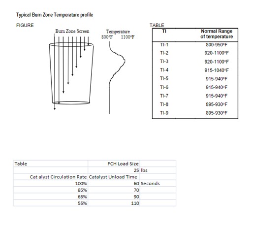
The typical cause for damage in the top 2-3 ft of inner screen is metal fatigue due to thermal cycling.This is common to all CCR designs, but more critical in early pressurized designs. Catalyst entering the regenerator from the vessel above is relatively cool, from the catalyst lift and elutriation. The cold catalyst enters the regenerator and the regeneration gas at the top of the screen will cool as it passes through this top section of catalyst, then in turn the gas will cool the inner screen.
As the carbon burn begins, catalyst temperature will increase thereby causing the inner screen temperature to rise. Each time catalyst cycles, a thermal cycle at the top of the regenerator inner screen will occur.
The thermal cycle can also occur if oxygen control is fluctuating significantly but in this case the damage will not be confined to the top section of inner screen.
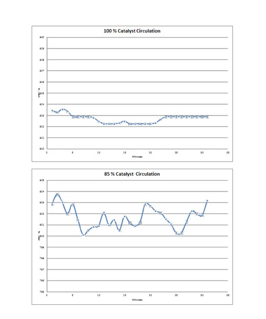
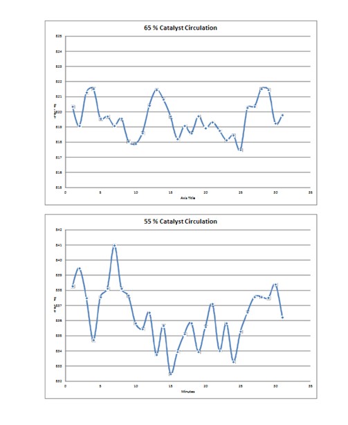
Catalyst circulation rate plays a part in the amplitude of the temperature cycle at the top of the inner screen. Lower catalyst circulation rates lead to larger cycles and increased fatigue. The same is true for shutdowns that occur during normal operation at any catalyst circulation rate.
The increased amplitude of the thermal cycle at lower rates can be problematic for CCR units operating at lower reactor severity. Consideration should be given to metal fatigue when determining how to operate in a low coke make regime.
Year
2010
Process