Moderator: Don Ostman
Question 61: In your experience, what is the effect of crude oil compatibility on crude unit preheat exchanger fouling? Are there any correlations used to predict fouling?
Doug Meyne (Champion)
Since there are only isolated instances of fouling in the “cold train” exchangers prior to the desalter(s), we will assume this question is directed more towards the “hot train” exchangers.
First, it needs to be understood that inorganics can provide a “substrate” for organic material to bind to and accelerate agglomeration. At higher temperatures, inorganics can also add a mild catalytic effect to condensation, i.e., dehydrogenation. If deposits show >10% ash, it’s an indication that inorganics may be playing more than a simple passive role. Better removal of solids at the desalter can have a strong impact on preheat fouling, to the extent of virtually eliminating it all together. That being said, an otherwise compatible blend could still foul the preheat train if the desalter isn’t doing a good enough job removing solids.
For the most part, preheat fouling is caused by asphaltene precipitation. At lower temperatures the asphaltene isn’t prone to stick (adsorb) onto equipment surfaces as long as sufficient velocity (>~5 fps) is maintained. A significant amount of literature and research suggests that asphaltene precipitation increases with temperature up to a limit, and then the asphaltene precipitation decreases. Although this temperature varies from unit to unit and with different crude blends, it usually happens in the 400 Deg F range. As the oil heats up, asphaltenes that have fallen out of solution can be resolubilized, but the time it takes them to go back into solution is longer than the preheat time. When encountering hot tubes, the asphaltenes become tacky and will adsorb onto them.
Some crudes can be considered to be “self-incompatible” in a crude unit if they can precipitate asphaltenes by themselves. This situation is rare but can happen. One of the concerns coming out of Canada today is the lack of a good standard for the diluents used in a DilBit. Lighter aliphatic diluents (C7-) at % levels are known to precipitate asphaltenes, but as the weight of the aliphatic increases, so does solubility of the asphaltene. However, in the preheat train as the temperature rises and the density of the diluent decreases, there could be some non-linear effect that could aggravate precipitation. Under this circumstance, this would be a “self-incompatible” crude. Diluent variability can make this hard to diagnose.
The “Dead” oils used in refining, those that have had oilfield gases removed, aren’t as susceptible to pressure variation as “live oils” that will “flash” oilfield gases at a pressure drop. This reduction in pressure and increase in gas is known to cause asphaltene precipitation in production. With insufficient backpressure on a hot oil in a crude preheat, an otherwise stable oil could experience a similar effect in the hotter exchangers. This would then also be a considered a “self-incompatible” crude.
One indication of the precipitation potential of asphaltenes is to run standard SARA (Saturates, Aromatics, Resins, and Asphaltenes) testing on each crude slate. As a rule of thumb, higher aromatics and resins decrease asphaltene precipitation and higher saturates and asphaltenes increase asphaltene precipitation.
There is not agreement in the industry as to the effect of temperature on asphaltene solubility. Some data suggests the solubility is improved with higher temperature, whereas other data suggests higher temperature causes the stabilizing resins to be pulled away from the asphaltenes. Regardless, if an asphaltene precipitates at some lower temperature but doesn’t adsorb onto a tube surface, and if it could resolubilize into the oil, the time necessary to go back into solution is longer than the residence time available in a preheat. Inevitably the insoluble asphaltenes will adsorb (stick) onto hot tubes. Once that happens, at the higher temperatures, the asphaltenes and any still-associated resins will begin the process of dehydrogenating to coke, which cannot be resolubilized.
Different types of flocculation tests can be done, using varying ratios of heptane/toluene to provide a relative scale for the precipitation potential for any given sample of crude oil or crude oil blend. Similarly, the same tests can be used on blends of various crude oils. Since one crude oil may have a low asphaltene and resin content, and another may be rich in resins but with a different asphaltene structure, size and morphology, interpolating their values to determine the potential for fouling can’t be done linearly. However, Irwin Wiehe with Soluble Solutions out of Gladstone, NJ, has published, with some authority, a procedure for testing individual crudes and predicting the precipitation potential of their blends.
Jim Johnson (Marathon Petroleum)
One of our refineries has experienced serious problems with oil and solids undercarry while processing bitumen crudes along with some asphalt destabilization due to mixing lighter paraffinic crudes with very heavy crudes. Increased fouling was observed in the pre-heat circuit during these episodes, however due to the effect on the wastewater treatment plant we were not able to assess the contribution of crude compatibility to the observed fouling. Efforts were concentrated on attacking the effect on the desalter operation. Marathon is a member of the Canadian Crude Quality Technical Association and through that group we understand that there are no correlations currently available that reliably predict fouling. The CCQTA is currently embarking on a project to better assess crude compatibility and one of the deliverables is to develop a fouling correlation.
Sarah Jacob
William Wilkins, PhD
Question 53: During the coking cycle, how are drum skin temperatures used to monitor drum wall condition?
Frank Tracy (ConocoPhillips)
Monitoring drum wall conditions during the drum cycle is best performed using strain gauges. Each strain gauge location will typically be fitted with gauges in both the axial and hoop directions and have an associated skin thermocouple. These can be seen in the photograph.
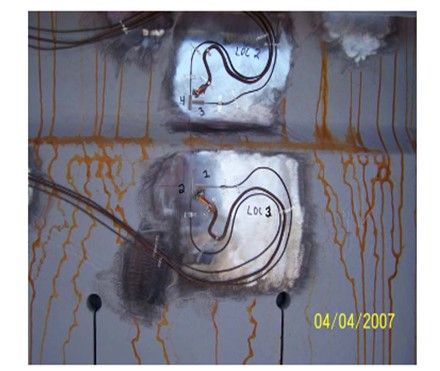
The largest stresses typically occur during the water quench portion of the drum cycle. Strain gauges allow a refiner to minimize stresses during this critical portion of the drum cycle by adjusting quench water rates. However, this is a longer-term project as you must evaluate enough cycles to have representative data for evaluation before making an operating change and then collect enough data afterwards to make a meaningful comparison.
Selecting the locations for strain gauge installation is something that requires some careful consideration. Strain gauges can be retrofit onto existing drums and are recommended as part of new coke drum installations. Typically, it is only necessary to fit strain gauges on one drum in each set of identical drums receiving the same feed since all drums will behave similarly.
Skin temperatures alone do not provide the same information as strain gauges. They can be used to help ensuring adequate back warm. They may be useful, if strategically deployed, to possibly identify uneven quenches.
We have used or are currently using strain gauges at several of our cokers and plan to use them at some additional locations.
Eric Thraen (Flint Hills Resources)
We have conducted several coke drum stress studies using outside consultants. Coke drum skin temperatures and strain gauges are included in the stress studies. The strain gauges are used primarily for these engineering studies, while the temperature indicators are used by the operating personnel, along with quench water flowrates and coke drum pressure rate of change during the drum cooling step to manage the rate of cooling so as to meet the targeted coke drum lifecycle. Quench water flow and coke drum pressure are included in the coke drum cooling program as added checks to ensure against too rapid quenching during the cooling cycle. The minimum coke drum preheat prior to switching feed into a drum is based on strain studies by the outside consultants. Although the stresses during water-cooling are generally highest, a minimum drum preheat is also established to prevent excessive stresses during the drum heating cycle.
Eberhard Lucke (Commonwealth E&C)
Drum skin temperatures are mainly monitored in the critical areas around the drum skirt attachments and the first 1-2 circumferential welds from the bottom in the cylindrical portion of the drum. The data from these skin temperature elements can be used in the DCS to monitor the change in temperature over time during the critical stages of the drum cycle, the drum quench and the drum warm-up/switch. Keeping the dT/dt in a certain range will minimize the thermal stress on welds and drum wall and will increase the lifetime of the coke drums. These dt/dt values can be integrated into the control scheme for the quench water ramp function, the warm-up controls and the drum switch control, depending on the degree of automation you have in your unit.
Question 54: What is the current best practice for number of feed nozzles, angle, and location on coke drums considering the use of slide valves for the bottom unheading device?
Frank Tracy (ConocoPhillips)
There is not a one-size-fits-all answer to this question. However, we believe that an arrangement that closely matches the conventional bottom center upflow arrangement will provide more uniform thermal stresses on the drum and minimize operational impact.
Within ConocoPhillips we have multiple cokers that have retrofitted valve-type unheading devices onto bottom heads and use single side feed entry. These drums have not had any significant operational or mechanical issues resulting from the retrofits to date. We also have one coker, which still has manual bottom unheading, that has had dual side entry for more than fifty years. We have one new coker that is in construction that will utilize dual side feed entry.
One ConocoPhillips Coking Technology Licensee installed valve-type unheading with single-side entry. Upon converting to single side entry, they experienced significant temperature gradients in the drum resulting in drum deflection and a permanent “banana” shape as well as an increase in blow outs. They are converting to dual side entry and early reports are that this has improved their operation back to where they were with original bottom center upflow arrangement.
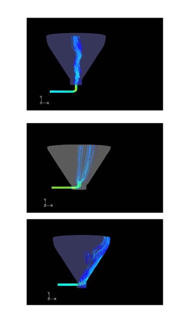
Because there are so many factors to consider; including feed properties, operating conditions, and drum geometry; we are using CFD modeling to aid in assessing the number, location, and entry angle for feed nozzle(s). CFD modeling in this application is still a work in progress for us, but we believe it is a useful tool. In some cases,
the additional complexity and cost of dual-side feed entry is warranted while in others it is not.
The next three CFD model snapshots illustrate: 1) bottom dead center feed, 2) single side entry for a case where single side entry might be selected, and 3) a case where single side entry as configured might not be recommended. These are different drums with different feeds, conditions, and geometries. ConocoPhillips have CFD modeled several variations around single vs. dual side entry, location of feed, and entry angle.
For dual-side entry there must also be a reliable piping system that is designed to support the nozzle configuration.
ConocoPhillips have licensed four retrofits to dual feed nozzle systems and can provide Licensing assistance in this area.
Finally, DeltaValve have a prototype for a retractable feed device that attempts to simulate bottom dead center feed entry. This is reported to be going into trial sometime in the fall of 2010.
Jim Johnson (Marathon Petroleum)
It is our understanding that industry is leaning toward dual feed nozzles at a 45-degree angle to the bottom cone when installing slide valves. Marathon’s refineries have nine drums with single side entry and have no issues. We did not see our hot drum occurrence increase when we converted from a bottom entry to a side entry when installing the slide valves.
Eberhard Lucke (Commonwealth E&C)
I have seen no major problems with the single inlet nozzle on the side of the drum cone, if designed properly. I also haven’t seen any significant advantage in using multiple feed points around the cone. The single feed injection point should be angled slightly upwards. I like the concept of going back to the old “bottom inlet” flow pattern with the new slide valve designs. I would have to see that one in operation though before I would recommend it.