
Question 28: The Clean Air Act required refineries to develop and implement a Leak Detection and Repair (LDAR) program to control fugitive emissions. What is the current status of this implementation and who is responsible for it in a typical refinery management structure: production, maintenance or EHS?
Greg Harbison (Marathon Petroleum)
Background/Regulatory Requirements:
Since the inception of the Clean Air Act of 1955 and multiple amendments through 1990, Leak Detection and Repair or LDAR regulations have been a part of air pollution control. Today’s LDAR programs are governed by Federal and State regulations and agreed orders (consent decrees) that provide the control of fugitive emission leaks from process equipment by requiring equipment inspections and leaking equipment repair. As such, the specific requirements can vary company to company or even between refineries operating in different states within the same company. Marathon complies with these regulations.
Equipment Inspections
Components that are LDAR applicable can vary by type and inspection or monitoring frequency. Generally, LDAR components consist of valves, pumps and compressors that are monitored on a quarterly basis. Monitoring requirements can be more stringent for units built or modified post November 2006 and can apply to flanges, connectors, fittings, hatches, and agitators (to name a
few). Process stream speciation determines the applicable regulatory requirements for streams. The typical streams requiring the most rigorous application of LDAR regulations include:
1. gas/vapor streams that are typically > 10% ethane and heavier,
2. light liquid streams are typically heavy naphtha or kerosene depending on specific stream properties, and
3. process streams containing greater than 5% hazardous air pollutants (benzene, methanol, toluene, etc.)
These monitoring requirements can be more or less frequent and have different leak definitions based on different applicable regulations. A leak definition is the threshold in parts per million that a component must reach to be considered leaking. LDAR monitoring is outlined in EPA Method 21, which states that a toxic vapor analyzer (TVA) must be used to assess total volatile organic compound (VOC) leaks from LDAR components. As LDAR regulations become stricter, the leak definitions are increasingly being lowered. With every change in regulation, the LDAR program becomes more challenging to manage since most facilities are required to stay below a facility wide leak percentage for leaking equipment (typically 2%). Thus, a rigorous and well-structured leak repair and maintenance portion of the LDAR program is vital to minimize emissions and maintain compliance.
Program Oversight
A practical LDAR program encompasses multiple people spread across many different job functions. Overall, it is our experience that a successful LDAR program can be successfully managed if several critical items are in place. These include dedicated personnel, a robust software database, good overall management system, well defined roles and responsibilities, and a comprehensive auditing system. At our refineries, it is typically the responsibility of the facility Environmental LDAR Coordinator (HES Professional) to manage and oversee all aspects of the LDAR program. We also use a contract company to conduct the emissions monitoring, and another contract company to make the initial leak repairs on valves (typically injection of a sealant into the valve packing area). Other LDAR applicable components such as motor operated valves (MOV’s), control valves, pumps and compressors are repaired when leaking by qualified individuals within the facility Maintenance Department. The requirements for completing the repairs are often sensitive to equipment and process functionality.
The LDAR Coordinator should have daily communication with the LDAR Monitoring Contractor to go over every open leak Work Order. This information is reviewed and an updated list of all leaks within the facility is given to the Contractor and facility Maintenance Department every day.
Overall, the regulations are complex and can generate an overwhelming amount of information based on the size of the facility and how many leaks are found above the leak definition. A large refinery could have upwards of 70,000 LDAR components governed by state and federal regulations as well as additional requirements from agreed orders. It is imperative to have a functional LDAR database that manages this information. The database should be capable of scheduling all monitoring and repair dates based on applicable regulations for the facility. The progress of the monitoring schedule needs to be easily accessible for all parties involved.
Year
2010
Process
Question 29: What technologies do you use for treating or recovering VOCs from small-scale truck loading terminals? Discuss the merits associated with each?
Alec Klinghoffer (Coffeyville Resources)
The three main VOC treating systems for small scale truck loading are vapor combustion system, flare gas recovery unit, and an adsorption/absorption vapor recovery system.
The simplest system is the vapor combustion system. In this system, the vapors flow through a vapor shutdown valve and detonation arrestor and enter a combustor. The vapors are ignited by a pilot and the assist air blower provides some combustion air and mixing energy to ensure smokeless combustion. This system is very robust and provides very efficient combustion of the hydrocarbon vapors. It is also a very simple system mechanically so there is very little maintenance involved and is used in a lot of additional applications (such as wastewater installations).
The second type is the flare gas recovery unit. This unit consists of a knockout vessel, a liquid seal vessel and the flare itself. A flare header collects gases from various sources and as the flare header pressure reaches a set point, a liquid seal compressor starts up and begins to compress the gases. A heat exchanger is used to control the compressor discharge temperature. The compressor discharge is sent to a 3-phase separator that separates the liquid from the flare gas. This liquid is recovered and can be sold as product or used elsewhere in the refinery. The recovered fuel gas can be sent back to the refinery fuel gas system or processed as a chemical feedstock. The advantage of this system is the recovery of the gas and liquid to be re-used in the refinery. Also, there is a minimum amount of flaring since a portion of the gas can be used elsewhere in the refinery. The liquid recovery directly affects profits and minimal flaring is viewed as a better option from the point of environmental stewardship.
The third type of vapor recovery system is the adsorption/absorption vapor recovery system with a “dry” vacuum pump. This system is the most complex but probably also the most environmentally friendly system of the three presented here. The unit is equipped with 2 identical activated carbon filled adsorbers. One adsorber is always on steam while the other is being regenerated. When loading is occurring, the VRU automatically starts and sends hydrocarbon rich air to the activated carbon bed. The bed removes the hydrocarbon through adsorption and vents air with a minimal amount of hydrocarbon. During regeneration, the carbon bed is stripped of hydrocarbon using purge air and high vacuum. The purge air is discharge directly into an absorption column where the hydrocarbons are stripped from the air. The stripping medium in the absorber column is usually a material similar to what is being loaded at the rack (i.e., gasoline). In the absorber, the vapor is liquefied and returned back to the storage tank. A small stream of air and residual vapor is recycled back through the carbon bed for re-adsorption. The major benefit of this system is that most if not all of the hydrocarbons are recovered in this system. There is also an elimination of a flare in this system and there is reduced energy consumption because of the dry vacuum pump system. There is no compressor in this system so maintenance cost decrease and reliability increase for this configuration.
John Clower (Chevron)
Technologies used for VOC recovery are simple adsorption technologies or incineration. The technology used depends on design vapor load and emissions monitoring requirements. The Richmond Refinery employs a carbon adsorption/absorption vapor recovery system at its truck terminal. This system employs two carbon drums, one in adsorption mode and a second in regeneration or standby.
The “adsorption” flow path passes through a carbon vessel and past continuous emissions monitoring and to a vent.
The “regeneration” flow path uses high vacuum and air purge to remove adsorbed hydrocarbons from the carbon bed. The extracted hydrocarbons accumulate in a separator and are processed through an absorber for recovery of heavier hydrocarbons back to the storage tank.
Year
2010
Process
Question 30: What process parameters can affect alkylate T90? What are the critical variables you monitor in both sulfuric and HF units? Discuss processing schemes, feed impacts and operating variables.
Randy Peterson (STRATCO)
The type of feed is very significant for T90. Amylenes make alkylate with higher T90 in both sulfuric and HF units. Propylene generally makes lower T90 than butylene in HF units. However, with sulfuric-catalyzed technologies, propylene can increase T90 as discussed below. Diene contaminants (butadiene and pentadiene) also raise T90 for both catalysts since they form heavier alkylate. Selective hydrogenation units that remove dienes are therefore helpful in reducing T90.
In sulfuric alkylation, propylene reacted with butylene and especially amylene in the same reactor will lead to higher T90s than if they were alkylated separately. This is due to side reactions that produce heavier alkylate. Therefore, segregated feed systems where different olefins are fed to specific acid stages are beneficial. Normal olefins have lower T-90 and End Points relative to isoolefins. Thus, MTBE/TAME raffinate has lower T-90s than mixed butylenes/mixed amylenes.
For a given feed type in sulfuric alkylation, I/O ratio is the most critical process variable. The lower the I/O, the higher the T90. Low acid strengths also increase T90 so acid staging should be designed to minimize the fraction of alkylate produced at the lowest acid strength. For HF alkylation, low I/O ratio is also the most significant variable causing increased T90. Acid strengths above 90-92 wt% increase EP and T90 due to the higher activity of the catalyst and tendency for polymerization. Low acid strengths (below 87 wt%) also tend to increase T90 due to increased side reactions and increased acid carryover in the iso recycle. Excessive internal acid regeneration can raise EP/T90 as well.
Higher reactor feed nozzle ΔP and/or increased reaction zone mixing reduce T90 for both catalyst types.
John Clower (Chevron)
Alkylate T-90 can be affected by a number of different schemes, feeds, and operating variables within a Sulfuric Acid Alkylation plant. An increase in T90 signifies heavier, lower octane product, normally a result of polymer formation.
The critical operating variable to monitor for alkylate T90 is the isomer to olefin ratio. Polymerization becomes a favorable reaction at I:O ratios of less than 5:1. At these ratios, olefins can react with other olefins in the acid continuous emulsion. At Chevron we monitor alkylate endpoint to track polymerization as a check for reaction conditions.
Increased contactor temperatures can also increase polymerization, but likely would not increase T90 as the polymer would not be a large percentage of the total alkylate product.
Olefin feed segregation is one means of controlling alkylate quality and acid spending strengths. Segregation of C3 olefins allows for their operation at higher acid strength contactors. At Chevron we segregate C3/C4 olefins to high acid strength contactors and C4/C5 olefins to low acid strength contactors.
C3 olefins tend to make conjunct polymers at low acid strengths and will also form polymers with C5 olefins at low strengths. If a plant feeds less than 10% C5 olefins, an increase in that percentage will result in increased T90.
Greg Harbison (Marathon Petroleum)
Reaction temperature and isobutane to olefin (I/O) ratio are two of the most important variables we monitor for alkylate quality. Acid to hydrocarbon ratio is also an important variable and is routinely monitored for our UOP units which have a pumped acid design. For COP Units, this is not a variable that can be changed.
Year
2010
Process
Question 31: In your experience, when sampling the HF Alky iso-recycle stream, how and where is the sample neutralized prior to analysis? Can this approach be used for online GC analysis as well?
Randy Peterson (STRATCO)
The isobutane recycle sample can be neutralized at the sample location using a chamber filled with alumina or KOH pellets. If using a KOH chamber, it is best to add a filter downstream to filter out any fines.
Alternately, the sample may be neutralized in the lab upstream of the GC by the same method. In some refineries, KOH pellets have been added directly to sample bombs prior to sampling.
The iso recycle from the side draw of an isostripper typically contains about 1% HF. However, if the tower is refluxed and the iso recycle stream comes from the tower accumulator, the sample may contain more HF.
Greg Harbison (Marathon Petroleum) Marathon has six HFA’s. Some of our refineries neutralize the recycle isobutane lab sample with a cylinder containing solid KOH in the field at the sample station, and others complete the neutralization in the lab. Additional KOH is added to the cylinder at a predetermined timeframe via the use of a PM work order. We have not used this arrangement for on-line G.C.s. The reaction of HF with KOH will result in the formation of water. If this feed pretreatment were used for an on-line unit G.C., the water formed would create issues with the addition of a wet stream to an acidic environment. Localized corrosion at the return point to the process may occur.
Year
2010
Process
Question 32: In your experience, what contributes to Monel denickelification in the HF Acid Regenerator circuit? What are the potential problems associated with this?
Randy Peterson (STRATCO)
Oxygen is a major cause of monel denickelfication. Oxygen can enter the circuit during loading operations. Care should be taken to avoid pressuring air contained within loading pipes/hoses into the unit.
Whenever monel is overlaid on carbon steel, a “butter” layer of nickel should be laid down prior to the monel layer. This step reduces the potential of a poor quality overlay.
A corrosion problem has been reported with packed regenerators using monel rings. Due to distribution problems commonly associated with packing, portions of the packed beds run dry and hot. The monel tends to severely corrode under these conditions leaving only a copper residue.
Although packed regenerators typically work well when first commissioned, trayed regenerators tend to have less corrosion over time as the trays are kept cool by the flowing liquid. Therefore, fixed valve trays are recommended in this service.
Year
2010
Process

Question 33: How do refiners avoid De-isobutanizer (DIB) column/reboiler fouling in sulfuric acid alkylation? What process conditions on the column do you use to detect this fouling? What process modifications do you take to minimize the impact of this fouling?
Randy Peterson (STRATCO)
Fouling in the DIB column is almost always caused by salt deposits. These salts are typically sodium sulfate and sodium sulfite but can also contain calcium or magnesium if the effluent treating water is not demineralized. If these water-soluble salts are present in the DIB feed, the water will evaporate once inside the column leaving the solids behind. The salt deposits are typically found on or near the feed tray.
The long-term solution is to make changes to the effluent treating system. The quickest operational change is to increase the water makeup rate to the system to dilute the aqueous salt concentration. Monitor conductivity in the water effluent and maintain a level less than 5000 μmhos/cm (microSiemens/cm) to minimize salt carryover.
Properly designed and functioning water wash static mixers are very important to wash any salts out of the tower feed. A retrofit of coalescing media should be considered in all effluent treating vessels to minimize carryover of the salt-containing aqueous phase. If the unit does not have a water wash downstream of an alkaline water wash, a water wash coalescer with static mixer should be considered.
Improving the water quality with softer water can also help. However, it is important to note that some refiners have experienced foaming problems in their water washes when using water that is too soft. Mixing a little hard water with the demineralized (soft) water typically solves the problem (40-50 ppm total hardness in the makeup water is a good target).
A quick fix to improve DIB operations while running is to perform an online water wash. Although this carries some risks, several refiners have successfully restored column operations. The typical method is to add water to the column feed. In doing so, the salts fouling the feed tray are made soluble. The salts are then carried away from the feed tray and redeposited on nearby trays as the water evaporates. This is not a permanent solution as the salts typically remain in the column until washed properly off-line. It is best to add the water as close to the tower feed nozzle as possible to avoid stagnant pools of water in the feed line which can lead to corrosion in low points.
Reboiler Fouling
Reboiler fouling is almost always caused by ineffective effluent treating. If the reaction intermediate esters (typically propyl or butyl sulfates) are not decomposed within the treating system, they enter the DIB and travel down the tower. When they reach the hot reboiler, they thermally decompose releasing SO2 while the organic component fouls the reboiler tube bundle. An indication that this is happening is low pH and high iron in the DIB overhead accumulator water draw. The evolved SO2 and water forms corrosive sulfurous acid. A good target pH is 6.5 – 7.5 with less than 10 ppm iron.
To avoid reboiler fouling, an increase in the temperature of the effluent treating water wash temperatures (>120 F) may help break the esters down. Typically, new static mixers, designed specifically for immiscible fluids, are required.
Some refiners report success with online water washing of the reboiler. Either water is directly added to the reboiler hydrocarbon inlet or enough water is added to the feed so that water goes down the column to the reboiler. In many cases, the boiling water breaks up the foulant and sends it downstream. If not severely fouled, the reboiler performance is restored. Care should be taken with the resulting wash water as it will have low pH (1-2) and will contain solids. In severe cases, the tube bundle requires pulling and hydroblasting to mechanically remove the foulant.
John Clower (Chevron)
DIB fouling typically starts in the alkylation unit reaction section. As reaction conditions deteriorate with increased feed rates (higher contactor temperatures, lower I:O, higher OSV) the amount of side reactions increase.
One critical side reactant with respect to DIB fouling is neutral esters. Neutral ester removal occurs at the alkaline water wash upstream of the DIB.
Increased rates through the alkaline water wash can result in declining separation of the hydrocarbon and aqueous phases, and underperformance of the heat input in the treatment section – the outlet of the alkaline water wash must be maintained above 120 °F to decompose the neutral esters, as high as 150°F If feeding large amounts of C3 olefins. Left unchecked, these esters will decompose and foul either trays in the DIB or its reboiler.
To avoid DIB fouling where heat input is the limitation, the installation of a trim heater is appropriate. If the outlet temperature is above 120 °F and fouling still exists, a second treatment step can be added as a water coalescer downstream of the alkaline water wash. The coalescer uses fresh water to polish any dissolved solids carried from the alkaline water wash.
The column dP above the feed tray is the most immediate way to detect column fouling. This can identify fouling 6 months before column performance is negatively affected. Overall column dP may not indicate fouling with the upper trays become more loaded, and the lower trays become less loaded as salts plate out on the feed tray.
Increasing column pressure can prolong run length once fouling is detected at the expense of iC4 recovery from the DIB.
Mark Meterna (Sulzer Chemtech USA)
Distillation is essential to the alkylation unit, where efficiently working trays produce a high purity isobutane recycle stream to the reactors with minimum energy consumption. Trace sulphuric acid and acidic by-products from the alkylation reaction may cause corrosion of distillation internals and damage the capability of trays and heat exchangers.
It is easy to detect corrosion and fouling of the distillation internals and to prevent further corrosion by understanding the mechanism by which it occurs. Corrosion of these internals can be further minimized by effectively operating and monitoring the treating section directly before the distillation columns. The refiner should monitor Deisobutanizer reboiler duty, Deisobutanizer overhead accumulator water pH, and separation efficiency (overlap in product distillation). Trends in any of these items may indicate that adjustments are required to the operation of the treating section. The presence of iron in the overhead accumulator water is another indication that metal losses are occurring upstream as a result of corrosion.
The net effluent stream from the reactor section contains corrosive components such as trace free sulfuric acid, alkyl sulfates and di-alkyl sulfates. These alkyl sulfates, or esters, are reaction intermediates produced during the alkylation reaction and if not treated in the treating section will foul and corrode process equipment and distillation internals.
If the trace acid and esters are left untreated before entering the deisobutanizer, they not only cause corrosion, but the alkyl sulphates will produce solid, tar-like material in the bottom of the column and on the reboiler due to the high temperature. During the formation of the tars, SO2 is released and travels up the column to collect in the overhead system. In contact with water in the overhead, SO2 causes corrosion of the overhead system equipment and piping and also of the rectifying section distillation trays. This reduces the fractionation between isobutane and n-butane resulting in poor purity of the isobutane recycle stream to the reactors.
Another form of corrosion in the Deisobutanizer is caused by water carryover if the treating section is finished with a water treating or caustic vessel. If water or caustic is carried into the column, the feed tray can be fouled with salts which will deposit when the water evaporates.
Though there are various treating section configuration and designs, the main principles hold true for all; efficiently mix the treating agent with the net effluent to maximize the contact between the two fluids, and effectively settle the two fluids before the next process step. The net effluent stream from the reactor section contains corrosive components such as trace free sulphuric acid and reaction intermediates (esters, or alkyl sulphates and di-alkyl sulphates). With well-mixed effluent and treating fluid, the trace acid and esters can be neutralized and removed from the hydrocarbon stream. Both mixing and separation can be improved with static mixers such as Sulzer SMV static mixers which develop the optimal droplet size to improve the contact between the two fluids, while minimizing small droplets and creating the chance of an emulsion to form. An emulsion of the hydrocarbon stream and the treating fluid can be challenging to separate. Separator internals, such as Sulzer Mellaplate, can also be installed in the separator vessel to improve separation between the two fluids. Increased separation capability and efficiency reduce the risk of water or caustic carryover to the deisobutanizer and minimize the chance of corrosion and fouling. Sulzer VG AF™ Trays can also be used in the deisobutanizer to reduce the impact of fouling and accumulation on trays. Sulzer VG AF™ Trays are designed with large, fixed valves that allow vapor to still pass through the trays. They are also designed with push valve technology, which reduce accumulation on the tray deck in stagnant regions and use high performance downcomers to help reduce accumulation. Tailored design features make VG AF™ Trays less sensitive to plugging and increase the run time of fouling applications while delivering high capacity and efficiency.
Procedures for online water washes can be developed to wash away the fouling material on the lower trays as well as the tar on the reboiler but monitoring the unit and minimizing the water carryover from the treating section will help reduce the need for column water washes. Monitoring the amount of water in the overhead accumulator, and the pH and iron content of the water are good indicators of how the treating section is performing and will help reduce the amount of corrosion to the distillation equipment.
Year
2010
Process
Question 50: Chemical cleaning of towers and vessels prior to entry is being used to reduce time to entry. What practices are you employing and how much time is saved?
Eric Thraen (Flint Hills Resources)
Our chemical cleaning practices for Crude/Vacuum and Coking units have evolved over many years. The starting point in most cases, after feed is out and the unit has circulated down, cooled and pumped out, is a flush with diesel or LCO followed by a good steamout. A good steamout helps to eliminate residual oil adhering to metal surfaces and also helps eliminate pockets of oil trapped in piping low points. A good decommissioning closed piping and slop containment system is essential to ensure this residual oil is removed before beginning the subsequent chemical cleaning steps. In a small number of units, the decommissioning piping is a permanent facility but, in most cases, this decommissioning piping consists of temporary piping installed at grade level prior to shut down. A system of piping, pumps, and temporary cooling exchangers is needed along with the ability to route uncondensed hydrocarbon vapors and steam to the flare. Often this is integrated with the unit or area flare knockout, with the added ability to pump recovered oily steam condensate to closed temporary storage “frac” tanks. Care must be taken to segregate the recovered chemical cleaning condensate to prevent contamination of the sour water system and to prevent high chemical flowrate to Waste Water Treatment Plant. The chemical cleaning condensate is later processed through the refinery’s WWTP in a controlled manner staying within the WWTP’s load capabilities.
The decommissioning piping is also used in the chemical cleaning step that follows initial steamout. Generally, the lighter oil sections of fractionating towers and related piping and exchangers are vapor-phase cleaned, whereas the reduced crude and heavier sections are water (liquid) – phase cleaned. The liquid-phase cleaning is simpler to plan than the vapor phase cleaning but can produce larger amounts of wastewater to process. The vapor-phase cleaning also has the advantage of the higher temperatures employed during steaming. Without under-appreciating the value of the chemical cleaning agents, the extended steamout required for vapor-phase cleaning would in itself provide better oil and gas removal than the cleaning provided by simple short steamout decommissioning plans that were used many years ago.
The chemicals employed include detergents/degreasers to remove oil and degas equipment, followed by oxidizing agents (permanganate) to greatly reduce the potential for iron sulfide deposits smoldering when equipment is later opened.
The times required for chemical cleaning vary depending on the size of the equipment and the complexity of the piping systems involved. Care must be taken to not recontaminate parallel systems after they have been cleaned. Generously sized decommissioning piping and generously sized exchangers for condensing and recovering oily condensate are essential to ensure good equipment drainage. Failure to adequately drain condensate formed during vapor phase chemical cleaning can cause liquid barriers to collect in piping system low points including low points found at rack piping expansion loops, piping manifolds, exchanger piping and other piping low points. Preventing this liquid buildup will save much time trying to deinventory, again, large complex piping systems. The ability of the boiler house to provide adequate steam for vapor phase cleaning needs to be considered. Generally, the vapor/steam-phase cleaning will require sustained steamout rates approaching the peak rates used in simple steamouts.
Ralph Goodrich (KBC Advanced Technologies, Inc.)
KBC has a Reliability, Availability, and Maintenance (RAM) consulting group that provides among other services a Turnaround Optimization Program. This program and corresponding support services are designed to help clients in optimizing the various stages of turnaround preparation and execution activities. This includes the need to optimize a turnaround duration, part of which is equipment cleaning in preparation for vessel entry for inspection and maintenance work.
It is our belief that implementing a comprehensive chemical cleaning program using today’s “Best Practice” technology should be an integral part of ensuring a safe environment for workers while at the same time reducing the time for equipment cleaning prior to vessel entry. Current leading-edge technology includes vapor-phase chemical cleaning agents which can be injected through a steam source. Advantages of the vapor-phase application typically include faster clean-out times, less waste, and the ability to contact all surfaces. We have found that the proper application of state-of-the-art cleaning and decontamination chemicals can reduce the clean-out time significantly.
For example, our experience has shown that using latest chemical cleaning technology for crude units we can expect up to 2-3 days can be saved from more historical cleaning methods. A single large vessel such as a vacuum column or coker fractionator can typically see up to a 2-day savings. Also, since the unit is normally much cleaner compared to historical cleaning methods, the maintenance effort becomes more efficient as significant post cleaning is not necessary and the inspection and maintenance activities can start much quicker than when utilizing traditional cleaning practices.
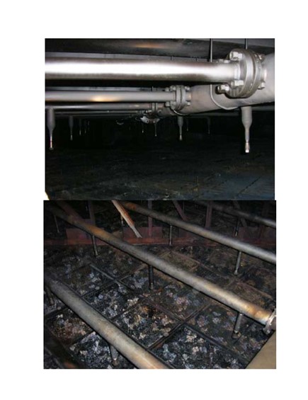
An example of how the improved cleanliness can make the maintenance easier and reduce costs is provided by a major refiner who recently decided to make a significant improvement in their vessel cleaning procedures. This included using a “new” vendor, whom they selected after an extensive evaluation process to improve their cleaning strategy and execution for a large vacuum column. Not only did they reduce the cleaning timeline by two days, but the resulting cleaning was also so complete they were able to cancel plans to replace the packing. The savings from that alone was worth over 3MM$ and saved two weeks of turnaround time. The two photographs at the end of the text indicate the post cleaning state of the column internals.
As a final point, we would recommend performing at least a short HAZOP or MOC review before conducting any new chemical cleaning procedure. It is also important to utilize an experienced vendor and to work closely with them throughout the entire process, from initial planning including modification of shutdown procedures to incorporate the nuances of the chemical cleaning process through final execution to help ensure a safe, successful, and on schedule equipment clean-out.
Jim Johnson (Marathon Petroleum)
Our decontamination procedures and practices have evolved over the years with the crude and vacuum units utilizing chemical cleaning to prepare the equipment for maintenance. One of our refineries has developed a practice that concentrates on flushing the residual oil from the system prior to addition of chemical resulting in a more effective chemical cleaning.
1.Rather than installing drain piping throughout the unit to tie into the slop system, all oil is water flushed to the crude or vacuum column where the water is subsequently drained to the sewer and the oil is pumped to the slop tanks utilizing the existing bottoms pumps.
2.The entire crude pre-heat and column side-draw circuits are water flushed to the column, with fire water connected to the appropriate pump suction. This provides a clean water flush rather than circulating oily water from the tower.
3.The chemical cleaning step follows the cold-water flush. On the crude unit water is circulated from the pre-flash tower through the heater and back to the pre-flash tower using the main fractionator bottoms pumps through the start-up circulation piping. The heater outlet is brought up to 250 degrees. Chemical is injected into each of the product draws and the water flush of each circuit is resumed. 4.After the water circulation, fresh water is used to flush the pre-heat exchanger circuit to the tower where the water with chemical and any recovered oil is pumped to storage to be processed through the WWTP later at a controlled rate.
5.As the side draw circuits have been water flushed, the water can be drained from all low points directly to the sewer without a detrimental effect to the WWTP.
6.The unit is then steamed out with steam introduced at the heater coils and at multiple locations on the column. The heater is re-lit with the outlet increased to 500 degrees for a final unit steam–out.
7.After verifying the unit is hydrocarbon free through ‘bomb tests and lab GC the tower is rinsed with cold water. An oxidizer is also used to reduce the potential for iron sulfide deposits to smolder.
Gregg McAteer (Nalco Company)
We are applying cleaning chemistry to towers and vessels and cutting normal steam-out time by approximately 2/3. The tower or vessel is then clean and saves further cleaning time so repairs can begin immediately.
Year
2010
Process
Question 51: In your experience, what are the implications on coker heater run length and coke drum operations with the following feedstock quality: Contaminants (Na, Ca), low saturates or high asphaltenes, crude compatibility, solvent deasphalt (SDA) pitch, low asphaltenes and high saturates?
Frank Tracy (ConocoPhillips)
I will first speak to the heater run length portion of the question and then to the coke drum operations portion of the question.
Heater Run Length
There are at least three main mechanisms under which the heater tubes become fouled:
•Inorganic material deposition or precipitation,
•Rapid asphaltene precipitation,
•Coke formation
All of these may contribute to chronic heater fouling. We link acute episodes of rapid fouling with the first two mechanisms.
1) We will begin with inorganic materials. Inorganic fouling more typically occurs in the upper radiant or even the lower convection section of the heater. These materials may be inherent in the crude or may be introduced during production, transportation or upstream processing of the oil prior to its arrival at the coker. Suspended solids in the oil are often a source of these inorganic materials.
The sodium and calcium noted in the question are certainly two that are common problems. 15-20 ppm sodium has long been the industry rule of thumb for a maximum limit for sodium in coke feed and one we use internally. Of course, we would like to see values below this range. Crude unit caustic injection for chloride control will contribute to the vacuum resid sodium load.
Silicon is an inorganic which has caused significant problems in at least three of our cokers. Silicon has been identified with certain crudes with the source most commonly being silicates and silica (quartz). Additionally, silicon-based anti-foam is suspected as a foulant in at least one case.
Iron is another inorganic we have seen cause heater tube fouling. Iron sulfides and other iron compounds enter with the crude and are not effectively removed in the desalter and end up in the feed to the coker.
There are other inorganics associated with fouling coker heater tubes and include aluminum and magnesium (associated with silicates) and barium. However, in our experience, these are less prevalent than the four previously mentioned.
Inorganic deposits often do not lend themselves to removal using online spalling or steam air decoking, and consequently, pigging must be used.
Ideally inorganic materials should be managed and minimized upstream of the coker. This may involve desalter operation, managing crude unit caustic injection, and addressing issues with crude suppliers. In addition, other streams fed to the coker such as FCC slurry oil and refinery slop oil can contain inorganic materials that may be detrimental to coker heater run length.
2) Asphaltene deposition is a second mechanism to watch for. We have experienced rapid, episodic fouling events due to asphaltene precipitation. This tends to occur in the upper radiant or lower convection section. It is sometimes linked to highly paraffinic resids or when the feed is a resid hydrocracker bottoms or deasphalter pitch stream.
Within COP we use asphaltene stability and proprietary coking propensity testing to evaluate feed stocks and identify and address problems with feeds or feed compatibility. ConocoPhillips proprietary Distillate Recycle technology, which recycles coker distillate through the furnace and coke drums, can also improve asphaltene stability.
3) Coke formation, the traditional heater tube fouling mechanism, is the third mechanism. The heaviest coke formation usually occurs in the lower radiant section where temperatures are the hottest. Turbulence and high velocity can be used to minimize the time any molecule is at the interface with the hot tube and are utilized to minimize coking. Velocity steam is used for this purpose. Distillate Recycle technology can also be used for this purpose, plus there is a yield benefit as well.
Drum Operations
Let’s shift to the second part of the question, which was how these factors effect drum operations.
Inorganic contaminants don’t have much impact on drum operations. However, for anode cokers, there could be coke quality implications with most of these contaminants.
Different feed stocks can have an impact on coke drum operation. The top of the coke bed has had the least amount of time to complete the coking reaction. If you have a less reactive feed stock, such as a hydrocracker bottoms stream, then that material in the top of the bed will be less converted to coke and more like tar than a traditional vac resid feed. This material is more likely to plug flow channels in the top of the bed and be less effectively quenched, which may result in more hot spots and blow outs.
We believe an increase in the amount of resid hydrocracker bottoms being fed to two of our cokers to be the reason for increased blowouts and have limited the amount of this material to help address this issue. We have also raised coke drum temperature to help complete the coking reaction.
Ralph Goodrich (KBC Advanced Technologies, Inc.)
With contaminates such as sodium and other salts the heater fouling is accelerated. This generally is related to a desalter upset or poor desalter operations. In extreme cases a desalter upset can cause the delayed coker to foul in a few days or less.
Caustic injection is a common practice to mitigate chloride corrosion problems in the crude tower and overhead system. However, the resulting sodium in coker feed can accelerate fouling in the delayed coker heater and should therefore be kept below 15 ppm. Thus, the caustic injection rates should be carefully monitored and kept to a minimum or eliminated if possible. Solids in the feed to the coker can also cause rapid fouling. For example, in some locations in Canada, the solids content is as high as 2 wt%. These extreme levels of solids will tend to cause fouling in the coker heater (the upper radiant and lower convection sections), fouling in the coke drum overhead vapor line, and main fractionator flash zone section.
High asphaltenes in the feed will also increase the furnace fouling rate. Furthermore, the high asphaltene content will tend to produce a shot coke, which in turn can cause drum cooling problems and high drum thermal stresses, ultimately resulting in drum cracks. Finally, there are definitely crude compatibility issues to be aware of. Dissimilar crude and resulting coker feeds can result in difficulties in drum cooling and hot spots - foaming can be an issue as well. Some of these problems with dissimilar coker feeds can be addressed with procedural changes but at some point, limiting the offending crude is the only economic choice. In general, to avoid these problems, keep the feeds to coker as similar as possible, i.e., do not mix highly asphaltenic feeds with highly paraffinic feeds.
Year
2010
Process