Question 19: What range of sulfur targets for hydrotreated FCC gasoline do you anticipate for Tier 3 operation?
JEFF BRAY (Honeywell UOP)
The sulfur target for hydrotreated FCC gasoline is very site dependent. But where possible, it is desirable to hydrotreat all other gasoline streams fully so that the FCC naphtha can be treated as mildly as possible. Deeper desulfurization for FCC naphtha results in increased olefin saturation with the resultant octane loss. Since the other gasoline streams can be hydrotreated without this reduction in stream value, hydrotreating of FCC naphtha should be done to the lowest level possible.
Within the structure of the Tier 3 rules, the flexibility to manage the yearly average sulfur provides some flexibility for operating the FCC hydrotreating at a constant degree of desulfurization needed to drive the yearly average to 10 ppm while also ensuring that the batch limit of 80 ppm is met. In practicality, it is probably better to target a sulfur level, as long as the conditions required to achieve that do not become too severe. Target levels will vary depending on the amount of FCC naphtha in gasoline and the sulfur levels of other blend streams, but these sulfur levels are expected to be in the range of 15to 35 pp.
The reduction of the sulfur target can require different strategies for the hydrotreating of the FCC streams. Many sites separate the lighter, higher olefin FCC gasoline from the heavier, more aromatic cut. The heavier cut goes through a more intensive hydrotreating, while the lighter stream is either blended or processed with technologies like extractive Merox™ treating to avoid olefin saturation. This treatment may not be sufficient to meet Tier 3specifications in all cases. If not, further processing of the light material will be required, resulting in more olefin saturation. This saturation, in turn, may drive the need for higher octane generation in other gasoline streamsto replace the octane loss from FCC naphtha hydrotreating.
Year
2016
Process
Question 21: What programs or systems do you employ to monitor hydrotreater furnaces and prevent tube failures and loss of containment? Can you share your experiences using technologies to implement online temperature monitoring of tube skin temperatures?
JEFFREY MUELLER (Marathon Petroleum Company)
In nearly all hydroprocessing heaters, MPC has installed tubeskin thermocouples in order to provide continuous monitoring of tube metal temperatures to the DCS (distributed control system) operator. These thermocouples are strategically located in the heater at the areas with the highest estimated maximum heat flux. For most heaters that operate at lower firebox temperatures, the welded-on type of thermocouple has been fairly reliable for the turnaround cycle. In this installation, the thermocouple is designed to wrap around the tube, with the end welded to the hot side of tube. The wiring to the transmitter is ran on the back side of the tube and typically out the heater can, where the transmitter is located. MPC has experienced much lower reliability with the retractable thermocouples (not welded directly to the tube).
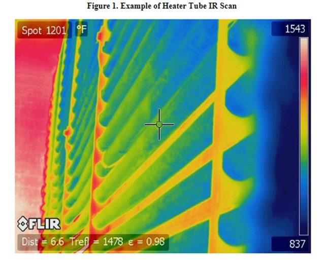
While tubeskin thermocouples provide continuous monitoring, it is important to remember that they are representative of only one point in the heater. On a periodic basis, which varies based on heater service and history, MPC inspection will take an IR camera shot of the heater tubes to look for any localized hot spots (see Figure 1).
NHT Heaters
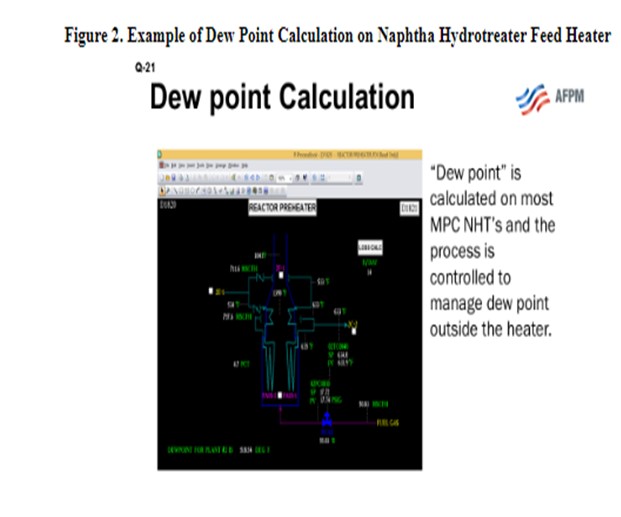
On certain services, MPC has implemented additional practices to minimize heater fouling. One specific example is naphtha hydrotreater (NHT) charge heaters. On most NHT units, the heater is designed to be 100% vapor-phase entering the heater. Fouling occurs at the point in the process where liquid completely vaporizes, particularly when the unit processes oxygen-contaminated feeds. As the feed/effluent exchangers foul, this point (a.k.a., dew point) is pushed further and further downstream in the process. If allowed to enter the heater, the fouling may occur in the heater (usually convection section) and cause localized coking that could possibly go undetected. In these situations, MPC will use lab data and process conditions to calculate a dew point and limit the process to maintain dew point before entering the heater.
On some NHT units, the feed is designed to vaporize within the heater. In these situations, the heaters may be equipped with skin temperatures to measure the section of the heater tubes where vaporization is expected to occur. In addition, the heater may have extra design precautions, such as upgraded tube metallurgy and individual pass flow indication and may also be pigged on a frequent cycle to remove any deposits.
SCOTT SEXTON (Haldor Topsoe, Inc.)
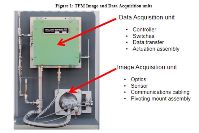
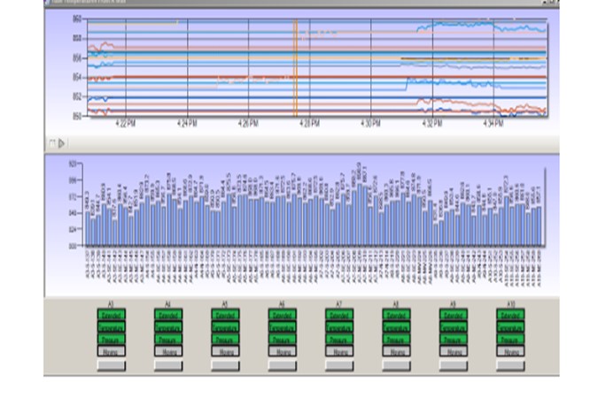
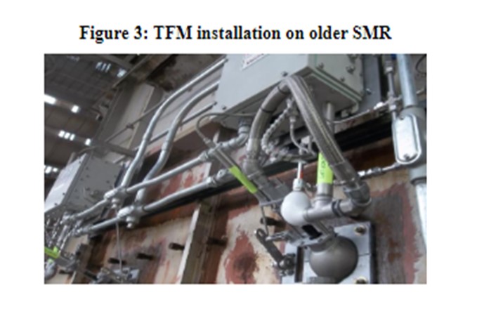
Haldor Topsoe’s technology for monitoring furnaces, including tube temperatures, is Topsoe Furnace Manager (TFM). TFM is a system of multiple image acquisition and data acquisition units installed permanently on a fire box to monitor burner flame intensity, tubeskin temperatures, and firebox component mechanical integrity continuously, 24/7. TFM captures images of the fire box within each unit field of view every second, and stores those images in a historian, for future reference. TFM provides alarms for temperatures outside of the designated operating envelope, with continuous displays in the control room, as well as remotely, with computer networks. Immediate operational issues are known on the control room displays, and longer-term planning is facilitated with images archived in the Historian to enhance overall effectiveness and operational excellence for the entire furnace support organization.
TFM is commercialized on three continents at multiple locations. Reliability of the system overall is equivalent to the plant utilities supply (instrument air and power) and is enhanced by the inherent design encompassing multiple image and data acquisition units on the same fire box. Tube temperatures and burner intensity are graphed and charted similar to process control parameters.
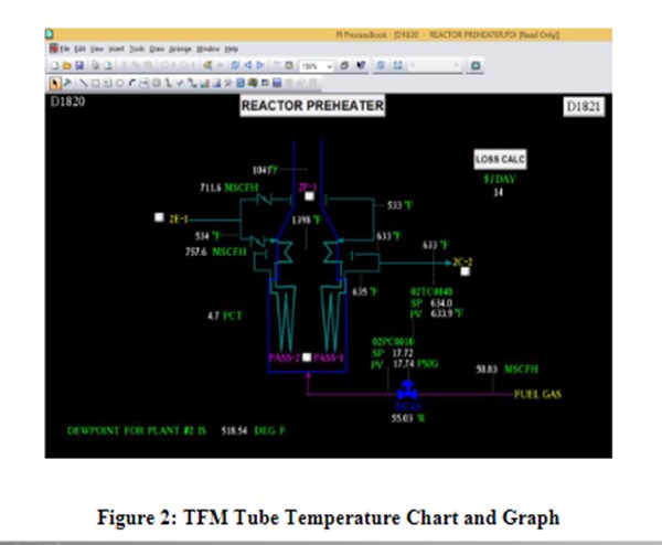
Human interaction with the fire box is greatly reduced due to the remote accessibility of TFM data and the continuous display of images in the control room. TFM data is captured and archived automatically so that data transfer handoffs are minimized. TFM is built for industry with Class1 Division2 components and made for harsh industrial furnace applications. All systems are installed with maintain ability and safety in mind so that furnace operations can be managed with more productive use of personnel time and energy. Data analysis and evaluation is facilitated over current practices involving firebox data acquisition by personnel.
PAT BERNHAGEN (Amec Foster Wheeler)
Tubeskin thermocouples (TSTCs) are a primary way of monitoring the tube metal temperature on a regular basis. Other methods, such an optical pyrometry and thermal imaging, are useful on a periodic basis, although both have limitations. The TSTC can only monitor a specific spot in the heater, and its readings can be impacted by the burner flames if not properly shielded. Pyrometer and thermal imaging readings are impacted by background effects and scale/fouling on the tube OD (outer diameter). A combination of these methods is useful: Use the imaging tool to locate the hot spots in the heater; and later, properly install TSTC at that location. Thermal readings can then be indexed to that spot (assuming the TSTC is more accurate) for full coil monitoring. Proper installation of the TSTC is the most important part of the monitoring process. It is best to follow the manufacture’s guidelines on installation and expansion loops or perhaps have them supplied and installed by the manufacturer.
Year
2016
Process
Question 23: How do you operate mid-distillate selective recycle hydrocracking units to generate more naphtha while minimizing fuel gas/liquefied petroleum gas without catalyst replacement?
JEFFREY MUELLER (Marathon Petroleum Company)
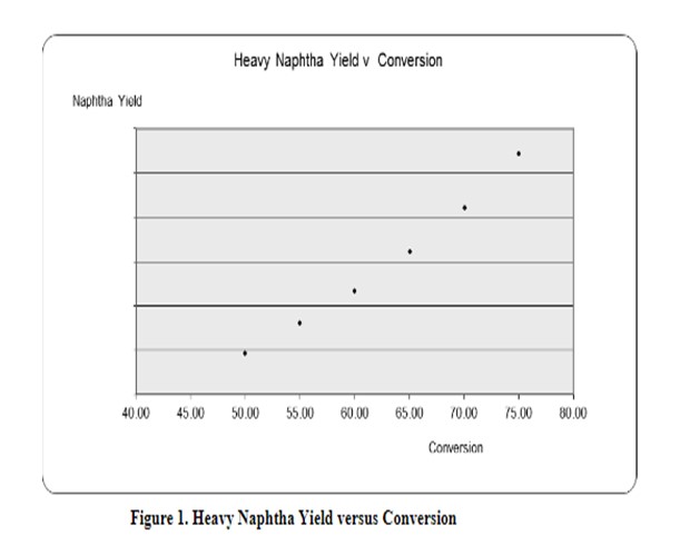
Maintaining flexibility to make gasoline versus ULSD (ultra-low sulfur diesel) is very important to most refiners today due to the volatile nature of the market. Understanding the economic goals of your process unit and building in the flexibility through your catalyst selection process is the best way to set up your process for flexibility in the coming run. This question is very specific in nature but could probably be simplified to: How do I maximize naphtha production in my unit while minimizing light ends production? Simplistically, you need to increase conversion. KBC assisted in development of this answer by running some kinetic models on a recycle hydrocracking unit. Figure 1 shows that increasing conversion will result in a higher naphtha yield.
How to increase conversion is key. From a process variable perspective, there are three actions that will help maximize your naphtha yield and minimize light-end production from over-cracking:
*Maximizing your recycle rate,
*Minimizing your peak reactor temperatures, and
*Reduce your UCO (unconverted oil)/distillate cut point.
Maximizing the recycle rate will decrease your per-pass conversion. You will be able to achieve the same naphtha yield at lower WABT, thereby allowing the process to be more selective to naphtha versus light-end production. A combination of maximizing recycle rate and optimizing WABT will allow you to increase overall conversion without overcracking.
High reactor temperatures directly increase reactor rate. The higher the temperatures, the more “overcracking” of naphtha into gas/LPG that will occur, and the more undesirable light ends which will be produced. Therefore, it is imperative to minimize peak temperatures in your hydrocracking reactors. This goal can be achieved by balancing your reaction across all of your catalyst beds and using quench to control your axial temperatures. In addition, you should ensure radial temperature spread is tight, if possible. Maldistribution across a reactor bed, either from underperforming distribution trays or uneven catalyst loading, can cause high radial peak temperatures and overcracking.
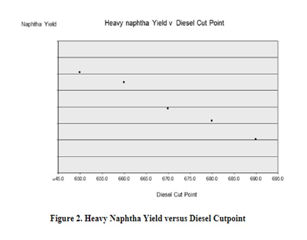
Reducing your UCO cut point results in recycling more distillate material through the hydrocracker reactors which will increase naphtha yield. As you can see from Figure 2, there is a direct relationship between the naphtha yield and the amount of diesel that is dropped into the reactor feed (either by dropping lighter material into the recycle or, if economical, dropping diesel down into your hydrocracker feed at the crude unit).
Finally, do not forget to turn on all fractionation knobs on the back end of the fractionator. Increasing naphtha endpoint by adjusting fractionation is a way to produce more naphtha, assuming that the higher endpoint material can be managed by the reformer or blender.
DAVID VANNAUKER (Haldor Topsoe, Inc.)
In general, mid-distillate (middle distillate) [J+D (jet plus distillate)] selective hydrocracking catalysts contain lower-activity (content and/or acidity) zeolite and/or specialty zeolite as compared to naphtha-selective hydrocracking catalysts. Depending on the specific types and quantity of hydrocracking catalysts, the specific operating changes can vary considerably. Several techniques are recommended to modify these changes.
*Increase pretreat conversion (i.e., aromatic saturation) to produce easier-to-crack molecules.
*Raise HDC WABT (weighted average bed) to increase naphtha make; and/or
*Increase recycles to reduce crack per pass (CPP) to increase selectivity of naphtha over fuel gas/LPG (liquefied petroleum gas) make.
*Adjust the hydrocracking beds to be in a descending temperature profile to minimize secondary and tertiary hydrocracking reactions.
*Lower the endpoint of the distillate product (reduce diesel/UCO cutpoint).
JOE FLORES (Criterion Catalysts & Technologies/Zeolyst)
In a hydrocracker unit with recycle, reducing the recycle product cutpoint IBP (initial boiling point) of bottoms or FBP (final boiling point) of final product before bottoms will increase the conversion per pass (at same overall conversion), which will result in more naphtha.
Higher recycle rates operated with the same conversion level increase middle distillate selectivity. Lowering recycle rates, operated with similar conversion, increase the naphtha production. Up to a certain conversion, the amount of gas make can be controlled based on changes in recycle rates: higher recycle rates reduce WABT and catalyst severity and make fewer light ends and less gas.
In general, when there is an increase in naphtha, there will be an increase in gas make. The volume makes from the fractionator bottoms and middle distillates converting to light ends offset the naphtha volume lost into making additional gas make until a certain optimum conversion is achieved. Hence, additional gas make depends on the targeted conversion, and the conversion distribution between the first stage and the second stage (for two-stage units), as well as the type of catalyst and feeds.
Refiners should also consider recycling/feeding some diesel to make more naphtha as long as they are not above a conversion point where they would make more gas and the net C5+ would decrease.
Year
2016
Process
Question 22: Describe your strategies for optimizing the pretreat and cracking catalyst cycles. How does this strategy vary when operating between maximum naphtha and maximum distillate modes? How does this impact catalyst selection for the next cycle?
JEFFREY MUELLER (Marathon Petroleum Company)
Marathon Petroleum Company has adopted the philosophy of optimizing the hydrotreater and hydrocracking catalyst together as one unit. We do not measure nitrogen slip from the hydrotreater section, but rather allow the hydrocracker apparent conversion dictate adjustments to the pretreat section.
The hydrocracker is operated at temperatures as needed for a specified conversion, with individual bed temperatures varied to establish equal T (equal reaction) in each bed. An overall WABT is calculated and compared to our standard budget curve for the required cycle length. The hydrotreater reactor(s) WABTs are initially set to the budget, and then raised/lowered such that the deviation from budget on the hydrotreater is the same as the hydrocracking reactor.
For example, if the hydrocracker is operating10°F over budget and the hydrotreaters are on budget, the hydrotreater would be increased 5°F with the expectation that a reduction in slip would allow the hydrocracker WABT to be reduced and achieve the same target conversion. Successive moves (slowly, over a period of days) would be performed until the two sections are balanced. The attached graph (a fictitious example) outlines an example of this balancing.
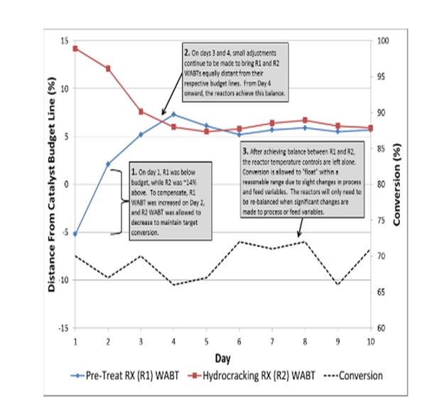
Variations in nitrogen slip due to feed composition changes, etc. will cause conversion to oscillate around an average. However, we will let the oscillations occur and not chase nitrogen slip with hydrotreater temperature. Balancing the reactors in this manner reduces the number of adjustments made throughout the run. MPC has seen those minimizing adjustments and maintaining steady-state operation results in a longer run-length, with more barrels under the curve.
There is no variance in this balanced operating philosophy when operating between max naphtha and max distillate modes. A good understanding of the business objectives of the process unit is needed to optimize the catalyst selection process for the next cycle. Many refiners choose a middle-of-the-road catalyst which will allow the unit to adapt to the volatile market requirements present in today’s business environment (swinging between naphtha/distillate modes).
DAVID VANNAUKER (Haldor Topsoe, Inc.)
Optimization of hydrotreating (HDT)/pretreat (PT) and hydrocracking (HDC) catalyst cycles begins with reactor loading design, which hinges on proposal basis parameters such as unit configuration and operating constraints, desired cycle length, feed (aromatics, distillation, sulfur, and nitrogen), conversion targets, and product selectivity/yield targets. Once the catalysts are loaded and the cycle has begun, both the HDT/PT effluent nitrogen content and the conversion from the HDC reactor are monitored to obtain the respective deactivation rates for the two reactors. Traditionally, the HDT/PT catalysts deactivates faster than HDC catalysts due toa higher coking tendency and contaminants in the feed, which must be considered. In some units, the HDC catalyst activity is sufficient to run twice as long as the HDT catalyst (i.e., changeout the HDT/PT catalyst once mid-cycle through the HDC catalyst cycle). Therefore, the optimum loading is one where both the HDT/PT catalysts and the HDC catalysts reach their end-of-run (EOR) limitations in unison (or, if possible, some multiple of HDT-to-HDC cycle lengths).
For maximum naphtha operating mode, the HDT/PT should be operated as needed to control nitrogen slip (N-slip) and the HDC temperatures should be raised to high conversion. For maximum distillate operating mode, HDT/PT should be run hard for maximum aromatic saturation (ASAT) while HDC temperatures should be run low for minimum saturation to reduce over cracking (secondary/tertiary cracking reactions) and minimize conversion.
There are three primary options for catalyst selection and the resulting operating window:
1) Select a flexible, medium-zeolite cracking catalyst and achieve the change of product slate through the change of cut point and/or conversion per pass as mentioned.
2) Install multiple cracking catalysts with varying activities/selectivity's such that the product structure can be optimized with bed temps between naphtha and diesel operating modes (Note: Recycle compressor capacity should be evaluated to ensure sufficient reserve quench); or,
3) Utilize HDT catalysts in the HDC reactor up to the limit of naphtha make and minimum naphtha octane. The conversion can swing by as much as 25% between maximum naphtha and maximum diesel, which is a function of catalyst volume [LHSV (liquid hourly space velocity)] in the hydrocracking reactor(s), so smaller units (i.e., smaller catalyst volumes/LHSV) will have a smaller potential conversion range. The key for catalyst selection is determining the optimal midpoint. Once this is defined, the new catalyst selection can be made.
JOE FLORES (Criterion Catalyst & Technologies/Zeolyst)
The main strategy for HCPT (hydrocracking pretreat) catalyst is to adjust average temperatures (WABT) throughout the cycle to achieve the designed nitrogen (N) slip (or its indications) to the cracking catalyst. Note that the N slip can be allowed to increase, which will affect the selectivity of the HC catalyst to be more diesel selective. The WABT is held at this temperature until excessive N slip is measured, or symptoms of N slip are observed, in the cases were Nslip cannot be measured. Desired delta T in first bed of cracking (at a target bed average temperature) provides an indirect measure of the N slip from pretreat. Based on pretreat catalyst deactivation, pretreat WABT will need to be increased to meet minimum N slip requirement for the cracking catalyst throughout the cycle. Therefore, choosing a catalyst which provides both high activity and strong stability will allow pretreat temperatures to be lower over the cycle.
An alternative pretreat strategy is to operate HCPT at the optimum temperature for maximum aromatics saturations initially [during SOR (start-of-run)] and then to hold that temperature through the cycle. This technique is often used with LCO or high aromatic feeds to maximize volume gain and is shown in the graph below.
Note that every unit has a defined operating window in each of the HCPT and HC catalyst systems, as set by the delta between SOR and EOR temperatures. This delta, along with an estimated catalyst deactivation rate, will identify how much flexibility –or lack of flexibility –is available throughout the cycle for other parameters such as metals poisoning, processing heavier feeds (in the HCPT) or increasing N slip, or increasing conversion beyond the cycle operating goal (in the HC). Due to optimization efforts, units tend to have limited flexibility in their operating windows. And as an example, operating to a constant N slip and/or constant conversion is important in order to make a defined cycle as per the cycle operating goal, as shown in the next graph.
For HCPT, optimum catalyst utilization and maximum HCPT cycle life is achieved by operating to equal outlet bed temperatures as this results in each bed deactivating at similar rates. Some units have to operate pretreat in ascending profile due to heat integration limits in the units or to optimize metals uptake.
The main strategy of the HC catalyst is to operate to the design conversion. Optimum catalyst utilization is achieved by operating to equal bed dTs, which results in each cracking bed deactivating at similar rates. Equal dT operation in cracking beds often ends up with descending temperature profiles (since HC Bed 1 sees the highest nitrogen slip and aromatics slip from the pretreat beds). This bed is required to operate at the highest temperature to provide the same dTs as the beds below. In addition, a descending profile is usually not a safe way to operate; when recycle gas is lost during an upset, it could lead to an exotherm in all subsequent beds. Hence, we usually recommend a lower axial dT target for Bed 1 in hydrocracking, and equal dTs for other beds, to be able to target similar outlet temperatures at each cracking beds.
For cracking beds with very different volumes, the equal delta T strategy may need to be modified to suit the deactivation rates and peak temperatures profile. When operating between max (maximum) naphtha and max distillate modes, the equal dT strategy may need to be modified as EOR is reached, and the cracking bed temperatures start to approach mechanical limitations. Under these conditions, temperatures may need to be shifted to extend the catalyst cycle. Overall, the strategy is to utilize all catalyst beds during the cycle.
Typically, increasing conversion beyond the design will result in additional naphtha production (decrease in diesel), and a decrease in conversion will result in less naphtha production (and marginally more distillate material). Therefore, operating in a max naphtha mode normally would require the HC catalyst to operate at or above design conversion (and above estimated WABT) and up to the downstream gas plant limit. In max diesel mode, the HC catalyst would operate at or below design to maximize the distillate yield.
One must decide early which mode of operation (naphtha or distillate) will be desired for the next cycle so that the best catalyst solution for HCPT and HC combined is chosen. Operating a distillate selective catalyst in naphtha mode will not yield the optimum naphtha yield or cycle life, and operating a naphtha selective catalyst in distillate mode will not yield the optimum distillate yield. The correct mode of operation should be decided by involving the economics and planning department during the selection process in order to maximize profitability. In addition, RFQs need to be based on the most realistic case, and not the worst case, in order to make the best possible catalyst decisions.
Max naphtha catalysts offer longer cycle length when compared to max distillate catalysts. They often provide the highest volume yield due to their ability to operate at higher conversion, unless the feed is very easy; then, the conversion can be too high, because more naphtha will be converted to gas than distillate to naphtha.
Max distillate catalysts typically have lower activities, will operate at higher temperatures at equal conversion when compared to max naphtha catalysts, have lower selectivity towards naphtha, and higher selectivity towards distillates, and have lower gas make. Due to their lower activity, these catalysts will typically offer shorter cycle length when they are operated in max naphtha mode. At equal conversion, they often offer higher volume yields when compared to max naphtha catalysts due to higher aromatics saturation and lower gas make.
The optimum catalyst solution is determined by working closely with a catalyst supplier and considering individual refinery economics (including volume gain), cycle length requirements, and unit hardware constraints.
Year
2016
Process
Question 20: When is it appropriate to neutralize austenitic stainless-steel equipment to protect against stress corrosion cracking (SCC)? What neutralization procedures and methodologies do you recommend?
JEFFREY MUELLER (Marathon Petroleum Company)
Background
Austenitic stainless steels (200-and 300-series steel) are the most common type of stainless steels. Austenite refers specifically to the geometry of the steel (face-centered cubic crystal). These types of steel are most typically recognized as non-magnetic. Austenitic steels are widely used in the industry because they have very desirable mechanical properties. Their austenitic structure is very tough and ductile down to absolute zero. They also do not lose their strength at elevated temperatures as rapidly as ferritic iron base alloys.
One negative aspect of austenitic steels is that they are susceptible to polythionic acid stress corrosion cracking (PTA SCC). PTA SCC refers to an intergranular form of cracking that can occur in sensitized austenitic stainless steels and other sensitized austenitic alloys. The following photo1shows intergranular stress cracking of a heat exchanger.

Polythionic acid refers to the family of acids that have the form H2SxOy, where x is generally considered in the range from 1 to 5, and y may range from less than 1 to 6. Polythionic acids are formed when sulfide corrosion products on the internal surface of equipment (e.g., iron sulfide) reacts with oxygen and water.
Sensitization is a metallurgical condition caused by specific heating, cooling, and/or deformation processes that result in precipitation of constituents (for example, chromium carbides in stainless steel) at grain boundaries, which results in the grain boundary being more susceptible to intergranular corrosion. Sensitization can occur in hydroprocessing units that run at higher operating temperatures.
1https://www.nace.org/uploadedImages/Corrosion_Central/Corrosion_101/intergrainscc.jpg.
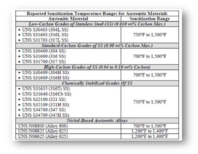
The critical level of sensitization and stress required to initiate PTA SCC are not well understood. The rate of sensitization can be directly correlated to an increase in temperature within the sensitization temperature range. In addition, the rate of sensitization varies based on the composition of the steel. Certain grades of austenitic steel are “chemically stabilized” with titanium or niobium to alter the sensitization temperature range and thus can be resistant to PTA SCC.
The following table shows the reported sensitization temperature ranges for some austenitic materials.
Protecting Against PTA SCC
The first step in preventing PTA SCC is understanding the location(s) in the process where it can occur. In hydroprocessing units, the risk is higher due to the fact that the process operates in a reduced atmosphere (no oxygen or CO2), making it conducive to the formation of high-temperature iron or other metal sulfide scale. Most typically, sections of the reactor circuit operate in the appropriate temperature range andcorrect metallurgy to be at risk of PTA SCC. Within the circuit, stainless heater tubes are another common place for this attack [both ID (inner diameter) and OD (outer diameter)].
Neutralization, or alkaline washing of the equipment surface, is one method used to prevent PTA SCC. In this process, the equipment is rinsed with a soda-ash solution [approximately 2 wt% (weight percent) to neutralize any acids formed at the metal surface and, after draining, leave a thin alkaline film on the surface that can neutralize any additional acid formation. This wash must occur prior to exposure to air (and prior to opening any equipment), and all of the equipment’s internal surfaces must be contacted for the washing to be effective.
Some important notes about the procedure are as follows:
*The system should be filled with alkaline solution under an inert atmosphere to minimize oxygen contamination.
*The equipment should be soaked, or the wash solution circulated for a minimum of two hours.
*At all times, the solution should maintain a minimum pH of 9 and a chloride limit of 1000 ppm.
*Reactor inlet and outlet spools should be sprayed with solution under inert atmosphere, immediately wrapped with plastic, and stored out of weather until reinstalled.
There are potential downsides with an alkaline wash procedure. Chlorides in the wash water and the process unit (ammonium-chloride salts) can lead to chloride SCC of the steel. A sodium nitrate (NaNO3) corrosion inhibitor may be added to the wash solution to reduce the likelihood of chloride SCC. In addition, a maximum chloride concentration of 1000 ppm should be honored during the wash. It is important to have a good rinse step after the wash procedure, as any residual wash water can concentrate during the heat-up process and result in chloride or alkaline stress cracking.
There are other means available to protect against PTA SCC. They include:
*Appropriate Material Selection: Selecting a stabilized grade of austenitic steel where PTA SCC is less of a concern.
*Appropriate Fabrication Methods: Heat treatments to maximize resistance to sensitization should be conducted after all hot and cold forming operations.
*Avoidance of Oxygen Entry: Using nitrogen to keep air out of a process if the shutdown does not involve invasive work of a piece of equipment. (Important: Make sure the oxygen level is less than 50 ppm in nitrogen. Users have found oxygen levels as high as 1000 ppm in commercial nitrogen.)
*Avoidance of Water Entry: Using a dehumidified air purge for protection against PTA SCC is acceptable if the dew point temperature of the air entering the vessel is maintained a minimum of 40°F lower than the internal surface metal temperature. It is important to remember that in process heaters with stainless steel tubes, it is critical to protect the OD of the tubes from PTA SCC. This is most commonly applied at Marathon Petroleum Company (MPC) by maintaining temperature inside process heaters (firebox) with austenitic stainless-steel tubes well above dew point. This is typically accomplished by maintaining some pilots or inserting a portable heater into the firebox during the outage. Sample Procedure The following are key excerpts from a successful neutralization procedure from a distillate hydrocracker at an MPC refinery.
*All austenitic stainless (300 series) steel equipment that has been exposed to temperatures greater than 700°F (can be higher/lower based on MPC guidance) must be neutralized prior to exposure to any source of air (oxygen) and water. Stainless steel equipment that is in contact with sulfide corrosion products may be susceptible to polythionic acid stress cracking (PASCC) if the corrosion products are exposed to contributing factors such as oxygen and water, and if the austenitic material is in a high degree of sensitization.
*For this shutdown, the “hydrogen reactor heater” will remain under an inert atmosphere and will not require neutralization. The convection section of “debutanizer tower reboilers A” is being replaced, so neutralization of this heater will need to occur during this shutdown.
The components identified to need neutralization must be:
*Neutralized with a soda ash solution before exposure to oxygen or water, A chemical handler, such as PSC, should assist in the process. An N2(nitrogen gas) blanket/purge should be completed before blinding.
*Hydro blasted with soda-treated water,
*Hydrotested with hydrocarbon,
*Protected by the soda ash film for the duration of the turnaround, or if the protective film is removed by any subsequent water wash, rain, or mechanical work, it must be reapplied with hand-held sprayers.
*Kept under an inert atmosphere. Three neutralizing circuits will be set up in order to accomplish the process. The circulating solution should consist of the following:
*Condensate is preferred for making the solution, but other water sources may be considered if the chlorides meet the specifications.
*The desired solution is 2 to 2.5 wt% soda ash.
*Addition of 0.4 wt% sodium nitrate as corrosion inhibitor is recommended.
*Addition of 0.2 wt% alkaline surfactant to increase the penetration of oily films and residues is suggested.
*The solution should have a maximum of 50 ppmw (part per million by weight) chlorides, which must be tested prior to use with the chloride test strips that can be obtained from the lab.
*After the catalyst is unloaded and the atmosphere is still inert, the reactor walls/internals should be neutralized. Sprayers with soda ash solution should be used to coat the wall and internals. Throughout the duration of the reactor work, the soda ash solution should be reapplied if the protective coating is removed by water or mechanical work. Any internals (ells, flanges, quench nozzles, thermowells, quench check valves, etc.) removed from the system must also be sprayed as soon as possible. The following needs to happen during neutralization:
*Fill each circuit with neutralization solution. Vent at high points until solution spills to ensure that each circuit is liquid full. Circulate at a target of 200 gpm (gallons per minute) for a minimum of two hours.
*Maintain circulating temperature above 120°F, which may require vendor steam heat (200°F upper limit).
*Monitor the pH and chlorides every 30 minutes; do not go below 9 pH and do not exceed 250 ppm chlorides. The following needs to happen after neutralization:
*Each circuit will be drained into a frac tank before the solution is sent to the WWTP (wastewater treatment plant). If acceptable, spent solution from spraying the reactor internals and ID will be drained directly to sewer.
*A sample from the frac tank should be taken to the lab to test for pH, COD (chemical oxygen demand, TDS (total dissolved solids), Cls (chlorides), and ammonia. Based on these tests, the WWTP will advise on how quickly it can be drained to sewer.
*Drain all low points in the circuit. If water is left in any low points, the bleeders are subject to potential alkaline stress corrosion.
*Use fresh soda ash solution for hydro blasting and hydrotesting.
*Protect bundles and equipment from rain to avoid removing protective coating.
*Prior to equipment start-up and heating of equipment, a hydrocarbon flush should be conducted to flush residual solution out of the system (not practical on the recycle gas and RX (reactor)inlet circuits). Drain all low points in the circuit again.
Year
2016
Process
Question 24: How do you manage reactor maldistribution once identified?
PATRICK GRIPKA (Criterion Catalysts & Technologies)
Once maldistribution is identified, safely managing it depends on the unit, feedstock, and unit objectives. If the extent of maldistribution is not impacting safety, then it is an economic decision whether to:
*Manage to the end of the cycle,
*Manage to a convenient turnaround point, o.
*Shut down and correct immediately. The decision and the mitigation actions will also depend on how the maldistribution is observed.
*Differential pressure (dP; ∆P; delta P) issues can be handled by adjusting feed rate and gas rate to keep dP below the maximum until a unit skim or changeout can be taken. Use of chemicals to reduce dP can work for short times if the dP is due to FeS (iron sulfide) particulate agglomeration.
*Radial thermocouple spreads can be an issue if the radial exceeds the accepted Best Practice or if it leads to a peak thermocouple being reached at a much lower overall bed temperature than expected. In both cases, feed management (i.e., removal of most reactive feeds) and/or adjustment of feed and gas rates are items which can be adjusted. If product quality is impacted, then feed management may get the unit back on-spec (on specification). If feed management does not resolve the issue and the product spec cannot be relaxed, then the unit will have to be shut down.
In any of these circumstances, understanding the cause of the maldistribution is critical; and if the cause is undetermined or uncertain, a careful observation and review should be completed during unloading.
JEFFREY MUELLER (Marathon Petroleum Company)
Reactor maldistribution is a phenomenon that is typically caused by inadequately designed or installed reactor internals, improperly/unevenly loaded catalyst bed, catalyst migration from an upstream bed, or process fouling. The main problems generated by flow maldistribution are the overuse of part of a catalyst inventory and the formation of hot spots, which can create a process safety risk, as well as limit the performance of the cycle. In a hydrocracker, hot spots present a serious process safety concern, as well as contributing to over cracking which can lead to reduced liquid product selectivity.
Reactor maldistribution can be recognized by an increase in the radial temperature spread, an increase in the measured bed dP, or both. Once maldistribution is identified, the most important items to understand are the safety implications and set limits accordingly. A refiner should be monitoring all radial bed temperatures and honor any peak temperature limitations. It is also important to consider that your temperature indicators (TIs) are only a snapshot of the bed. As your spread increases, you should consider being more conservative on your peak temperature limit, considering the logic that you may have hot spots that are non-detected due to the spacing of the TIs. Additional monitoring of the reactor walls, either by IR scan or installing temporary TIs should be considered in the bed where maldistribution is occurring. In addition, monitoring individual reactor bed dP versus loading limits is important, as maldistribution can be tied to pressure drop if catalyst migration is a causal factor or if the maldistribution has caused coke balls to form within the reactor bed.
There is little or nothing that can be done, on the run, to manage maldistribution issues caused by distribution tray issues. This type of maldistribution is typically recognizable because it is near the top of the bed. The obvious answer here is to replace or repair the damaged tray at the next catalyst change.
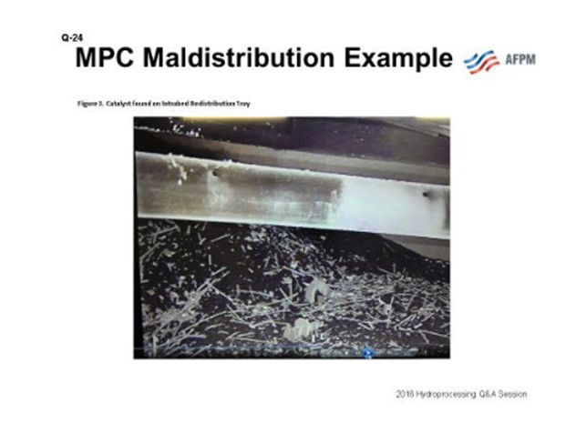
Depending on the source of the maldistribution, an immediate outage may be required to remedy a process safety risk. Recently, on an MPC hydrocracker, an impromptu mid-cycle outage was taken to screen and reload the top few beds of the hydrocracker reactor after maldistribution was detected due to a loss in catalyst containment from one bed into the redistribution tray. This catalyst migration issue was diagnosed from an increase in bed radial distribution spread corresponding to an increase in reactor pressure drop (see Figures 1 and 2).
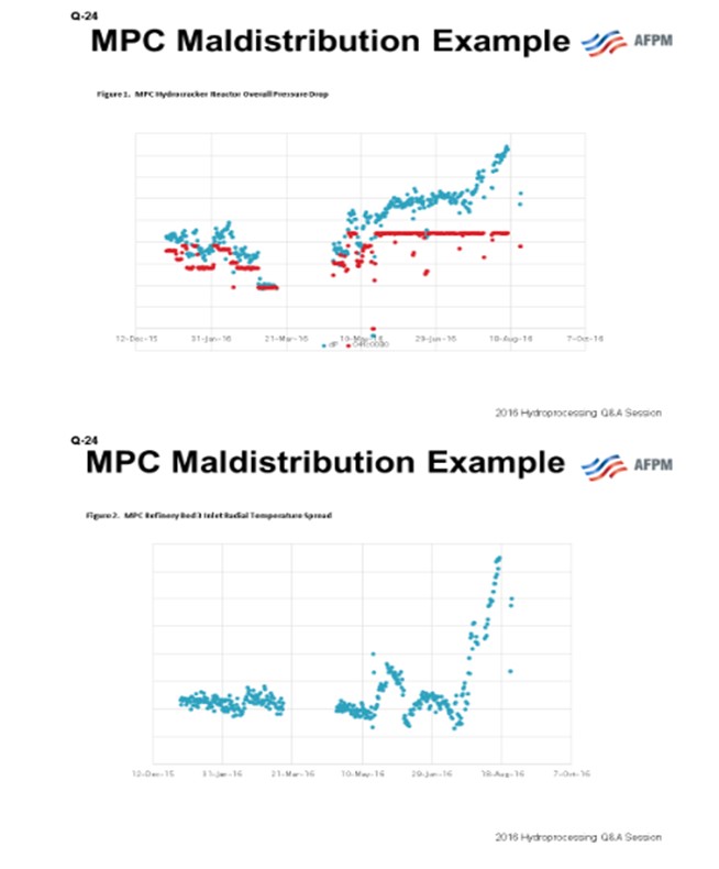
The data pinpointed the issue to an initiating event: an unplanned unit shutdown due to a refinery hydrogen upset. Figure 3 is a photo taken from inside the reactor during the catalyst removal showing the migrated catalyst on the redistribution tray.
JACOB BRIX (Haldor Topsoe A/S)
When reactor underperformance has been confirmed to be caused by maldistribution, two separate tracks are normally started in parallel. The first is to limit the impact on the current cycle length by following the pressure drop, deactivation, and product specifications. Depending on the observations, small modifications –such as a calculated change in gas/quench rate or a small change in feedstock properties –can help to extend the cycle.
The second track is to investigate the cause. Maldistribution can either be caused by internals malperformance or by channeling initiated in the bed. If there is evidence of internals malperformance, the refiner should ask Haldor Topsoe to evaluate the benefit of installing new Topsoe distribution VLTs (vapor lift trays) and a Torus™ mixer which can, in most cases, be paid back in a matter of months due to better performance and reduced downtime. Maldistribution in the bed can both be initiated after an upset, which caused coking, or at the start-of-run if the loading was not ideal.
Year
2016
Process
Question 27: What methods do you use to reduce particulate loading on or debottleneck of existing filtration equipment in a HPU unit without reducing catalyst cycle life?
DAN MORTON (Haldor Topsoe, Inc.)
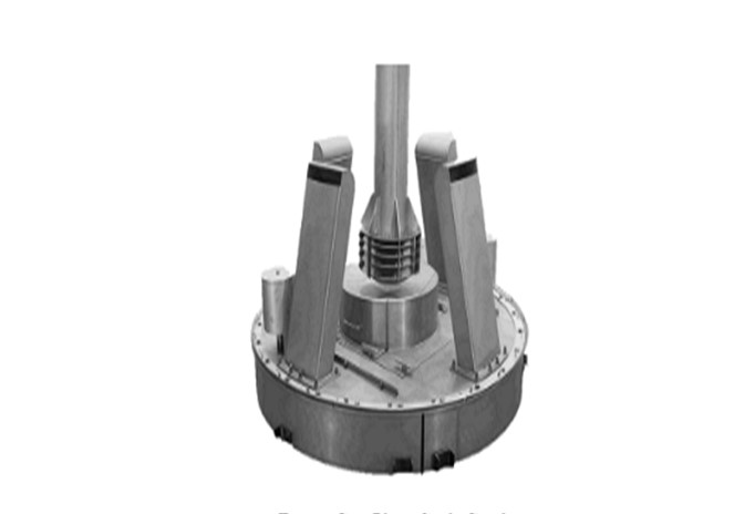
The use of feed filters is highly recommended, but it is important to choose a filter size that will be manageable; meaning that if a 5-micron filter is used, it will most likely have to be replaced or backflushed several times per day, which is not practical. However, if a too-large filter size is used, it will not be effective. The only way to reduce the particulate loading on a feed filter is to increase the filter size, thus allowing more material to slip through. In order to notimpact the catalyst life cycle, it will be necessary to install a scale catcher in the reactor to catch the extra material that is now going to the reactor. The scale catcher is located on top of the inlet distribution tray (i.e., above the tangent line) and will not reduce the catalyst volume in the reactor.
The scale catching tray will collect the fines, scales, etc. in order to avoid plugging of the distributor tray and the catalyst bed below. Haldor Topsoe has developed very effective scale catchers for both gas-phase and liquid-phase hydroprocessing units.
Single-Phase (Gas) Flow
The gas-phase scale catcher removes particles from the gas. The equipment is designed specifically for the type of particles typically seen in a naphtha feedstock.
Two-Phase (Liquid and Gas) Flow
There are two primary designs by Topsoe for scale catching in two-phase flow: a single-stage filtration tray for larger particles and a dual stage filtration tray, called the HELPsc™ (High Efficiency Low Pressure) scale catcher.
The single-stage scale catcher is made to simply allow the larger particles (greater than 100 microns) time to slow down and settle out of the liquid flow and then precipitate out onto bottom of the scale catcher. They canthen accumulate and be easily cleaned/vacuumed out at the next turnaround. These heavy particles never reach the bed below and plug the catalyst.
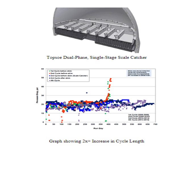
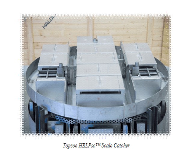
Haldor Topsoe HELPsc™ Technology
Haldor Topsoe’s second generation High Efficiency Liquid Phase scale catcher (HELPsc™) is a two-phase, dual-stage catalyst basket scale catcher which provides improved retention of both the large and much smaller particles in the range of 10 to 20 microns, resulting in further improvements in cycle length. The technology provides a dual-stage system for improved scale-catching efficiency, providing combined sedimentation and filtration stages.
Dual Filter Principle for Liquid Flow:
1.Liquid accumulates on the tray.
2.As soon as it reaches the right height, it flows into the filter catalyst cassettes.
3.The liquid is pushed through the first (and the second) filtering unit until the pressure drop across the filter causes the liquid height to grow over the filter.
4.When the liquid height exceeds the height of the first filtering chamber, the liquid bypasses the first filter, collects in the space between the two filters, and is pushed through the second filter.
5.Eventual bypass of the dual filter system occurs when it reaches capacity.
6.No pressure drop is accumulated over the entire life cycle of scale catcher tray. The two-filter chambers are filled with a specialty catalyst in two different sizes to further improve the filtration efficiency. For additional information, please contact your Haldor Topsoe representative.
SANDER VAN SCHALKWIJK (Shell Global Solutions)
We can distinguish two scenarios. First, fouling material is coming from the upstream unit or from storage tanks. In this case, a feed filter (cartridge type or backwash type) installed on the feed line can solve the fouling issues by capturing the fouling material coming from the upstream unit. Another option is also to install a “deep bed” filter on the feed line, which is basically a small guard bed reactor full of grading material. Feed filters have a higher capex (capital expense) than the deep bed filter, but no opex (operating expense). The grading in the deep bed filters must be changed once it is plugged leading to higher operative expenses and requiring more maintenance.
Second, fouling material is produced within the unit. In this case, in order to capture the fouling material produced within the unit and upstream the reactor, grading can be loaded on top of the catalyst bed and/or a scale catching tray/filter tray can be installed above at the top of the reactor. Cycle length can be significantly increased by optimizing/loading grading layers on top of the catalyst bed and by also by installing a scale catching tray or filter tray. Filter trays are the best filtration technology we can install in the reactor itself as they capture both big and small sized particles (unlike the scale catching tray which captures big particles only). Of course, a combination of all these solutions can be considered.
Year
2016
Process
Question 25: For refinery complexes considering grassroots or brownfield expansion of gas oil conversion capacity, what are your typical capital expenditure (capex) costs and relative refinery margin improvement between FCC (fluid catalytic cracking) and hydrocracking? What are the key technology features that impact your economic decision? What are the crucial considerations that, if they include both technologies, to allow for future integration, especially around the changing gasoline/diese
JEFFREY MUELLER (Marathon Petroleum Company)
Capex (capital expenditure) costs are very unique to each specific refinery. Offsite investments (tankage, utilities, etc.) and downstream unit configurations are very significant and must be considered when determining an investment strategy around an FCCU versus an HCU (hydrocracker unit).
One of Marathon’s engineering contractors provided the following ISBL (inside battery limits) costs per barrel for a grassroots FCCU versus an HCU:
FCC: $6,200/bbl(barrel) to $7,000/bbl
HCU: $7,200/bbl(Partial Conversion) to $9,000/bbl(Full Conversion)
A couple important points:
*FCCU products may need to undergo further processing to remove sulfur to meet specs. This is not included in the costs.
*The above-quoted values are for units in the 50 to 70 mbpd range.
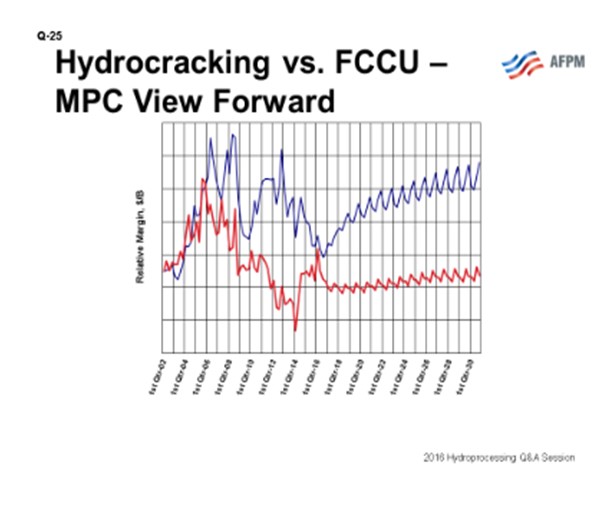
In general, Marathon’s economic viewpoint is that hydrocrackers have better projected margins going forward than FCCUs, as they maximize higher valued ULSD over gasoline and have higher volume expansion (see Figure 1). This is driven by many factors mentioned in the primary response and is particularly attractive when ULSD is strong relative to gasoline and when natural gas or hydrogen) is inexpensive. Each company has a different viewpoint on this topic, so the opinion will vary somewhat across the industry.
HOWARD WU (Haldor Topsoe, Inc.)
Selection between FCC and hydrocracker as the conversion process for gas oil requires detailed analysis of feed qualities, desired product slate and properties, and local economics.
An FCC unit can, in general, process a wide range of materials including gas oil, deasphalted oil, and residual oil. On the other hand, the hydrocracker, while it can also process a wide range of materials, operates better with a cleaner feed.
FCC is a thermal, catalytic carbon-rejection process, and it naturally produces lower C5+liquid yields with lower product qualities than hydrocracking, which is a high-pressure, hydrogen-addition process. Typically, an FCC unit, for a maximum gasoline mode, would make 4 to 7wt% dry gas, 25 to 30 vol% (volume percent) LPG, 55 to 65 vol% gasoline, 15 to 20 vol% LCO, and 4 to 10 vol% decant oil. All of these FCC product streams require further cleanup and processing to become usable materials. The flue gas needs to be scrubbed to meet the SOx (sulfur oxide) and particulate emission requirements. The gasoline product needs to be hydro treated for sulfur removal. The cycle oil, because of its high density and low cetane index (typically low 20s), needs to be severely upgraded in a hydro treater to be a usable diesel blending stock. The decant oil, because of its high density and low hydrogen content, often can only be used as fuel oil. However, a specific advantage for FCC unit is that it could produce a large number of light olefins for alkylation or Petro chemical applications.
Hydrocracking is a versatile process; and with a proper design, the unit can achieve almost 100% conversion with flexibility to swing between naphtha-focused or diesel-focused operation, depending on the need. Typical yields for a full conversion hydrocracker using a flexible catalyst to swing between naphtha and diesel modes are: 0.2 to 0.4 wt% dry gas, 6 to 13 vol% LPG, 28 to 48 vol% naphtha, and 54 to 85 vol % jet and diesel combined. If the unit is designed to make maximum naphtha, the total naphtha yield could be as high as 115 vol%. Light naphtha from a hydrocracker often can be blended directly into gasoline pool. The heavy naphtha is typically sent to the reforming unit for an octane boost. The reformer generates hydrogen, but a hydrogen plant is likely required to supplement the hydrogen need of the hydrocracker. The jet and diesel products require no further processing; they often exceed the smoke point and cetane requirements, respectively.
Once the product slates for the FCC and hydrocracking processes are known, the economic advantage for one process versus the other can be calculated. The following chart (data from the United States Energy Information Administration) can be used as a reference with regard to the cost and prices of the transportation fuels:
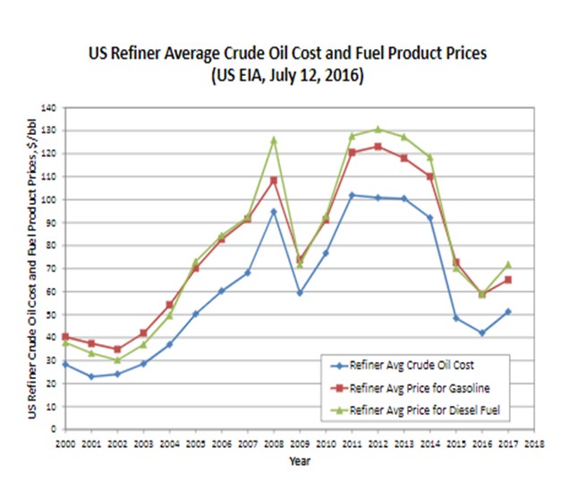
It can be seen that from years 2005 to 2014 diesel to crude oil has a larger spread than gasoline to crude oil; for year 2015 the trend had reversed; and for the current year 2016, the two seem to be equal. The EIA (Energy Information Administration) is currently predicting price advantage for diesel for 2017. Several refineries have recently reported that between summer and winter, there is a significant difference in profit between making gasoline and making diesel fuel. Therefore, without knowing what the future would hold, it seems that having flexibility to make more naphtha or diesel would be important to a refiner. The importance of operating flexibility gives an advantage for the hydrocracker over the FCC because of its greater ability to swing between these two operating modes.
Estimating required expenditure for erecting an FCC unit or a hydrocracker would require detailed analysis. In general, a hydrocracker would cost approximately 30% more than an FCC unit. However, for an FCC complex, having a pre treater or a post-treater (or both, in some cases) most likely would be required given the upcoming gasoline tier 3 ultra-low sulfur specification (10 ppmw). In addition, as mentioned above, the cycle from the FCC unit will need to be processed before it can become a usable product. Considering these pretreat and/ or post-treat requirements, an FCC complex may cost the same or more than a hydrocracker complex with hydrogen plant and naphtha reforming capacity.
If a refinery has both an FCC unit and a hydrocracker, it will obviously have great flexibility to shift between diesel and naphtha productions. Shifting feedstock between these two units automatically changes the naphtha-to-diesel yield ratio. Each unit can be adjusted to maximize production of the desired product. This adjustment is done through changes in cutpoints, catalyst types, and operating conditions. In addition, the cycle oil from the FCC unit can be processed in the hydrocracker and the unconverted oil from the hydrocracker can be sent to the FCC unit. For design, all these aspects need to be considered.
Year
2016
Process