Question 1: How do you manage organic fluoride compounds in effluent and recycle streams in an HF alkylation unit? How do you detect upsets, and how are the impacts on downstream units mitigated?
SHARON (Valero)
Combined fluorides are formed by the addition of HF (hydrogen fluoride) to an olefin. Generally, when you see high organic fluorides in your C3 and C4 streams, it is generally caused by one of the following: low operating reactor temperatures, low acid strengths, low I/O (isobutane/olefin) ratios, or low acid-to-hydrocarbon ratios. C3 and C4 organic fluorides are typically removed via alumina beds. The feed to the defluorinators – that is, the alumina bed – is heated to about 400 to 450°F. Typically, you target about 450°F. The reaction is shown in the following equation:
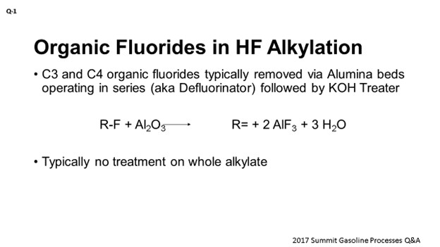
Usually, the alumina will pick about 20 to 25% by weight. The stream is cooled and then treated in KOH (potassium hydroxide) to remove any existing free HF or post-treat. Safety-wise, upsets in the defluorinators are generally caused by free HF. Therefore, you should have midpoint and outlet TIs (temperature indicators) to help detect any large exotherms.
SUGG (Honeywell UOP)
Kyle, good response. From our perspective, very little has changed on this subject since this question was originally posed in 1979. Internal recycle streams were typically not monitored for organic fluoride compounds because they are converted back to HF as they go through the reactor section. We do know one refiner who monitors fluoride compounds in every cycle, but it is not clear to us how the information is used. It is very atypical to monitor.
The alkylate product is typically not defluorinated. Upsets are generally detected by changes in other process variables such as acid purity. However, upsets do go undetected in some units. Reliable online analyzers for organic fluorides are not available. Best Practice is to minimize these undesirable fluoride compounds in the products to maintain a reactor temperature above 80°F, maintain HF purity above 87%, and maintain proper mixing of the feed into the reactors.
ROBERTSON (AFPM)
Those are the responses from the panel. Any questions or comments from the audience? You can also see the results of the poll for this Question on the app. It looks like 92% said no; 8% said yes. Does anyone want to see that on the boards? This is a simple one. It just now changed to 93% to 7%, so 13 out of 14 respondents said no. Maybe somebody hit yes by accident? [Laughter] The result is 93% to 7%.
Results to Poll for Question 1: No = 93%; Yes = 7%
RICHARD TODD (Norton Engineering Consultants, Inc.)
Typically, organic fluorides are managed in the butane and propane effluent streams from an HF alkylation unit. Treatment of the isobutane recycle stream is not needed. The propane and butane products are typically treated in alumina treaters to remove the organic fluorides and then in KOH treaters to remove moisture (which is created in the alumina treaters) and any HF “slip”. The alumina and KOH treaters are each equipped with multiple vessels and arranged in a lead/lag type of system so that the treaters can have the alumina or KOH (potassium hydroxide) replaced with the alkylation unit in service.
Proper monitoring of the organic fluoride content in between the two alumina treaters, as well as the moisture and HF in between the two KOH treaters, is essential to ensuring that the propane and butane products remain free of contaminants that may impact downstream process units. The feed organic fluoride content can also be monitored and tracked, and the “remaining life” in the alumina and KOH treaters predicted, to better schedule changeouts of the alumina and KOH.
Butane alumina and KOH treaters may pose some unique challenges with corrosion as the high organic fluorides in the untreated butane results in high moisture that may become extremely corrosive with any HF slip. Piping and equipment between the alumina and KOH treaters may need to have upgraded metallurgy to manage this corrosion risk.
Year
2017
Process
Question 2: Iron is one of the most common contaminant metals seen on naphtha reforming catalyst. What is the source, what is the impact to yields and operation, and what can be done to mitigate these effects?
DUBIN (Axens North America)
This is a three-part question, so we will try and take it step-by-step. The three main sources we see for iron poisoning of catalyst are from the naphtha feed the hydrocarbon itself metal dusting, and corrosion byproducts. With the naphtha feed, this poisoning is often due to inadequate hydrotreating conditions in the upstream hydrotreater. Or if your hydrotreating catalyst is saturated with metals, you can see some metal slip that will make it into the downstream reformer. Metal dusting is related to removal of the sulfur passivation layer in your heater tubes. This contamination is a problem for moving bed-type reformers, but high temperatures with very low sulfur feeds can elute the iron sulfide off the tube and downstream. And then, the last source is corrosion byproduct, which is very much like it says: corrosion issues from upstream, or wherever else in the plant, that find their way to the reformer.
The impacts these poisoning events lead to are dependent on the type of iron that makes it into the reformer catalyst. The main impacts are generally selectivity and activity, and they are due to a limitation in the redispersion of platinum during the regeneration steps. During oxychlorination, there is an interaction of iron and chlorides that can limit the redistribution. Also, during reduction, hydrogen is blocked from accessing the catalyst pores preventing the system from properly reducing the catalyst. Or during normal operation, hydrocarbon feed is blocked out from accessing the full catalyst performance.
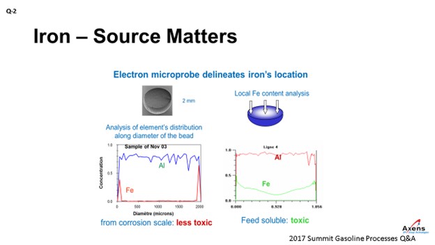
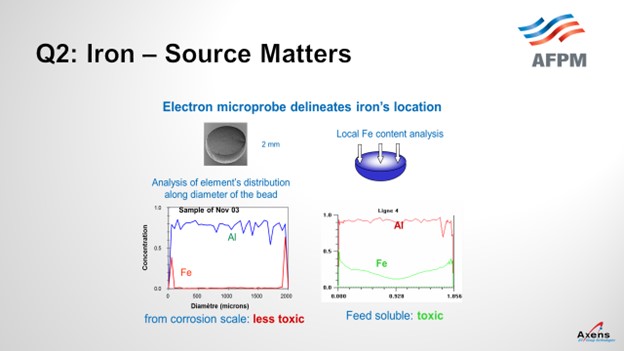
As mentioned, the first of the two types of iron we see is what we call atomic iron, which is based off metal content or due to heater tubes. It is a smaller iron particle. With atomic iron, we see a much higher penetration of iron into the center of the bead. This slide shows an electron microprobe of a catalyst. We would envision it this way with the left side being one side of the catalyst bead; the right side is the far edge with the center being the middle of the catalyst. What we see with atomic iron is that the iron penetrates much further into the core of the catalyst and is much more detrimental to the performances. Corrosion byproduct-based iron peaks on the left and right edges, which is equivalent to staying on the surface of the catalyst. So, this iron is less detrimental and not as impactful. It also has the impact of being iron from a corrosion byproduct. You can tolerate a much higher level of impurities – maybe up to 5,000 parts per million by weight (ppmw) – versus atomic iron where you see significant yield penalties starting at 1500 ppmw. So, the type of iron and the quantity of iron do make a big difference.
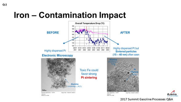
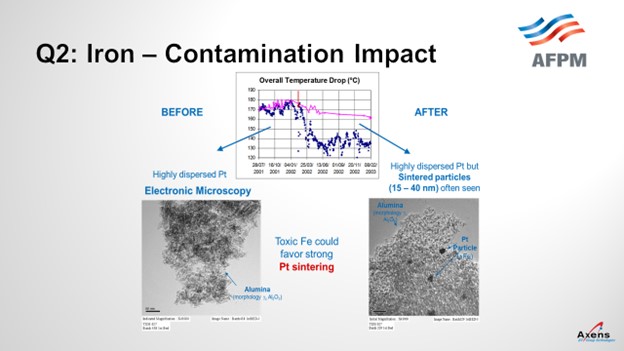
In terms of yields, what we have seen with iron penalties is the ΔT (delta T; temperature differential) of the unit. The total ΔT is shown in blue before and after an iron upset. What we saw was a 20 to 25% drop in total ΔT across the reformer due to the iron. This decrease in temperature observed corresponded with when we took electron microscopy of the catalyst before and after the event and saw platinum agglomeration within the core of the catalyst that was never able to be regained over the course of this cycle. It was a permanent loss of performance.
SUGG (Honeywell UOP)
Geoff covered a lot of the salient points. We also have many of the same sources identified in the past from different incidents of iron contamination. Another source of iron contamination we would like to highlight is that coming from new units. When the pre-commissioning activities – such as line flushing and cleaning – have been poorly executed or a significant time period has passed from the initial cleaning, there can be significant amounts of iron oxide transferred from the piping to the initial load of catalyst. On the subsequent loads of catalyst, we do not see that same accumulation. Other sources have been covered.
As far as impact, UOP has seen a lot of the same phenomenon that Geoff covered. One difference is that because semi-regen units regenerate less frequently than a CCR-type (continuous catalyst regeneration-type) unit which regenerates constantly, it seems like the semi-regen units are more tolerable to iron accumulation. Because without that continuous regeneration process that can drive the migration of iron into the middle of the pill, the catalyst in a semi-regen unit can accumulate much more iron than catalyst in CCR service can. However, we agree that once the iron penetrates the larger volume inside the pill, it will typically be a sign of reduced performance. If it cannot be stopped, then you will see catalyst performance continue to decline.
SHARON (Valero)
I do not really have much to add on this topic. It was covered well. We are just looking forward to continued innovation associated with iron contamination.
GEOFFREY DUBIN (Axens North America, Inc.)
As one of the permanent poisons affecting naphtha reforming catalyst, iron is very important to track throughout the catalyst’s life span. Iron, which affects the metal function of the catalyst, typically comes from three main sources:
-
Naphtha feed,
-
Metal dusting, and
-
Corrosion byproduct.
Naphtha feed-based iron is typically removed in the upstream hydrotreaters, but breakthrough of iron to the reformer can occur due to insufficient operating severity in the hydrotreater once the hydrotreater catalyst bed is saturated.
Metal dusting-based iron is derived from the fired heater tubes associated with excessive temperature when the reformer feed sulfur is too low, resulting in the removal of the sulfur passivation layer on the heater tube. This iron is then moved with the process fluid into the catalyst bed. The metal dusting process can also lead to heater tube ruptures, coke deposit within the reactor, and catalyst circulation difficulties for moving- bed type units.
Corrosion byproduct iron comes from corrosion scale from upstream equipment migrating downstream and depositing on the catalyst.
While there are three main sources of iron contamination, two of them – namely, naphtha feed-based iron and metal dusting-based iron – have increased impact due the atomic nature of the iron. Atomic iron is as named: individual atom(s) that are more mobile and able to penetrate deep into the catalyst pores. This atomic iron introduces a significant effect at lower concentrations than the corrosion scale iron which deposits on the outer surface of the catalyst.
The impact of iron on the catalyst is both a loss of selectivity, as well as a loss of activity, depending on the level of iron penetration and concentration. Unit performance is impacted primarily due to an increased difficult in redispersion of the platinum. The poor redispersion of platinum is a function of lower oxychlorination efficiency due to the interaction of iron with chlorides, as well as limiting the ability for hydrogen to access the platinum during the reduction step and for hydrocarbon access to the platinum during the operation due to the presence of the impurity. Additional side effects are often observed during iron poisoning and can include:
-
Reduced effective surface area caused by iron taking up “parking spots”, a situation that is compounded with the presence of other contaminants.
-
Higher sensitivity to sulfur.
-
Higher water generation during reduction due to iron reduction, which results in increased chloride removal and reduced acid function of the catalyst in the reactor section.
Impacts of iron contamination, as noted previously, are highly dependent on the type of iron and how it deposits on or within the catalyst. For surface iron derived from corrosion scale, concentrations as high of 5,000 ppmw have been observed with minor impacts on performance. Much lower concentrations of atomic iron, derived from metal dusting or feed sources, has been observed to cause performance and yield impacts at concentrations as low as 1500 ppmw.
Few options exist to mitigate iron contamination from the feed as the iron particles present are often in the micron range, which is typically below the trapping range of feed filtration. For metal dusting-derived iron, the use of a sulfur agent injection in the feed is often sufficient to minimize the risk. Corrosion scale type products should not make it past the feed filtration if the filter size mesh in the range of 10microns is used.
STEVE PHILOON (Honeywell UOP)
Honeywell UOP has identified three broad categories for the source of the iron that caused the contamination.
-
Poorly Cleaned New Construction: These are units where the catalyst quickly become contaminated with a relatively high level of iron. At some point, the initial load of catalyst is replaced, and the replacement load does not experience the same rapid accumulation of the contaminant iron. UOP is aware of many units with this experience, and the root cause has been identified as poor flushing and cleaning prior to the start of operations. The high level of iron oxide in the unit results in iron accumulation on the catalyst, contamination, and poor performance.
-
Contamination from Tankage: These are units that either continually, regularly, or occasionally feed the CCR Platforming™ unit from tankage and which experience either an accelerated continuous accumulation of iron or an “event” where there is a step change in the iron level on the catalyst. In these cases, the iron is frequently attributed to particulate corrosion products that have accumulated in the tank or corrosion in the tank and associated piping. It is suspected that poorly functioning gas blanketing systems may contribute to the problem in some of these cases.
-
Contamination from Other Sources: These are units that suffer either more rapid accumulation of iron on the Platforming catalyst than is normally seen or significant step changes over relatively short periods of time. There are many potential sources that have been hypothesized but not necessarily conclusively identified as a source of contamination in any unit.
-
Corrosion in a hydrotreating unit upstream of the Platforming unit: Particles of the corrosion products will become entrained in the hydrocarbon flow and carried into the catalyst bed in the Platforming reactors.
-
Poor pH control of the wash water in an upstream hydrotreating unit may deteriorate the iron sulfide layer, resulting in iron sulfide particles becoming entrained in the hydrocarbon flow.
-
Metals breakthrough from the hydrotreating unit reactor because the catalyst is saturated in metals: If this were the source of the iron contamination, we would generally expect to also see an increase in other contaminant metals on the Platforming catalyst in addition to the iron.
-
High-temperature carbon attack of the heater tubes in the Platforming unit heaters: The processes of carburization (metal dusting) and metal catalyzed coke formation will cause particles of the heater tube metal to break away from the tube surface and quickly transfer to the downstream reactor and catalyst bed. This phenomenon is more likely to occur in high-severity, low-pressure units or if there are hot spots on the heater tubes. There is also an increased risk immediately following installation of new heater tubes. This cause may be identified by a simultaneous increase in the level of chromium on the catalyst as the heater tubes are generally higher chrome steel.
-
Abrasion of metal from the lift lines may occur in CCR units where the superficial lift gas velocity is high, resulting in increased contact between catalyst pills and the walls of the lift pipes. Much of this material will be removed from the unit in the fines removal system, but some of the metal eroded from the pipe wall may remain on the outer surface of the catalyst pills.
From UOP’s experience with many operating Platforming units, there is a significant difference between semi-regen and CCR units in the level of iron contamination at which catalyst performance begins to be affected. Advanced analysis of multiple catalyst samples has shown that most of the iron initially accumulates on the outside surface of the catalyst pills where it has little, if any, impact on performance. At the conditions of regeneration, the iron will migrate into the inner surfaces of the pill and begin to affect the catalyst. As a result, semi-regen units can accept a significantly higher iron content before a change in behavior than would be true in CCR units.
Iron is generally thought of as a support modifier that will reduce the activity of the catalyst; although in some units, there also appears to be some impact on metal function. The iron may impede the adsorption of chloride and may also trap sulfur on the catalyst as iron sulfide. Units with significant iron contamination could see reformate yield loss and need to operate at somewhat higher temperatures to maintain product quality.
Once the iron has penetrated the inner surfaces of the catalyst pills, there is little that can be done. In CCR units, it may be possible to reduce the rate of diffusion of the iron into the pills by maintaining good operation of the regeneration section burn zone and oxychlorination zone. It is important to maintain good control of the peak burn-zone temperature, but the migration of iron will happen, to some extent, at the conditions of the regeneration.
Based on the explanation above, Best Practice is to prevent or minimize the rate of accumulation of iron on the catalyst. Regular monitoring of the rates of corrosion in the naphtha hydrotreating unit upstream of the Platforming units is important, and prompt action should be taken when there is evidence of corrosion. For CCR Platforming units, the catalyst should regularly be sent for analysis of iron and other contaminant metals by the catalyst vendor so that the rate of iron accumulation can be tracked. If the rate of accumulation is excessive, the source should be identified, and corrective action taken.
Year
2017
Process
Question 3: What are your Best Practices for unloading solid phosphoric acid (SPA) catalyst from a catalytic polymerization unit, and what safety issues do they address?
KINDERMAN (Clariant Corporation)
The Best Practices for unloading solid phosphoric acid catalyst from a cat-poly unit include neutralization using hydrocarbon-free nitrogen, performing a pulse purse with nitrogen, and then releasing it through the bottom of the reactor. It is relatively simple unless there is some caking or building up of a solid material. The pH can be neutralized with soda ash if water drilling is used. Tarps are placed around the bottom of the catalyst to collect the fines if they come out in dust and scatters. That is the simple answer of how to unload the reactor.
SHARON (Valero)
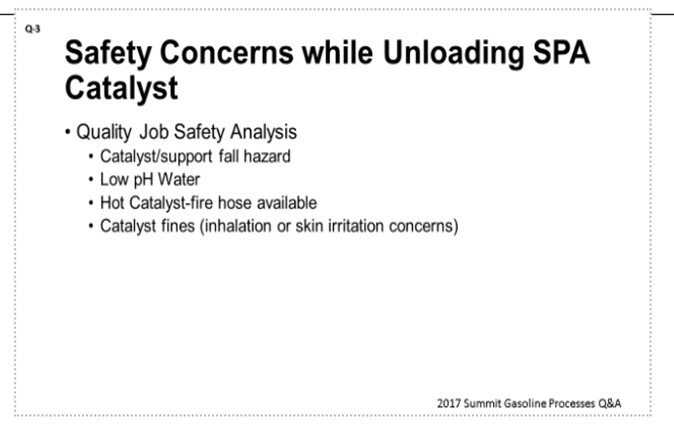
From our perspective, the most important piece is really to do a quality JSA (Job Safety Analysis). That is what you want to knock out first. Bryan touched on quite few Best Practices, so I will just add a couple additional important safety procedures. One is that because you have the catalyst/support fall hazard, you will want to barricade about 150 feet around it and maintain limited access inside that barricade. Since you have the low pH runoff issue, you will want to have sodium carbonate available to neutralize any low pH material or excess water. Also, be prepared to contain the run-off material to avoid off-site impacts. Additionally, there is hot catalyst present which can auto-oxidize or glow a little. Be prepared to wet the catalyst; and again, be prepared for low pH runoff. Lastly, you have the catalyst fines, which are inhalation and skin irritation concerns, thereby necessitating the installation of the canvas curtain at the base of the reactor to protect personnel from dust.
SABITOV (Phillips 66)
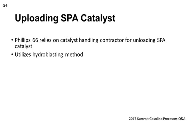
I think we still have one and a half units in operation, so we typically rely on the catalyst-loading contractor for handling catalyst. As far as I know, they are using a hydro-blasting method.
HEIDI FRASER (Honeywell UOP)
There are two types of Honeywell UOP Cat Poly reactors: chamber and tubular. Each has different unloading concerns, and there are several different unloading options available for each.
Chamber Reactors
The basic method is to remove the locking pins from the bottom support plate and allow the catalyst from the bottom bed to drop out of the reactor by gravity. After the bottom catalyst bed has dropped and been shoveled out of the collection bin at the base of the reactor, the locking pins for the next support bed are released and the grid can fall so that the next bed of catalyst will drop out of the reactor. Continue unloading one bed at a time. However, if the pressure drop across the reactor was allowed to get too high during the catalyst run, the catalyst will be coked up and/or carbon-fused together and will not drop. This is most common in the bottom bed as the pressure drop will be highest at this point: The higher the pressure drops, the more difficulty there will be unloading. In such an event, it becomes extremely difficult and dangerous to enter the reactor to break up the catalyst. The bridged catalyst could collapse and bring the person in the reactor into danger. As a result, alternate methods have been developed.
In water drilling or hydroblasting, the catalyst can be removed by cutting holes through the bed from the bottom using a high-pressure, low-volume water lance. This technique is helpful if the catalyst bed has partially dropped but the remaining catalyst is bridged. Cutting holes in the catalyst may break up the bridge and allow the remainder of the catalyst to fall. If the catalyst still does not fall, open the manway above the bed and use short bursts of fire water directed at the catalyst to remove the remaining catalyst. Only one manway should be opened at a time to prevent air from circulating through the spent catalyst. The oxygen could react with the tar on the catalyst to produce carbon monoxide. Another disadvantage of this method is that the water reacts with the SPA catalyst and becomes corrosive. Use no more water than is needed. Runoff should be neutralized with sodium carbonate or calcium carbonate to reduce its acidity.
In pressuring out the catalyst with steam, as each grid is released, a steam line is connected to the quench connection above the bed to be unloaded. This approach allows the pressure in the void space above the catalyst to build up gradually to pressure the catalyst out the opening rather than relying on gravity. This approach is more effective for catalyst beds that are solidly coked up so that the pressure can build in the void space. A variation calls for opening the grids and then bracing the bottom head closed while the reactor is pressured up with steam to 5 to 7 psig (pounds per square inch gauge). Then the brace is removed remotely, and the catalyst is expelled violently. These methods eliminate the need for a person to enter the reactor to break up the fused catalyst to start catalyst flowing but will result in a great deal of dust in the area. Both are described in the UOP General Operating Manual.
The controlled detonation technique uses small explosive charges to dislodge the catalyst so it will drop out the bottom manway. The intent is not to use charges with such size as to force the catalyst from the reactor; but rather, to break up the solidified catalyst mass into smaller pieces that are easier to dislodge. This approach was developed by a Texas company and has not been quantitatively analyzed by UOP, so it is not officially recommended. However, we are aware that many of our North American customers routinely use this technique successfully. There have been some reports of damage to the grid screens from shrapnel from the conduits to which the explosives are taped. There has also been some concern about stress on the reactor vessel from the explosions, but no damage has been reported to a reactor vessel so far, including cracking or bulging, except the grid screens. This method is much quicker and more effective at emptying the catalyst from the reactor but results in a great deal of dust in the area.
The vacuuming and CARDOX technique were introduced by one of the catalyst handling companies and is a cleaner system. Catalyst is vacuumed from the top bed downward. The support grids will only be opened after all catalyst has been removed from the bed above. If the catalyst is agglomerated, it cannot be removed by vacuuming only. The catalyst could be broken up with small jackhammers. If the catalyst is tightly sintered together, CARDOX would be used to break it apart. CARDOX is a modern blasting device that uses CO2 for dislodging coal and other mining materials. The CO2 is released under pressure from cylinders drilled into the catalyst bed. The explosive discharge (like a fire extinguisher) breaks up the catalyst. CO2 is a non-supporter of combustion. During the unloading step, the reactor is kept under a nitrogen blanket to prevent dust explosions. The benefits claimed by this method are that there is no dust or corrosive water to clean up, so the work area is cleaner.
Tubular Reactors
Tubular reactors can be unloaded using either dry or wet drilling. The reactor tubes are drilled individually from the top using an air-driven turbine drill. Different augers or bits may be required to drill the catalyst out of the tubes. Dry drilling requires a catalyst collection system and may have trouble in gummy spots. Cold water in the jacket helps to harden the gummy spot and allow it to be drilled out more easily. Care must be taken to be certain that the tubes are clean, especially in those sticky spots. Some refiners have reported signs of etching in the tubes from dry drilling.
Use of a wet drill is typically better than a dry drilling at removing all deposits, and a cold shell also enables better catalyst removal. The disadvantage is that a considerable amount of acidic water is created from the reaction of the water with the SPA catalyst fines. Runoff should be neutralized with sodium carbonate or calcium carbonate to reduce its acidity. Some units have experienced corrosion in the lower part of some tubes. It may be that water is getting into undrilled tubes.
Both methods require that reactor tubes should be cleaned with an air-driven wire brush to remove any remaining catalyst, scale, or coke deposits. Catalyst fines should be cleaned from all exposed surfaces to prevent corrosion.
Year
2017
Process
Question 4: For the isomerization unit, what is your treatment for the streams containing high concentrations of hydrochloric acid (HCl) in the reactor emergency depressurization system?
SUGG (Honeywell UOP)
Currently, UOP does not include treatment of gas from the reactor effluent as it enters the flare header using the emergency depressuring system in our Penex™ or Butamer™ process unit designs. So, depressuring to flare with a highly concentrated hydrogen chloride stream is not to be taken lightly, due to possible corrosion in the flare system because the flare headers are typically wet. Prior to depressuring the reactors to flare, steps should be taken by Operations personnel to minimize the volume of gas to flare. One of these steps is to decrease the reactor section pressure down to that just above the net gas scrubber pressure through the stabilizer scrubber so that the amount of acidic gas being sent to the flare is kept at a minimum.
Further, upon completion of the depressuring step, UOP recommends following the depressuring with the dry gas purge – preferably nitrogen – to sweep the acid gases from the flare system. During or after purging with nitrogen, it is recommended to drain low-point drains in the section of the flare header where acidic-free water can collect and cause corrosion. For Penex and Butamer™ units, experience has shown that extensive corrosion has not occurred in the flare system with the procedures and guidelines provided. UOP is aware of an isolated incident in which a customer reported significant corrosion to its common flare header section. But after changes in the customer’s procedures and changes to the physical layout of their flare header system, the corrosion was no longer reported.
SABITOV (Phillips 66)
At Phillips, we have two types of the isomerization units, with respect to the hydrogen circuit configuration. The unit shown on the left side of the slide is a recycle gas unit, and the unit on the right is a hydrogen once-through unit. The recycle gas units will depressure the reactors from the separator either through the off-gas scrubber, as shown here on the slide, or they can depressure directly to the flare header. The hydrogen once-through units will depressure through the off-gas scrubber via the stabilizer. They also have an option of depressuring directly to the flare header through the emergency depressuring line at the reactor outlet.
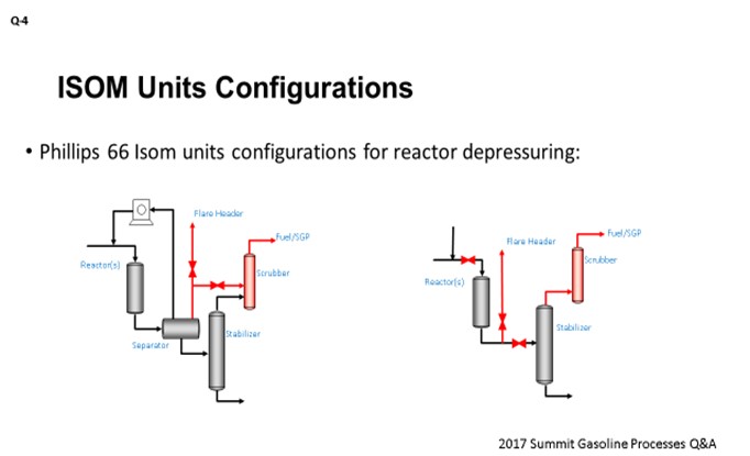
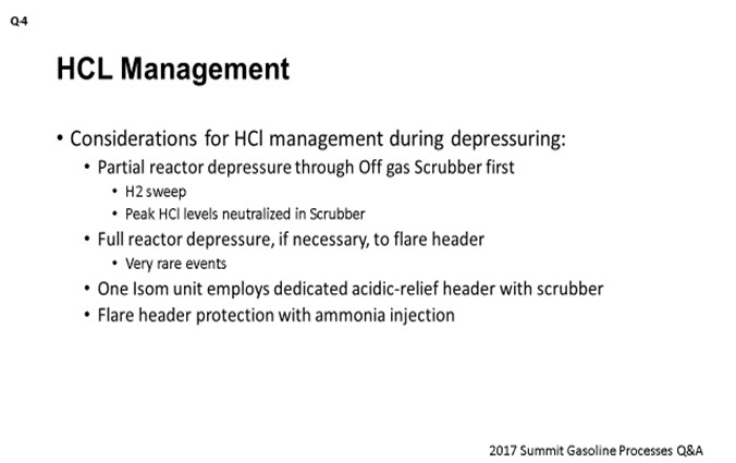
For those units where we use chloride alumina catalyst, you obviously have a very high HCl concentration in the reaction zone. The following considerations would apply: The initial partial reactor depressuring should be performed through the off-gas scrubber down to the pressure of the off-gas destination, which could be set either by the fuel gas header or by a saturated gas plant. This depressuring can be accompanied with the reactor hydrogen sweep. Overall, this step enables neutralization of the peak HCl levels in the scrubber. If full reactor depressure is required due to the continuing runaway situation, then reactors should be depressured to the flare header. In this case, some ingress of the HCl to the flare header might be possible. I should say that those are rare events in our units; and typically, the initial partial reactor depressure is efficient enough to stop a runaway situation. Having said that, we do have one C4 isomerization unit that was built with the provision of the reactor depressure to the dedicated acid relief header, and which is equipped with its own scrubber. Also, if necessary, our refineries can protect their flare headers with the ammonia injection during the isomerization reactor depressuring events.
DUBIN (Axens North America)
We do not have much to add. Those were two very good answers from Patrick and Alex. Axens’ approach is to go through the scrubber system to depressurize directly in there and then into the caustic scrubbing. The one item that we do want to point out is to make sure that the valve systems are protected from an acidic environment so that they are functional when the emergency does arrive.
RAÚL ROMERO (Nalco Energy Services)
My question is about the potential soil deposits that occur when you are neutralizing with ammonia in a header going into the flare system. That is typically trying to keep that as clean as possible to ensure a free passing to the flare.
SABITOV (Phillips 66)
Yes. I guess formation of the ammonium chloride would probably be possible at the right sublimation conditions. We have not really seen any big issues with salt formation. Again, the events of the full depressure are extremely rare, so that does not seem to be presenting any practical problem.
JOCELYN DAGUIO (Honeywell UOP)
Honeywell UOP does not include treatment of gas from the reactor effluent as it enters the flare header when using the emergency depressuring system in our Penex™ and Butamer™ process unit designs.
Depressuring to flare with a highly concentrated HCl stream is not to be taken lightly due to possible corrosion to the flare system because flare headers are typically wet. Just prior to depressuring the reactors to flare, steps should have been taken by Operations personnel. One such step is to decrease the reactor section pressure just slightly above the net gas scrubber pressure through the stabilizer scrubber so that the amount of acidic gas sent directly to the flare is kept at a minimum.
Further, upon completion of the emergency depressuring to flare, UOP recommends following the depressuring with a dry gas purge – preferably dry nitrogen – to remove HCl from the flare system. During or after purging with dry nitrogen, it is recommended to drain low point drains in sections of the flare header where acidic-free water can collect and cause corrosion to the flare header and associated piping.
GEOFFREY DUBIN (Axens North America, Inc.)
Axens recommends that in cases of emergency depressurization of the reactor circuit, the circuit fluid be depressurized into the product stabilizer with the light gases still being treated in the off-gas caustic scrubber. It should be noted that care should be taken to protect safety valves in the reactor circuit to prevent corrosion of the valve and subsequent loss of relief capabilities.
Year
2017
Process
Question 5: Is the presence of pyrophoric compounds common in feed/effluent exchangers? What neutralization methods do you employ prior to exposing the equipment to the atmosphere?
SABITOV (Phillips 66)
I would like to start by saying that reforming units operate with very low sulfur levels. Typically, reformer feed sulfur is less than one ppm (part per million). Therefore, reformers would fall under the area of low-risk units, with respect to the presence of pyrophoric compounds, compared to, say, hydrotreaters. If we see any issues with pyrophoric compounds, they would be typically encountered more when handling spent catalyst or spent catalyst dust such as the CCR dust collector product.
We did a survey of our sites; and in general, our reformers do not really have issues with pyrophoric compounds in their combined feed effluent exchangers during turnarounds. The same survey also showed that we seem to have two groups of units. The so-called clean units just go ahead and open their CFEs (combined feed exchangers) after conventional nitrogen sweep; so, really no issues. And then, we have the other group of units where they do see black sludge on the effluent side of the CFEs. That material typically represents some mix of PNAs (polynuclear aromatics), ammonium chloride salts, catalyst dust, iron scale, and potentially iron sulfide. The key for handling those cases is to be aware of the pyrophoric component presence. If a preventative action is needed, wetting those deposits with water would be a basic mitigation technique.

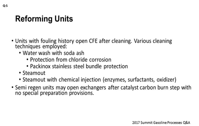
Those units with a history of the exchanger fouling would open their exchangers for turnaround only after performing the cleaning step. Therefore, the risk of pyrophoric material is greatly reduced. We use various cleaning techniques for the exchangers. For those exchangers that can potentially be sensitive to the chloride corrosion attack (such as a Packinox stainless steel bundle), we do a water-wash with the soda ash solution to neutralize the chlorides before those exchangers can be open to the atmosphere. Low-alloy or carbon-steel CFEs have been steamed out or cleaned using a combination of steam and the chemical injection, which is basically a mix of enzymes, surfactants and the oxidizers. I should note that after those cleaning steps, there have been many cases where we still have observed PNAs on the effluent side. Typically, a separate aromatic solvent circulation would be required to remove those PNAs. Our semi-regen units typically open up CFEs after the carbon-burn step of the catalyst regeneration and really do not make any special cleaning provisions for opening.
SHARON (Valero)
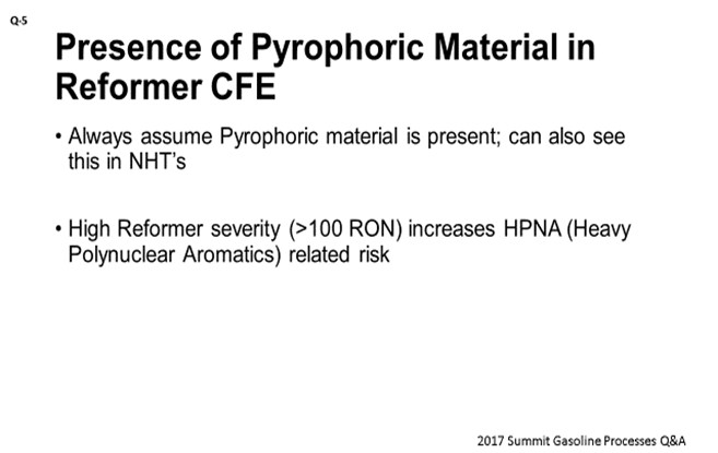
Alex answered this question well. Our experience is similar, so I just want to add a few points. As Alex said, you should always assume pyrophoric material is present. We concur with Alex’s statement that you can also primarily see these materials in hydroprocessing units. Also, the higher the severity, the higher the risk of HPNAs (heavy polynuclear aromatics) being present.
SUGG (Honeywell UOP)
This question could also be about the naphtha hydrotreater unit’s feed effluent exchanger. On this topic, it is generally sufficient to water-wash the hydrotreater feed-effluent exchanger prior to exposure to air. However, if there is a concern or a previous history with iron sulfide fires, we know of others in the industry who have used methods that include strong oxidizers such as potassium permanganate, percarbonate, and peroxymonosulfate. A qualified cleaning contractor experienced in this work could provide more details. I think the rest of it has been covered.
STEVE PHILOON (Honeywell UOP)
In 2015, UOP led a Principles & Practices session on the topic of NHT (naphtha hydrotreater) and reforming unit feed/effluent exchanger fouling and cleaning.
In Honeywell UOP Platforming™ units of both CCR and SR types, the feed/effluent exchanger or combined feed exchanger (CFE) is generally a clean service. There are occasionally problems with feed-side fouling due to peroxide gums, coke or iron scale, or reactor effluent-side fouling due to ammonium chloride salts or polynuclear aromatic compounds. It is uncommon to have problems with pyrophoric compounds (most typically iron sulfide) in CFEs. In principle, it is possible for corrosion products and iron sulfide scale to collect in low flow areas of the combined feed exchanger and be a hazard when exposed to air during maintenance. However, in many units, the CFE is washed with water to remove salts before the exchanger is opened to the air. Water does not prevent iron sulfide from reacting with oxygen, but it does reduce the rate of mass transfer so that the rate of reaction is slowed to the point that the exchanger can be opened, and the material removed before a problem occurs. Also, in semi-regen units, a coke burn is generally done before the unit is opened for maintenance. While this does not remove all of the iron sulfide, it may reduce its concentration.
Note that the most common location of problems with pyrophoric material in CCR units is with the dust removed from fines removal system. Both semi-regen and CCR-type units may experience problems with pyrophoric material during catalyst unloading. That said, UOP is aware of one instance where a fire occurred as the bottom head of a vertical combined feed exchanger was dropped. The refinery reported that hydrocarbon was present due to plugged drain lines, and it suspected that ignition was provided by pyrophoric material. The fire was quickly extinguished without any injuries or significant equipment damage.
NHT units, like all other hydrotreating units, are units where exchanger fouling issues are more common. The feed side of the feed/effluent exchanger may become fouled with peroxide gums or corrosion products from tankage or upstream units. The reactor effluent side may become fouled with ammonium salts, particularly if feeds high in nitrogen are being processed. Because of the presence of sulfur and iron, there is always a concern about pyrophoric iron. When a feed/effluent exchanger train is to be opened for cleaning or other service, it is generally sufficient to water-wash the exchanger prior to changing the environment to air. The wash procedure will easily remove salts and other debris, and the water will provide a layer that reduces the rate of oxygen diffusion and therefore limits the rate of the iron sulfide oxidation reaction. If there is a concern or previous history with iron sulfide fires, over the years, the refining and petrochemical industries have used many methods to treat pyrophoric iron sulfide with various chemicals including strong oxidizers, such as potassium permanganate, percarbonate and peroxymonosulfate. The heat exchanger vendor and the exchanger cleaning contractor may be able to provide a detailed procedure.
Year
2017
Process