Question 2: Iron is one of the most common contaminant metals seen on naphtha reforming catalyst. What is the source, what is the impact to yields and operation, and what can be done to mitigate these effects?
DUBIN (Axens North America)
This is a three-part question, so we will try and take it step-by-step. The three main sources we see for iron poisoning of catalyst are from the naphtha feed the hydrocarbon itself metal dusting, and corrosion byproducts. With the naphtha feed, this poisoning is often due to inadequate hydrotreating conditions in the upstream hydrotreater. Or if your hydrotreating catalyst is saturated with metals, you can see some metal slip that will make it into the downstream reformer. Metal dusting is related to removal of the sulfur passivation layer in your heater tubes. This contamination is a problem for moving bed-type reformers, but high temperatures with very low sulfur feeds can elute the iron sulfide off the tube and downstream. And then, the last source is corrosion byproduct, which is very much like it says: corrosion issues from upstream, or wherever else in the plant, that find their way to the reformer.
The impacts these poisoning events lead to are dependent on the type of iron that makes it into the reformer catalyst. The main impacts are generally selectivity and activity, and they are due to a limitation in the redispersion of platinum during the regeneration steps. During oxychlorination, there is an interaction of iron and chlorides that can limit the redistribution. Also, during reduction, hydrogen is blocked from accessing the catalyst pores preventing the system from properly reducing the catalyst. Or during normal operation, hydrocarbon feed is blocked out from accessing the full catalyst performance.
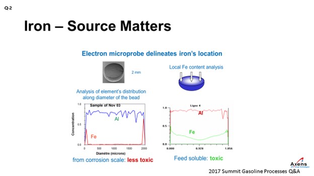
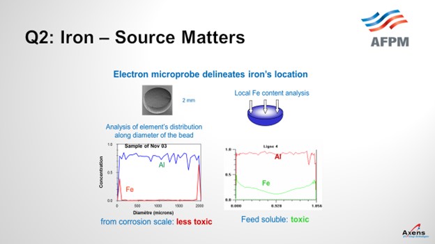
As mentioned, the first of the two types of iron we see is what we call atomic iron, which is based off metal content or due to heater tubes. It is a smaller iron particle. With atomic iron, we see a much higher penetration of iron into the center of the bead. This slide shows an electron microprobe of a catalyst. We would envision it this way with the left side being one side of the catalyst bead; the right side is the far edge with the center being the middle of the catalyst. What we see with atomic iron is that the iron penetrates much further into the core of the catalyst and is much more detrimental to the performances. Corrosion byproduct-based iron peaks on the left and right edges, which is equivalent to staying on the surface of the catalyst. So, this iron is less detrimental and not as impactful. It also has the impact of being iron from a corrosion byproduct. You can tolerate a much higher level of impurities – maybe up to 5,000 parts per million by weight (ppmw) – versus atomic iron where you see significant yield penalties starting at 1500 ppmw. So, the type of iron and the quantity of iron do make a big difference.
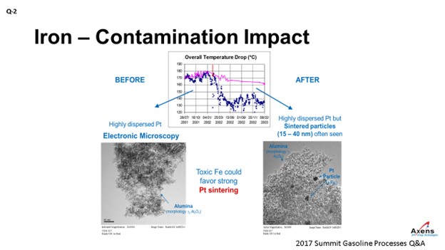
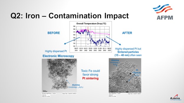
In terms of yields, what we have seen with iron penalties is the ΔT (delta T; temperature differential) of the unit. The total ΔT is shown in blue before and after an iron upset. What we saw was a 20 to 25% drop in total ΔT across the reformer due to the iron. This decrease in temperature observed corresponded with when we took electron microscopy of the catalyst before and after the event and saw platinum agglomeration within the core of the catalyst that was never able to be regained over the course of this cycle. It was a permanent loss of performance.
SUGG (Honeywell UOP)
Geoff covered a lot of the salient points. We also have many of the same sources identified in the past from different incidents of iron contamination. Another source of iron contamination we would like to highlight is that coming from new units. When the pre-commissioning activities – such as line flushing and cleaning – have been poorly executed or a significant time period has passed from the initial cleaning, there can be significant amounts of iron oxide transferred from the piping to the initial load of catalyst. On the subsequent loads of catalyst, we do not see that same accumulation. Other sources have been covered.
As far as impact, UOP has seen a lot of the same phenomenon that Geoff covered. One difference is that because semi-regen units regenerate less frequently than a CCR-type (continuous catalyst regeneration-type) unit which regenerates constantly, it seems like the semi-regen units are more tolerable to iron accumulation. Because without that continuous regeneration process that can drive the migration of iron into the middle of the pill, the catalyst in a semi-regen unit can accumulate much more iron than catalyst in CCR service can. However, we agree that once the iron penetrates the larger volume inside the pill, it will typically be a sign of reduced performance. If it cannot be stopped, then you will see catalyst performance continue to decline.
SHARON (Valero)
I do not really have much to add on this topic. It was covered well. We are just looking forward to continued innovation associated with iron contamination.
GEOFFREY DUBIN (Axens North America, Inc.)
As one of the permanent poisons affecting naphtha reforming catalyst, iron is very important to track throughout the catalyst’s life span. Iron, which affects the metal function of the catalyst, typically comes from three main sources:
-
Naphtha feed,
-
Metal dusting, and
-
Corrosion byproduct.
Naphtha feed-based iron is typically removed in the upstream hydrotreaters, but breakthrough of iron to the reformer can occur due to insufficient operating severity in the hydrotreater once the hydrotreater catalyst bed is saturated.
Metal dusting-based iron is derived from the fired heater tubes associated with excessive temperature when the reformer feed sulfur is too low, resulting in the removal of the sulfur passivation layer on the heater tube. This iron is then moved with the process fluid into the catalyst bed. The metal dusting process can also lead to heater tube ruptures, coke deposit within the reactor, and catalyst circulation difficulties for moving- bed type units.
Corrosion byproduct iron comes from corrosion scale from upstream equipment migrating downstream and depositing on the catalyst.
While there are three main sources of iron contamination, two of them – namely, naphtha feed-based iron and metal dusting-based iron – have increased impact due the atomic nature of the iron. Atomic iron is as named: individual atom(s) that are more mobile and able to penetrate deep into the catalyst pores. This atomic iron introduces a significant effect at lower concentrations than the corrosion scale iron which deposits on the outer surface of the catalyst.
The impact of iron on the catalyst is both a loss of selectivity, as well as a loss of activity, depending on the level of iron penetration and concentration. Unit performance is impacted primarily due to an increased difficult in redispersion of the platinum. The poor redispersion of platinum is a function of lower oxychlorination efficiency due to the interaction of iron with chlorides, as well as limiting the ability for hydrogen to access the platinum during the reduction step and for hydrocarbon access to the platinum during the operation due to the presence of the impurity. Additional side effects are often observed during iron poisoning and can include:
-
Reduced effective surface area caused by iron taking up “parking spots”, a situation that is compounded with the presence of other contaminants.
-
Higher sensitivity to sulfur.
-
Higher water generation during reduction due to iron reduction, which results in increased chloride removal and reduced acid function of the catalyst in the reactor section.
Impacts of iron contamination, as noted previously, are highly dependent on the type of iron and how it deposits on or within the catalyst. For surface iron derived from corrosion scale, concentrations as high of 5,000 ppmw have been observed with minor impacts on performance. Much lower concentrations of atomic iron, derived from metal dusting or feed sources, has been observed to cause performance and yield impacts at concentrations as low as 1500 ppmw.
Few options exist to mitigate iron contamination from the feed as the iron particles present are often in the micron range, which is typically below the trapping range of feed filtration. For metal dusting-derived iron, the use of a sulfur agent injection in the feed is often sufficient to minimize the risk. Corrosion scale type products should not make it past the feed filtration if the filter size mesh in the range of 10microns is used.
STEVE PHILOON (Honeywell UOP)
Honeywell UOP has identified three broad categories for the source of the iron that caused the contamination.
-
Poorly Cleaned New Construction: These are units where the catalyst quickly become contaminated with a relatively high level of iron. At some point, the initial load of catalyst is replaced, and the replacement load does not experience the same rapid accumulation of the contaminant iron. UOP is aware of many units with this experience, and the root cause has been identified as poor flushing and cleaning prior to the start of operations. The high level of iron oxide in the unit results in iron accumulation on the catalyst, contamination, and poor performance.
-
Contamination from Tankage: These are units that either continually, regularly, or occasionally feed the CCR Platforming™ unit from tankage and which experience either an accelerated continuous accumulation of iron or an “event” where there is a step change in the iron level on the catalyst. In these cases, the iron is frequently attributed to particulate corrosion products that have accumulated in the tank or corrosion in the tank and associated piping. It is suspected that poorly functioning gas blanketing systems may contribute to the problem in some of these cases.
-
Contamination from Other Sources: These are units that suffer either more rapid accumulation of iron on the Platforming catalyst than is normally seen or significant step changes over relatively short periods of time. There are many potential sources that have been hypothesized but not necessarily conclusively identified as a source of contamination in any unit.
-
Corrosion in a hydrotreating unit upstream of the Platforming unit: Particles of the corrosion products will become entrained in the hydrocarbon flow and carried into the catalyst bed in the Platforming reactors.
-
Poor pH control of the wash water in an upstream hydrotreating unit may deteriorate the iron sulfide layer, resulting in iron sulfide particles becoming entrained in the hydrocarbon flow.
-
Metals breakthrough from the hydrotreating unit reactor because the catalyst is saturated in metals: If this were the source of the iron contamination, we would generally expect to also see an increase in other contaminant metals on the Platforming catalyst in addition to the iron.
-
High-temperature carbon attack of the heater tubes in the Platforming unit heaters: The processes of carburization (metal dusting) and metal catalyzed coke formation will cause particles of the heater tube metal to break away from the tube surface and quickly transfer to the downstream reactor and catalyst bed. This phenomenon is more likely to occur in high-severity, low-pressure units or if there are hot spots on the heater tubes. There is also an increased risk immediately following installation of new heater tubes. This cause may be identified by a simultaneous increase in the level of chromium on the catalyst as the heater tubes are generally higher chrome steel.
-
Abrasion of metal from the lift lines may occur in CCR units where the superficial lift gas velocity is high, resulting in increased contact between catalyst pills and the walls of the lift pipes. Much of this material will be removed from the unit in the fines removal system, but some of the metal eroded from the pipe wall may remain on the outer surface of the catalyst pills.
From UOP’s experience with many operating Platforming units, there is a significant difference between semi-regen and CCR units in the level of iron contamination at which catalyst performance begins to be affected. Advanced analysis of multiple catalyst samples has shown that most of the iron initially accumulates on the outside surface of the catalyst pills where it has little, if any, impact on performance. At the conditions of regeneration, the iron will migrate into the inner surfaces of the pill and begin to affect the catalyst. As a result, semi-regen units can accept a significantly higher iron content before a change in behavior than would be true in CCR units.
Iron is generally thought of as a support modifier that will reduce the activity of the catalyst; although in some units, there also appears to be some impact on metal function. The iron may impede the adsorption of chloride and may also trap sulfur on the catalyst as iron sulfide. Units with significant iron contamination could see reformate yield loss and need to operate at somewhat higher temperatures to maintain product quality.
Once the iron has penetrated the inner surfaces of the catalyst pills, there is little that can be done. In CCR units, it may be possible to reduce the rate of diffusion of the iron into the pills by maintaining good operation of the regeneration section burn zone and oxychlorination zone. It is important to maintain good control of the peak burn-zone temperature, but the migration of iron will happen, to some extent, at the conditions of the regeneration.
Based on the explanation above, Best Practice is to prevent or minimize the rate of accumulation of iron on the catalyst. Regular monitoring of the rates of corrosion in the naphtha hydrotreating unit upstream of the Platforming units is important, and prompt action should be taken when there is evidence of corrosion. For CCR Platforming units, the catalyst should regularly be sent for analysis of iron and other contaminant metals by the catalyst vendor so that the rate of iron accumulation can be tracked. If the rate of accumulation is excessive, the source should be identified, and corrective action taken.