Question 2: Please discuss your experience regarding the need to add an emergency shutdown (ESD) valve between the cold high pressure separator and the product stripper. The typical design for vapor blow through is to size the stripper relief valve for this case.
Vern Mallett (UOP)
UOP considers that an ESD valve between the cold separator and product stripper is not required and not recommended. The design philosophy behind this practice is to prevent liquid from filling the cold high pressure separator and carrying over into the auto depressuring system and filling the relief header. Once the liquid has filled the depressuring line to the relief header, and if the auto depressuring system were actuated, there is a possibility of damaging the depressuring system and relief lines.
However, some UOP customers require such an ESD valve, which UOP will incorporate into the design of the particular unit. When an ESD valve is specified instrumentation is designed for the ESD valve that will allow the valve close on low level as intended, and then to be reset once the level of the cold high pressure separator reaches approximately 10% of scale above the low level trip set point.
UOP’s philosophy is that the code requires that the downstream flash drum be provided with a properly sized relief valve to handle the loss of level in the upstream drum. Since we have the relief valve at the downstream vessel sized for the loss of level, a cutoff valve in the hydrocarbon line from the high pressure vessel is not going to provide any more protection. In addition, it introduces an additional failure mode that is undesirable. Often such cutoff valve systems are set up with manual reset. Therefore if a low level (or just a system failure) causes the valve to shut, then it is likely that the separator will overflow because the operator may not have time to go out and reset the solenoid valve (or find out what failed and get the valve open again) before the separator overflows. When that happens, the separator and recycle gas line will fill up with liquid and eventually shutdown the recycle gas compressor. At this point the unit is not safe. If it is desired to depressure the unit it will not be possible because the separator and piping to the depressuring system will be full of liquid and therefore the depressurizing capability is lost. The downstream vessel s already protected according to the code. Therefore UOP does not recommend a cutoff valve at the separator
The downstream stripper should have a relief valve that will be sized for the loss of level case per the requirements of the code. The only issue is the location of the relief valve. In order to avoid tray damage on loss of level, the relief valve could be located at the feed tray.
Michael Chuba (Sunoco)
Although this needs to be evaluated on a case by case basis, general practice has been to properly size the relief valve protecting downstream equipment based on the blow through scenario. Doing this eliminates the need for a separate emergency shutdown (ESD) valve between the high pressure separator and the downstream lower pressure rated equipment. If the relief valve is not adequately sized, at a minimum a high pressure protection system or HIPPS system would have to be installed. The HIPPS system is a safety instrumented system (SIS) that would have to be designed with a reliability equal to or greater than that of a pressure relief valve. Thus, the safety integrity level (SIL) of this system could be as high as three or greater. Because the control is on level and the potential fouling nature of the material in these vessels, designing a SIL 3 type interlock is very difficult. Therefore, the preferred approach is to ensure that the CV of the letdown control valve and its bypass valve match the RV of the downstream equipment.
To assist in operation and control of the level in the high pressure separators most recently designed or modified separators are equipped with independent transmitters for High and Low level alarms. In addition LOPA analysis typically finds that an additional independent high level interlock switch is required to trip the recycle compressor if a separate KO drum is not present.
Alan Leute (El Paso Refinery)
For typical Hydrotreaters (up to nominal 1000 psi Separator pressure), we design the Stripper overhead relief valve to handle blow through of hydrogen/vapor from total loss of level in the Separator(s).
There may be additional concerns with this for high pressure Hydrotreaters (greater than 1500 psi Separator pressure) and hydrocrackers, but Western Refining does not have any of these units.
Question 5: Does anyone have proven experience using promoted zinc oxide products for sulfur removal upstream of the reforming section? What improvement have you measured in the downstream catalyst performance?
Brian Moyse (Haldor Topsoe)
Topsoe has installed our new promoted zinc oxide product HTZ-51 upstream the reformer section in a number of Ammonia, Hydrogen and Methanol plants. Topsoe’s promoted zinc oxide is also used as a purification absorbent upstream methanator units.
Our promoted zinc oxide product HTZ-51 provides:
•Improved sulphur uptake
•Increased Hydrogenation activity for inorganic sulfur compounds
These benefits will offer the downstream catalyst the best performance and an increase in lifetime as they are protected from both inorganic and organic sulphur.
It can be difficult to get the necessary data from the steam reforming section to verify the benefit of using a promoted ZnO, but we have good data from a purification unit, using HTZ-51 upstream a methanation unit, which clearly shows that HTZ-51 made a big difference. The operating temperature and process conditions are very similar to the conditions upstream a steam reforming application.
The methanation catalyst is also a Ni containing catalyst as is both the pre-reformer and reformer catalyst. The benefits described below will thus be similar to those obtained for pre-reforming and reforming catalysts.
Prior to installing a Topsoe promoted zinc oxide a plant was operating with a non-promoted zinc oxide upstream the methanation catalyst. The plot in Figure 1 clearly indicates that there is a severe deactivation of the methanation catalyst as indicated by the fall in temperature across the bed. Both the non-promoted zinc oxide absorbent and the methanation catalyst were changed out frequently.
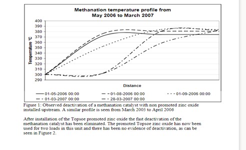
Figure 1: Observed deactivation of a methanation catalyst with non promoted zinc oxide installed upstream. A similar profile is seen from March 2005 to April 2006.
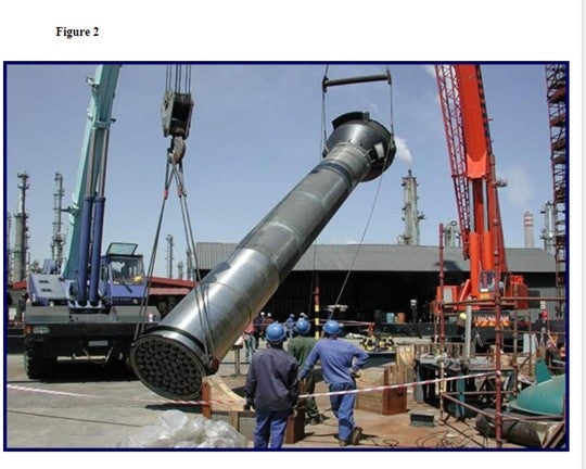
After installation of the Topsoe promoted zinc oxide the fast deactivation of the methanation catalyst has been eliminated. The promoted Topsoe zinc oxide has now been used for two loads in this unit and there has been no evidence of deactivation, as can be seen in Figure 2.

Figure 2: Observed stability of a methanation catalyst with promoted zinc oxide installed upstream.
Thus by installing a Topsoe promoted zinc oxide it is possible to offer the best protection for the downstream nickel catalysts such as prereforming catalysts, steam reforming catalysts and methanation catalysts.
Randy Peterson (STRATCO)
The type of feed is very significant for T90. Amylenes make alkylate with higher T90 in both sulfuric and HF units. Propylene generally makes lower T90 than butylene in HF units. However, with sulfuric-catalyzed technologies, propylene can increase T90 as discussed below. Diene contaminants (butadiene and pentadiene) also raise T90 for both catalysts since they form heavier alkylate. Selective hydrogenation units that remove dienes are therefore helpful in reducing T90.
In sulfuric alkylation, propylene reacted with butylene and especially amylene in the same reactor will lead to higher T90s than if they were alkylated separately. This is due to side reactions that produce heavier alkylate. Therefore, segregated feed systems where different olefins are fed to specific acid stages are beneficial. Normal olefins have lower T-90 and End Points relative to isoolefins. Thus, MTBE/TAME raffinate has lower T-90s than mixed butylene's/mixed amylenes.
For a given feed type in sulfuric alkylation, I/O ratio is the most critical process variable. The lower the I/O, the higher the T90. Low acid strengths also increase T90 so acid staging should be designed to minimize the fraction of alkylate produced at the lowest acid strength.
For HF alkylation, low I/O ratio is also the most significant variable causing increased T90. Acid strengths above 90-92 wt% increase EP and T90 due to the higher activity of the catalyst and tendency for polymerization. Low acid strengths (below 87 wt%) also tend to increase T90 due to increased side reactions and increased acid carryover in the iso recycle. Excessive internal acid regeneration can raise EP/T90 as well.
Higher reactor feed nozzle ΔP and/or increased reaction zone mixing reduce T90 for both catalyst types.
Jamie Chisamore (Johnson Matthey Catalysts)
Feedstock purification is a key unit operation in any Hydrogen plant that employs steam reforming technology. Feedstock purification products are used in hydrogen plants to remove poisons that can affect the performance of downstream catalysts and hardware. The most common catalyst poisons experienced are sulfur compounds present as hydrogen sulfide (H2S), COS, mercaptans, organic sulfides and disulfides, and thiophenes. The key catalysts in hydrogenplants that may be poisoned by trace components in the feed gas are pre-reforming, steam reforming, and low temperature shift. Purification systems are typically designed for a sulfur slip of 0.1 ppmv H2S slip into the steam methane reformer section of a plant at end of run. A traditional purification system containing a sulfur removal system with a hydrodesulphurization bed followed by a zinc oxide based H2S removal absorbent bed, such as KATALCOJMTM 41-6T followed by KATALCOJM 32-5, is sufficient to achieve the necessary design level of sulfur removal levels to protect the downstream catalysts.
Analysis indicates that the total sulfur level exiting the zinc oxide absorbent is typically a few tens of ppb comprising of H2S, COS and traces of organo-sulfur species. The precise levels and mix vary as a function of the feedstock composition, operating conditions and effectiveness of the purification products installed. This low level sulfur slip can still have a negative impact on downstream catalysts for example, if the plant has a pre-reformer or a highly stressed top fired reformer since these are both particularly sensitive to sulfur poisoning. To maximize the catalyst life in these downstream units, Johnson Matthey Catalysts recommends the use of an ultra-purification catalyst, PURASPECJM2084, as a final stage in the purification system. This reacts with and removes the trace sulfur compounds typically to levels below 10 ppbv.
An additional option available from Johnson Matthey Catalysts is KATALCOJM 33-1, which is a unique 3 in 1 purification solution that combines the 3 functions of hydrodesulfurization, H2S removal, and ultra-purification (total sulfur slip less than 10 ppbv) in a single product. This allows simplification in the design, installation and operation of the feed purification system and extends the life of the downstream catalysts.
KATALCOJM and PURASPECJM absorbents use granulation technology to produce spheres with the required combination of properties to maximize the effectiveness of the sulphur absorption in the differing designs for purification beds. These products have been used successfully in many plant operations to improve downstream catalyst performance. For example, a syngas plant suffered from a poorly operating purification system that slipped sulfur to the primary reformer. In order to continue operating, the plant shut down regularly to steam the primary reformer and remove the sulfur. Replacing the purification system with KATALCOJM purification products eradicated the problem saving the plant operator just over two million dollars each year. In another example, when PURASPECJM 2084 was installed on a plant in combination with the traditional sulfur removal system, it resulted in doubling the life of the steam reforming catalyst. This saved the customer over $ 400,000 in replacement catalyst costs.
Question 4: In your experience, what options are available to debottleneck existing hydrogen systems and increase hydrogen production? Is hydrogen recovery from refinery off gas an economical option?
Praveen Gunaseelan (Vantage Point Energy Consulting)
To focus the question, let us consider a refinery setup where the main hydrogen (H2) sources are the catalytic (naphtha) reformer off gas and an on-purpose steam methane reformer (SMR) for the supplemental H2. It is assumed that pipeline H2 is unavailable. (When pipeline H2 is readily available, it is typically one of the lower cost options to meet incremental H2 demand).
Traditionally, refiners could potentially increase the severity of their catalytic reformers to boost H2 production. However, due to tighter restrictions on aromatics content in gasoline, refiners have had to decrease their catalytic reformer severity, so it is unlikely that the approach will be a viable option going forward.
Existing Steam Methane Reformers (SMR):
There are several approaches to debottleneck existing SMRs to boost H2 production. The optimal approach will extremely plant-specific and depend on the plant's design history, current condition, operating regime, etc. As plant designs are proprietary, it is important to consult with the technology provider or recommended engineering contractors to evaluate your facility and identify the optimal debottlenecking approach. Possible debottlenecking approaches for SMRs include:
•Addition of a pre-reformer
•Replacing the SMR tubes with larger diameter tubes
•Replacing catalyst with higher activity catalyst
•Addition of a secondary reformer downstream
H2 Recovery from Off gas:
There are numerous factors that dictate whether H2 recovery from refinery off gas can be economically competitive, and the decision is ultimately site-specific.
•Market factors can include the price of natural gas (that affects the relative competitiveness of SMR H2), market value of recoverable liquids, etc.
•Technical considerations include the quantity of H2 in the off gas, gas pressure, type of separation technology considered, etc.
•High-pressure gas streams containing H2, such as purge gas from high-pressure hydrotreaters, are generally good candidates for H2 recovery as they require less compression and are richer in H2. For better economics, such off gas sources should not be commingled with lower quality off gas prior to recovery.
•Either membrane systems or adsorption beds are typically used for H2 recovery from H2-rich off gas.
·When high-purity H2 is desired, adsorption is the preferred recovery method.
·Membrane units consume less energy than adsorption beds, and are suitable for lower capacity applications that do not require high H2 purity.
Brian Moyse (Haldor Topsoe)
Typical hydrogen revamp options include addition of a prereformer, (which will allow the use of broader range of feedstocks and a reduction in S/C ratio). With the addition of the prereformer, more of the fired duty in the steam reformer will be used to make H2 and less for steam export. The prereformer can typically increase the H2 production by 10-15%. Another option is to add a Heat Exchange Reformer in parallel with the existing SMR and using some of the WHB heat as heat source for the new Heat Exchange Reformer (may increase capacity by up to 25% and reduce export steam).
Hydrogen recovery from refinery off-gases may be an economical alternative, but one needs to keep in mind that the amount of the PSA purge gas may exceed the need for fuel gas in the refinery. The alternative would be to use the refinery off-gas as feed for the hydrogen plant. The hydrocarbons in the refinery off-gas will then be steam reformed to additional hydrogen. This option may require a prereforming unit or at least a special naphtha type steam reforming catalyst in the steam reforming furnace.
Revamping “Old design” Hydrogen Plants
For revamping hydrogen plants of older design, without a PSA unit, to higher capacity and/or improved energy efficiency, numerous traditional revamp options exist. These options include:
•Upgrading of feed purification and desulfurization section
•Installation of feed saturator •Upgrading of mixed feed preheater to increase reformer inlet temperature
•Reduction of the steam to carbon ratio in the reformer, taking advantage of new high-activity reforming catalysts
•Change of reformer catalyst tubes with thinner wall tubes made from new, stronger alloys
•Introduction of combustion air preheat
•Installation of adiabatic prereformer
•Introduction of new high-activity shift catalysts and re-configuration of shift section
The choice between the options must of course be made on the basis of a careful analysis of the specific situation including the condition of the existing equipment. Typically, a capacity increase of 10-20% can be achieved.
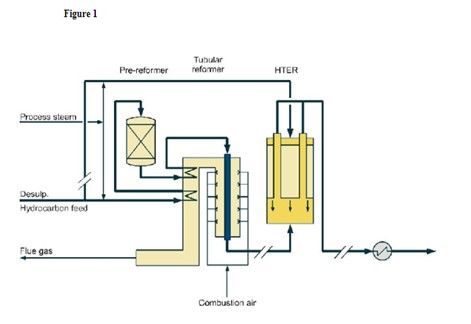
When significant capacity increase (>20%) is desired, this can be achieved by adding a compact convection reformer in parallel with the existing reformer, either a Topsøe HTCR or a HTER convection reformer. HTCR and HTER reformers are very energy efficient and compact reformers that require only a minimum of additional plot area. In order to determine the feasibility of a revamp Topsøe will perform a feasibility study to provide the client with the optimal solution. The study will take into account the status of the existing unit, the various requirements of the client as well as prevailing conditions such as availability and price of feedstock, plot plan, available downtime for revamp etc.
Figure 1 shows a diagram of how an HTER can be incorporated into an existing H2 plant.
Figure 2 is showing a heat exchange reformer being installed in an existing Syngas plant.
Figure 1
Diane Dierking (Johnson Matthey Catalysts)
There are several revamp options available for debottlenecking an existing hydrogen plant to increase hydrogen production. We will address these individually.
One of the simplest ways to increase production is by enhancing the efficiency of the plant. This might include optimizing performance of all reactors in the flow sheet (steam-to-carbon, operating temperature, etc.) over the life of the catalysts, improving combustion in the steam methane reformer (SMR) such as reduced excess oxygen, balanced firing, etc., and minimizing pressure drop by catalyst selection or optimally shaped supports, such as Johnson Matthey’s STREAMLINE™ products. These types of changes can result in incremental gains in production, on the order of 3 to 5%.
Another method of increasing hydrogen production is to re-tube the SMR with tubes having a larger inner diameter. This will be most beneficial to plants that currently have lower alloy tubes installed. By switching to a higher alloy, such as a micro alloy, the tube wall thickness can be reduced. Maintaining the outer diameter of the tubes while increasing the inner diameter achieves an increase in capacity while minimizing any other changes needed to accommodate the new tubes. Note that the spring hangers or other supports will have to be considered, as will any other hydraulic limitations in the flow sheet. This option can provide a larger incremental gain in production, generally 5 to15% with the larger percentage occurring on older plants that have had little or no upgrades in tube metallurgy over the life of the plant.
Installing an additional reactor into the flow sheet can also increase hydrogen production. The most common reactor additions are to add a low temperature shift bed, a pre-reformer or a post-reformer.
For plant configurations that have only a high temperature shift (HTS) bed, a low temperature shift (LTS) bed can be added to provide greater CO conversion in the plant and will likely also provide additional hydrogen recovery in the PSA. The addition of an LTS bed can allow an increase in total hydrogen production of 3 to 5%.
A pre-reformer can be installed downstream of where steam flow is introduced and upstream of the SMR. The benefits of a pre-reformer are additional feedstock flexibility and greater capacity through the steam methane reformer with minimal to no increase in heat duty. Depending on the feed type, modifications to the existing feed pre-heat coil may be required. To get the maximum benefit from a pre-reformer an effluent pre-heat coil will need to be installed in the convection section to heat SMR feed. The amount of production increase is dependent on operating conditions and the available feedstock but can be from 8 to 15% with the greater increase in production coming from heavier feedstocks.
A post-reformer can be installed parallel to the reformer. Some of the combined feed is diverted to the post-reformer, or gas heated reformer (GHR). The reformer process effluent is used to heat the GHR and drive the reaction, which reduces make-up fuel usage and potentially reduces NOx formation. Depending on plant design, this option can increase plant production 10% to 30%.
With respect to refinery off gases, many of Johnson Matthey’s customers feed refinery off-gas streams to the hydrogen plant. Also, many are beginning to evaluate how refinery off gases might be used instead of natural gas to increase the overall hydrogen availability in the plant. Processing refinery off gas in an SMR is most economical for streams that are not hydrogen rich. On an equal molar feed basis, heavier hydrocarbons will provide more moles of hydrogen product than natural gas; this assumes that the off-gas stream is not hydrogen rich. Also, the heat duty to reform C3+ hydrocarbons is less than natural gas, creating the opportunity to reform more of the refinery off gas. If the refinery off gas is too rich in hydrogen, it is possible that hydraulic limitations might become an issue. For refinery off gases which have more than 35 to 45% hydrogen, the economics for recovering that hydrogen with a membrane or PSA become much more favorable. The residual hydrocarbon/off gas from these systems can then become a more easily reformed feedstock for the SMR.
Question 1: What is your experience with emergency isolation equipment (such as a check valve or actuated valve) on the outlet of reactor charge heaters to prevent loss of containment of the reactor loop in a tube rupture scenario? What are the advantages and disadvantages of having this type of equipment?
Michael Chuba (Sunoco)
Sunoco typically looks at the use of isolation equipment on the reactor charge heaters on a case by case basis. The need for these devices is driven by the design configuration of the unit, the process stream being charged to the heater, the emergency depressuring capabilities installed on the unit, and LOPA/HAZOP analysis.
Sunoco’s general heater safety practice is to install a check valve in the combined process outlet of heaters to prevent backflow in the event of tube rupture if there are no downstream vapor depressurizing facilities or liquid blowdown facilities and if the heater operates at 150 psi or higher, and/or if there is a downstream liquid holdup of 350 cu ft or greater. Thus, as previously stated the requirement for a check valve is dependent on the application.
Typically on units where feed to the heater is H2 Treat gas only, these heaters generally have discharge check valves just upstream of where the H2 mixes with the oil as standard practice. On oil only heaters this same practices applies. It is primarily in mixed phase heaters where there is a tendency to find some units with no isolation device and others with discharge check valves. The need for an outlet devise is typically evaluated on a case by case basis. For instance a LOPA analysis on high pressure units with large downstream volume might show the need for additional layers of protection. In this case, a check valve might be added to the design and identified as “safety critical devices”. Being identified as a safety critical device would generally require the valve to be placed on a periodic inspection and test program. Valves of this nature are allowed an IPL credit of “1” during the LOPA analysis. Actuated ESD valves are generally not recommended due to the potential of inadvertent closure and the resulting dead head situation. In most units this would result in the need for additional relief valves for preheat exchanger protection. In addition, if designed with a SIL rating of “1” the ESD receives the same LOPA credit as a discharge check valve.
Vern Mallett (UOP)
UOP’s practice is to install a check valve at the outlet of a recycle gas only heater. UOP does not install a check valve at the outlet of a combined feed heater. The philosophy is that we want to try to keep liquid out of the heater if the recycle compressor stops. Some customers/contractors seem to feel that a check valve at the outlet of the heater will help 3 in some way to prevent a release in the event of a tube rupture at the heater. This ignores the rather large volume of equipment and piping upstream of the heater. In any event the whole unit will eventually depressure through the ruptured heater tube, so the presence of a check valve will not mitigate that. We believe that at least for a combined feed heater, it is better to put the money that would have been spent on a check valve into a more conservative heater design that won’t be as likely to sustain a tube rupture.
If an actuated shutoff valve were placed in this service, it would create a blocked outlet scenario for equipment upstream of the shutoff valve. That scenario might require that upstream equipment be designed for a much higher mechanical design pressure than would be required in the absence of an actuated shutoff valve. UOP does not specify an actuated shutoff valve downstream of a charge heater.
Brian Slemp (CITGO)
The three CITGO refineries have different design heritages therefore different configurations on the furnace outlet backflow prevention. Most of our hydrotreaters do not have backflow prevention on the reactor charge furnace outlets. One of our high pressure hydrotreaters with a recycle gas only furnace has a check valve without an actuated isolation valve. We have never had a tube failure in this system or any other indication that the check valve was ever utilized. The newest hydrotreaters in our system were evaluated for the installation of furnace outlet backflow prevention and the study indicated that check valves were not appropriate. The new unit design incorporated a rapid depressurizing system to minimize the duration and volume of any loss of containment. One of CITGO’s hydrocracking units did have a furnace tube failure and the back flow prevention on the outlet did help mitigate the release inside the firebox.
Question 3: Please discuss your best strategies to prevent overheating of steam reforming furnaces?
Praveen Gunaseelan (Vantage Point Energy Consulting)
The question is general; however, there are a variety of steam reformer designs with different operating and control strategies used industrially so a general answer is provided. Operators are urged to consult with their technology providers or qualified engineering contractors for specific guidance on this issue. For simplicity, it is assumed that natural gas is the hydrocarbon feed being reformed with steam. Steam reforming of methane (natural gas) is an endothermic reaction which requires heat input that is typically provided by the combustion of process off-gas and make-up natural gas. A number of scenarios can result in furnace overheating, including:
•Loss of feed flow (resulting in reduced transfer of heat from the furnace)
•Over-firing
•Hot spots in the reformer tubes (e.g. due to catalyst maldistribution, poisoning, deactivation, etc.)
•Flame impingement on reformer tubes, resulting in stress failures
•Inadequate heat removal during start-up
Accordingly, there are a number of strategies to prevent overheating of SMR furnaces that address potential overheating scenarios, and which need to be used in combination to minimize the possibility of an occurrence. Typical strategies are listed below:
•Increased surveillance, both visual and with devices such as pyrometers, during start-up as well as during normal operation
•Minimize the possibility of hotspots (e.g. closer monitoring of catalyst loading, etc.)
•Reduce the occurrence of poor flame patterns
•Implement advanced control schemes to reduce the possibility of or recover from overheating situations
Brian Moyse (Haldor Topsoe)
First of all regular measurements of reformer tube temperatures and inspection of the radiant side of the reformer is very important.
New hydrogen plants will often be designed with software that allows continuous control of the firing duty with proper adjustments made as function of the hydrogen capacity. All the PSA off-gas is used as primary fuel and the firing control is handled by the secondary fuel.
Obviously a proper catalyst loading with only a minor variation of tube pressure drops is mandatory for proper flow distribution through the tubes. Maldistribution may cause individual tubes to overheat.
Proper catalyst selection and operating conditions should be adopted to avoid carbon formation on the process side, which will lead to hot-banding and tube overheating.
Burner operation should be checked regularly to avoid flame impingement on the tubes.
The Haldor Topsoe reformer furnace is designed to allow for profiling of heat input from burner rows, resulting in catalyst tubes operating at a higher average temperature and heat flux at lower peak tube temperature. This profiling of heat input in itself reduces the risk of overheating of the furnace, but also the measurements of the tube skin temperature made on a regular basis will prevent from operating the reformer with too high tube skin temperatures.
However, the biggest threat to the tubes is a sudden over-heating, which will damage the tubes very rapidly. This could in principal be due to:
•Loss of cooling (feed)
•Too high fuel input (overfiring). Fuel is controlled with a duty controller, summarizing all fuel duty input.
To prevent from such sudden over-heating, the reformer is protected by low feed and steam flow trips, and the fuel is controlled with a duty controller, summarizing all fuel duty input, to prevent overfiring.
Further, as secondary protection, the reformer is protected by flue gas temperature measurement. This is the fastest indicator of over-firing, as process gas in a cold collector can increase in 15-30 seconds if the firing is increased rapidly and a high temperature trip is initiated.
Brian Slemp (CITGO)
The best strategies to prevent overheating steam methane reformer tube:
1)Ensure the catalyst tubes are pressure drop balanced. Reformer furnaces have an inlet manifold to evenly distribute the feed. An increase in pressure drop from an improperly loaded catalyst tube will reduce the flow of the reactants in that tube increasing the tube temperature and potentially leading to coking and overheating.
2)Routinely monitor the skin temperatures and balance the fire box heat distribution to prevent localized hot spots.
3)Prevent direct flame impingement.
4)Routinely monitor catalyst activity with your vendor to prevent operating in the carbon deposition region and generating internal thermal insulation thereby overheating a tube.
5)Maintain proper steam to carbon ratio.
6)Monitor feed composition to ensure potential coke precursors are not introduced above allowable limits.
7)Ensure high purity steam is used to prevent catalyst poisoning and coke generation.
8)Closely monitor tube temperatures and nitrogen flow during startup.
Tina Moss (Johnson Matthey Catalysts)
If not monitored properly, a variety of operating issues can lead to high steam reformer furnace tube wall temperatures. High tube wall temperatures are most often due to poor catalyst loading, problems during start-up operations, or carbon formation due to poisoning. Therefore, the best strategies to prevent overheating of steam reforming furnaces are to address the operating issues that can cause high tube wall temperatures.
The first step in avoiding high tube wall temperatures is to ensure a good catalyst loading that avoids flow imbalances and large catalyst voids. The general tolerance on flow variations between tubes is ± 2.5% for a good catalyst loading, which corresponds to a pressure drop variation of ± 5%. The most common loading technique used by North American refiners is the trickle loading method. There are several trickle loading techniques available in the market and these can typically achieve between 2 to 5% pressure drop variation.
Problems that result in furnace overheating often occur during plant start-ups. Feed flow imbalances on the process side of the reformer tubes often occur during start-ups when rates are significantly less than design. To minimize the impact of the feed flow imbalances, nitrogen flow needs to be sufficient to provide a heat sink as the burners are going through a sequenced start-up. Once steam flow is introduced it provides a significant heat sink but needs to be at least 30% of, and preferably 40 to 50% of the design rate as soon as possible to allow even firing of the furnace. In addition, the operating pressure during start-up should be kept low to maximize process gas velocity and hence improve gas flow distribution as well as minimize the pressure differential across the tube walls reducing the stresses on the steam reformer tubes. While these concerns are most prevalent during start-ups, these conditions can also be present when there are significant rate fluctuations.
Another source of high tube wall temperatures is the result of catalyst deactivation. High tube wall temperatures can occur due to carbon formation caused by insufficient steam rates or poisoning of the catalyst. Insufficient steam to carbon ratios can result if steam flows are not appropriately modified following feedstock changes. Low steam flow can result in carbon deposition on the catalyst and overheating of furnace tubes. Poisoning of the catalyst that results in carbon formation is typically due to sulfur. The best strategy to prevent catalyst deactivation by poisoning is to ensure good purification operation and monitoring during operation. In the event that carbon formation has occurred, one potential strategy is to steam the catalyst to remove the carbon formed. This is most effective if the catalyst loaded in the top is alkali promoted
. Steam reforming furnaces are very expensive, complex units. Overheating of these units can result in reduction in hydrogen production and equipment failure. Creating a strategy to address proper catalyst loading and start-up procedures, as well as, transient conditions during daily operation will help to avoid steam furnace overheating.