Question 1: Historically, instrument air was used to purge FCC reactor instruments. More recently, dry gas or nitrogen is typically used for this service. Please explain the reasons for moving away from air and provide examples of operating upsets that have occurred when using air to purge instruments.
ASDOURIAN (Sunoco Inc.)
Gas purge streams for instrumentation in FCCU reactor-regenerator service are required to ensure their functionality. For example, the reliability of level- and pressure-measuring devices relies on clear impulse lines. The utilization of a continuous-purge gas stream ensures that catalyst particles are prevented from entering or are swept from impulse lines to keep them clear and reliable. Typically, Sunoco FCCUs do not use an air purge stream for instruments in reactor service. We utilize fuel gas or nitrogen for purge in this service. Nitrogen is preferred since it is a dry stream and contains no sulfur. It is also preferred as a continuous emission monitoring and instrument purge for these aforementioned reasons.
Reactor-side instrument air purge has led to elevated phenol content in sour water. Phenol concentrations need to remain within river discharge or biological treatment process limits. We are not aware of any operating upsets of an acute nature when air is in use in reactor service. Instrumentation in regenerator service commonly utilizes air as a purge stream.
WALKER (UOP)
We used instrument air on early units with bubbling bed reactors. With the advent of all riser cracking and tee disengagers in the 1970s, localized coke accumulation became more common. We know of one North American FCC unit that suffered overheating of the reactor head caused by localized coke burn, which was oxidized by instrument air purges. On some units, a shotgun off the top of the tee was used to keep the top head of the reactor active and coke-free. And then as we went to more and more closed systems, dry gas or nitrogen was used as a purge.
WARDINSKY (ConocoPhillips)
We have not experienced any operational upsets due to instrument air purges in FCC reactor service. However, we have experienced problems with riser differential pressure taps using refinery gas purges in one FCC. This was due to heavy coke formation inside the pressure tap piping. An 18-inch coke ball was found on the outlet of one tap. The coking was believed to be partially due to hydrocarbon liquids present in the refinery gas. When switching to natural gas purges in FCC reactor service, proper start-up procedures need to be in place to use nitrogen or instrument air when the reactor is being heated up for a refractory cure and dry-out.
PHILLIP NICCUM (KBR)
Using instrument air to purge FCC reactor instruments has not been a historical practice at KBR. One of the concerns can be that during extremely low feed rates, such as maybe during a start-up or a feed outage, you can have a buildup of oxygen in the top of the fractionator or the overhead drum, which can exceed the explosive limit. All these issues can be avoided by using an oxygen-free medium.
Process
Question 2: Which type of valve technology or design is typically utilized in units with high catalyst withdrawal rates? Do you continuously withdraw catalyst? From a reliability and safety perspective, what type of hardware are you using for control? What is the best withdrawal line design?
THOMPSON (Chevron)
Valve selection for FCC catalyst withdrawal services is dictated by temperature and erosion considerations. FCC catalyst is very erosive and when withdrawn from the regenerator is typically in the 1200°F range. These considerations, coupled with high velocities when purge or carrier air is added, lead to very severe conditions with lots of erosion. We have developed a Best Practice for catalyst handling systems and the information that I will be presenting generally follows those guidelines. We have experience with four types of valves in catalyst withdrawal service. They are a conventional gate valve with or without hard facing; the Tapco Mini Slide; the Everlasting rotating disc valve; and high performance ball valves. Generally, the gate valves have been poor performers, even with hard facing, giving one to three years’ life. Both the Tapco Mini Slide and the Everlasting rotating disc valve have given good performance, typically lasting multiple runs. We have limited experience with the high performance ball valves. Continuous catalyst withdrawal from the regenerator has been suggested as a way to even out the swings in level and catalyst activity that occur when catalyst is withdrawn. We have no experience with that sort of a system, but we have several units that have been interested in perhaps trying it. For units that have power recovery turbines, we do use a form of continuous catalyst withdraw off the third-stage hoppers, which has its own specialized design. For intermittent and semi-batch operation, the valve types described earlier are used for throttling. Block valves are most commonly low chrome gate valves with hard-faced seats. Temperature monitoring of the withdrawal lines is recommended because if the withdrawal rate is very high, then the line may exceed the design temperature. We have a few units that have added fins as a way of cooling the catalyst when it is withdrawn. Carrier air is a big help in cooling the catalyst. Catalyst withdrawal lines are subject to leaks at the erosion points. We have looked at using boronizing and other similar sorts of coatings as a way to mitigate the erosion, but these have not been widely applied. The erosion generally occurs at turns; and so for those, we have used cushioned tees. That is the preferred method for preventing the erosion. Also, we found that air purging of the blocked valves can create localized erosion, particularly if the air is left on when the valve is sitting in a closed position. We had an experience a year or two ago where we actually eroded through the side of a valve body under those circumstances. So the recommendation is to use the air purge strictly when the valve is being moved, either opened or closed, and to leave the air purge off otherwise.
ASDOURIAN (Sunoco Inc.)
Sunoco FCCUs typically use manual gate valves with either stainless steel or chrome bodies on catalyst withdrawal lines. We have air purges on the seat and the stem. Recently, we began installing Nitronic 50 coatings on the stem for added protection against erosion. Along with the gate valves, one of our units uses plug valves; and yet another has a ball valve installed downstream of the gate valve. Several other valve designs have been used to try to improve or speed shutoff and extend valve life. High performance ball valves were installed on one unit for two runs. These valves were much more expensive than gate valves, but the thought was that a quarter-turn design with upgraded seat and design material would give better and quicker shutoff. However, we did not realize a drastic improvement. One unit has tried knife gates, since this type of valve is used extensively on ESPs to the dump catalyst. However, on the hotter surface of the regenerator, the knife gate design did not perform well and experienced many mechanical issues. It has been removed from service. One unit also used the ball valve in one installation; and again, there was no noted improvement in shutoff or service life. One unit uses quarter-turn plug valves; and again, they have seen no major service improvements or drawbacks associated with the plug versus the knife gate. Thus, there have been several attempts to use higher performance valves, but none has worked any better than gate valves. We continue to examine valve options for improved reliability in this service. Regarding continuous withdrawal and control, all of our installations are on units that dump catalysts intermittently. All catalyst dumps are manually controlled based on instrument readings either at the bed level or the online temperature readings, depending on the limitation. The challenge on all these installations is the same: achieving tight shutoff after a dump of very hot and erosive material. The catalyst withdrawal valves are typically reworked and often replaced at each turnaround. Sunoco FCCU catalyst download lines are primarily carbon steel. Some installations use double plates in areas where we expect high erosion, such as elbows. Carbon steel lines have been used with varying degrees of success. Some units have had no issues over extremely long service lives, and others have experienced minor holes that can be managed with patches during a run. On major projects, some alloy has been installed on catalyst unloading lines. Current industry standards regarding design temperatures would dictate using alloy material when replacing unload lines. The use of alloy creates installation and future maintenance challenges. Industry material standards and negative experiences at some facilities would most likely drive Sunoco towards using alloy materials for future catalyst unloading line replacements, even with the challenges of installing and repairing these type of lines.
WALKER (UOP)
UOP recommends continuous catalyst withdrawal for high catalyst users, maybe five or more tons per day. Continuous catalyst withdrawal, in combination with continuous makeup, allows you to minimize the catalyst level and inventory. This results in better activity maintenance and lower particulate emissions, as well as reducing manpower requirements. We recommend Everlasting rotating disc valves to control the flow of the catalyst. Cooling fins are used on the withdrawal line to cool the catalyst before entering the hopper. The alloy metallurgy is used to accommodate the high temperatures associated with the catalyst withdrawal. Carrying air is used to cool the catalyst and maintain the line below allowable temperature limits. Flow controllers are used to adjust the carrying air and skin TIs are used to monitor the temperature. Everything is controlled by the DCS and runs with very little operator intervention. The system is essentially a regenerator-level controller with a very slow reset. The withdrawal valves are normally closed, then opened periodically for a short time, and then closed again. We do keep a gate valve adjacent the regenerator for isolation.
WARDINSKY (ConocoPhillips)
We typically rely on a series of two to three gate valves to withdraw catalysts from the regenerator. Some of these valves have actuators on them. The valve internals are metallurgically enhanced to reduce erosion; and for high temperature service, we plan on replacing the valves at each turnaround. With the exception of third-stage separator underflow, we do not continuously withdraw catalysts from our regenerators.
HAZLE (NPRA)
I want to remind you that your Answer Book includes some of the panelists’ responses as well as responses from other people that submitted them before the conference. I encourage you to open that and follow along and keep track.
KEVIN PROOPS (Solomon Associates)
Aram, when you were talking about valves, you mentioned that you have or have considered stainless steel. You also mentioned that you are considering alloying the line. I believe, Pat, you used the word alloy. I believe we have brought up, in the past at these sessions, concern about polythionic stress corrosion cracking in this service, and I would like to confirm or clarify whether we are talking about the 300 series stainless or something else. My experience would be that if you are having problems with erosion on the line and you are considering alloy, then I think, economically, you might do better to have a larger pipe or go with the cushioned tee-type installation and not go to alloy because I have experience with these lines lasting a very long time in carbon steel service or low chrome. I would like to hear comments on metallurgy from both Aram and Pat.
ASDOURIAN (Sunoco Inc.)
You bring up a very good question. We do have folks that we pay to take care of this type of alloying questions. Unfortunately, I am not one of them, but I can query those personnel and put my response in the Answer Book.
WALKER (UOP)
I agree with the polythionic stress corrosion cracking comment. When I refer to alloy, I mean 5-chrome or similar.
THOMPSON (Chevron)
I would agree with that. We typically have 5-chrome. We have a few places that have selectively used just 1¼-chrome, but usually it is 5-chrome. We stay away from 300 series stainless for the reason you mentioned: that PSCC is a known risk and there is really no need for it at that location.
PHILLIP NICCUM (KBR)
I would like to just agree and reinforce that in catalyst withdrawal service, we would definitely recommend staying away from a stainless steel, such as 304-type stainless steel. We have seen instances where it had been used and the lines would break due to polythionic acid cracking.
MASHUD MARTLE (KBR)
In the past, we have used stainless steel 321-X for catalyst withdrawal lines and kept avoiding the polythionic corrosion. We kept nitrogen purge so that keeps a continuous flow into the regenerator to the flue gas, which does not condense, and it keeps the nitrogen as a blanketing. We used 321 stainless steel and it worked very well in a few instances.
ZIAD JAWAD (Shaw Stone & Webster)
Mike, you mentioned the flue gas fines collection systems. In those systems with the fourth-stage underflow, do you utilize gravity drain down into the fine topper? Has anyone seen corrosion in the fine topper if it is pressured up in that service?
WARDINSKY (ConocoPhillips)
I am not aware of any corrosion problems in those lines. I have not heard any reports of that. We do have, I believe, some fourth-stage separators with gravity drainage to a hopper where the catalyst is then cooled and offloaded later.
WALKER (UOP)
I have heard of corrosion in that area. The catalyst accumulates down there. It can insulate and you can trap corrosive materials. We insulate and heat-trace that area.
ZIAD JAWAD (Shaw Stone & Webster)
In those services, do you have metering block valves or different types of block valves? Do you have corrosion in those lines as they meter the catalyst down to the fine hopper?
WALKER (UOP)
Those hoppers are usually on a timer and they are periodically unloaded to maintain the level. I am not sure if that answers your question.
WARDINSKY (ConocoPhillips)
Yes. The hoppers are typically unloaded at least once a shift in that service. I am not aware of any corrosion issues associated with the valves.
REZA SADEGHBEIGI (RMS Engineering)
Besides temperature that Ralph mentioned, one of the key criteria in designing those valves is the pressure drop. You know, the regenerator pressure can run anywhere from 15 pounds to as high as 50 pounds. So when you look at designing that valve, you are taking a lot of pressure drop if you are running a 40-pound regenerator and you want to go down to zero, basically, or one- or two-pound. So that is the one you have to look at. It is similar to designing a slide valve. You may need to have a two- or even a three-valve system to allow you to take reasonable pressure drop across the valve. Otherwise, it is not going to last very long, especially if you have to withdraw very often. The other thing that I have seen happen is that erosion in the piping that you were talking about downstream: Most cat crackers do not pay attention to how much purge air rate they have going through there. They just open the valve. They have no idea whether it is too much or too little. I would recommend putting some sort of a restriction orifice or a flow meter and target about 30 fps velocity. That will ensure that your catalyst is moving and that you do not have erosion, especially around the elbows. Thanks.
DOC KIRCHGESSNER (W.R. Grace Refining Technologies)
Pat, I would like to ask you, in particular, a question. You commented about the simple regenerator-level control scheme. Would you care to comment how prevalent this is in actual practice? About how many people do you know who are actually, continuously, adding and withdrawing catalysts from the FCC regenerator?
WALKER (UOP)
I am not sure how many continuous withdraw systems we have operating. I am intimately familiar with one that is working very well in the Middle East, and I believe we have a handful of other ones that are also working without any problems; again, using the Everlasting valves. Prior to that and since the beginning of cat cracking, it was done periodically maybe once a day or once every three days, depending on the unit, and that still works fine. It is still the most common industry practice.
WARDINSKY (ConocoPhillips)
I am a little skeptical of the continuous withdraw system because within our system, we see a lot of units struggle to maintain a continuous addition to minimize swings in the unit operations. One of the first things we do when we go out is to try to get people to look at loading systems that are reliable and that maintain a continuous addition to the regenerator. We still seem to experience a lot of problems with loading systems and reliability of those systems.
WALKER (UOP)
I have just one more comment on what Mike said about addition systems. It seems that the most reliable, repeatable systems are those based on day hoppers on weigh scales.
Submitter
Process
Question 3: Carbonate stress corrosion cracking (CSCC) has been identified as a cause of failure in FCC main fractionator overhead systems. What changes in feed quality, unit operation, or configuration would lead to increased risk of CSCC? What parameters do you monitor to determine whether a system is susceptible to CSCC? Has the problem been significant enough to warrant either comprehensive PWHT in potentially affected areas or localized PWHT when problem areas are identified?
THOMPSON (Chevron)
Carbonate stress corrosion cracking, CSCC, is characterized by inter-granular, sometimes branchy, scale-filled cracks. It is believed that ammonium carbonate is the main contributor to the cracking mechanism. Scale is typically black magnetite, and the corrosion, as far as the corrosion product, and sometimes iron carbonate, which is unlike the sulfide stress corrosion cracking that occurs with iron sulfide.
Chevron finds that the work by Kmetz and Truax published in 1989 still holds true. The conditions under which CSCC are a threat include susceptible material, which would be carbon steel that is either not post-weld heat-treated or poorly post-weld heat-treated; pH levels above 9.0 and carbonate concentrations above 100 ppm; or pH levels between 8.0 and 9.0 and carbonate concentrations above 400 ppm; and finally, electrochemical potentials between -500 and -600.
Stainless steels are basically immune to carbonate stress corrosion cracking and some facilities have used that as a way to solve the CSCC problem. We basically monitor the parameters of pH and carbonate levels to determine if we are in the range where CSCC is a problem, especially if we have non-post-weld heat-treated equipment. It is easier to monitor pH than anything else. And if we have a good sense of the carbonate ranges, pH may be the only parameter that we monitor.
Higher nitrogen levels will lead to higher ammonia. And of course, this result will increase the pH, which could lead to CSCC. Similarly, anything that promotes CO2 will increase the amount of CO2 that is available. We found in the 80s, when we went to complete combustion on many units, that series of events really tipped us into the range where CSCC was a problem.
We know that there are a number of companies that look at the sulfur/nitrogen ratio and we find that this ratio can be useful. Nevertheless, we use pH measurement and carbonate measurements as the defining parameters for monitoring.
Regarding the use of post-weld heat-treat as a mitigation against carbonated stress corrosion cracking, we are convinced that it is very effective if the heat-treatment is done properly and there are no unusually applied external stresses. We found that we needed to go to a more severe post-weld heat-treat than is typical—for example, what the code would require— and we have to have better temperature measurement, wider bands, and things like that.
Our standard practice is to call for post-weld heat-treat for all new systems that are subject to CSCC and also on systems where we might be changing conditions where that could be a factor. Since implementing these procedures, we have not had an incident in over 10 years now.
WALKER (UOP)
The question mentions that CSCC was found in the main fractionator overhead system, but I would like to point out that carbonate stress corrosion cracking has also been reported in the gas concentration unit although only in locations where there can be an aqueous phase. So you would not expect to see this in, say, the debutanizer, but you might see it in something like a high-pressure condenser.
The problem is most pronounced in hydrotreated feed derived from high nitrogen crudes, such as Californian or Nigerian. Hydrotreating is very effective at reducing sulfur but less effective at reducing nitrogen. So if you start with a high nitrogen gas oil and severely hydrotreat, you can wind up with an FCC feed that has a very high nitrogen-to-sulfur ratio and subsequent high pH.
Most of the equipment in the main column and gas con is already heat-treated because it operates in wet H2S service. Consequently, the carbonate stress corrosion cracking is generally limited to the piping, which is normally not heat-treated, even in wet H2S service. I would like to also point out that this problem is fairly uncommon. Since first reported, we have only had one of our grassroots units deemed at risk for this, which justified unilateral post-weld heat treatment.
ASDOURIAN (Sunoco Inc.)
Sunoco FCCUs typically do not process hydrotreated feed; therefore, the naturally occurring sulfur-to-nitrogen ratio, which has been linked to this phenomenon, is not being altered. We have not observed CSCC at any of our FCCUs. Our FCCU overhead systems have had enhanced inspection programs in place for corrosion and cracking for quite some time.
These inspection methodologies include wet fluorescent magnetic particle inspection for environmental cracking. Our associated sour water strippers are post-weld heat-treated to mitigate potential metallurgical impact of carbonates since this can manifest itself in those systems. The primary control that is used is post-weld heat-treatment of the welds. The post-weld heat-treatment, we have found, has also improved the resistance of welds to wet H2S and cyanides attack, which is common in these types of systems.
WARDINSKY (ConocoPhillips)
ConocoPhillips has experienced carbonate stress corrosion cracking in one FCC main fractionator overhead and wet gas compressor system in which intergranular and base metal cracks were discovered in 78 welds. This unit runs 100% hydrotreated feed with a high nitrogen content. Eighteen full-separation clamps were installed until the affected piping could be replaced at the next turnaround.
SHELLY ROMMELMANN (Washington Group International)
Aside from clamping, if you have a couple of years until the turnaround and you are operating in a carbonate stress corrosion cracking range, what can you do operationally to alter the pH without using mass quantities of water for dilution or harsh chemical addition?
WARDINSKY (ConocoPhillips)
I think the unit in question that experiences this within our system probably looked at various chemical additives, such as ammonium polysulfide (APS) and filmers that would protect the surface of the metal. Obviously, they implemented more elaborate lab testing and started looking at pH and monitoring carbonate levels in the sour water.
THOMPSON (Chevron)
I would say that without implementing some proactive responses, such as selective heat treating and things like that, it is going to be difficult to address CSCC without some sort of a turnaround. Usually, you are in a position where oftentimes you cannot change the chemistry enough to be able to get yourself out of the range. That is very unit-specific; however as Mike mentioned, there may be the opportunity to, for example, switch from APS to a filmer as a way to control corrosion if you are just marginal.
For example, one of the things we found a little bit disturbing is that we even had cracking at places where pipes were supported in pipeways. This was completely outside of weld zones. So sometimes this occurs in locations where you would not even expect it, making it very difficult to do enough monitoring and really pick up all the locations where you might be at risk.
SAM LORDO (Nalco Energy Services)
I do not have anything to add to the panel’s response, but there is a NACE Task Group that is looking at this issue. It is TG347 and they will be issuing a report. They have actually done a survey of the industry. As you have heard, there are a lot of things that go into this carbonate cracking that are not well understood and rules of thumb do not always apply across the board. So what they have done is they have surveyed the industry and tried to capture all the incidences out there that have occurred and what are the parameters around them. Also, I would like to note that in several locations, we have been successful when applying a filmer in places where carbonate cracking has been known to occur.
REZA SADEGHBEIGI (RMS Engineering)
You can reduce the amount of the ammonia produced in overhead by cutting back the riser temperature or basically slowing down the severity of the cracking. That can be done by reducing riser outlet temperature and maybe by putting in more active catalyst. That way, you slow down the cat circulation, yet do not lose that much on conversion. Also, that person who asked that question needs to look at the air distributor, as well as the catalyst withdrawal system regen catalyst. If you are dragging all of the CO2 down with the flue glass into the reactor, then you must have a mild distribution problem. Normally, you have the flue gas coming down and there is a ratio of the nitrogen to CO2. If that CO2 is higher than it is supposed to be, then you can look it up at the sponge absorber off gas. Normally, a sponge absorber off gas has somewhere between 1% and 2.5% CO2 in it. If you see that number has gone up, then you have to look at your regenerator to see how air and a regenerator catalyst withdraw nozzle are working out. So by reducing cat circulation rate and reducing riser temperature, you reduce the ammonia. And at the same time, you reduce the amount of entrained CO2 that goes down into the reactor.
WARDINSKY (ConocoPhillips)
I want to mention that I believe the corrosion community is divided on whether APS has any mitigating effect on the carbonate stress corrosion cracking. About half of them believe it works and the other half do not. That is maybe one of those things that will come out of the NACE Task Force.
I was thinking more about this question. I believe that the unit where we experienced it did try to raise their water wash rates to try to reduce the pH. This is a unit that if you cut back riser outlet, you are going to make more slurry; and so, you are going to hit some constraints somewhere else. That is probably easier said than done. They basically just held on for two years until their next scheduled turnaround.
Submitter
Process


Question 4: Does your refinery/company adopt a time-based rather than inspection-based replacement strategy for FCC reactor and regenerator hardware such as feed nozzles, air distributor, cyclones, cyclone support systems, and flue gas expansion joint bellows? If so, what is the planned service life for this equipment?
THOMPSON (Chevron)
It depends. I had to throw that in there. FCC folks always say that. Service life of each component is highly dependent on the application and varies from unit to unit. We have generally found that inspection-based replacement frequency is used as opposed to time-based. We use the results of the last unit inspection, coupled with a run history, to determine whether we need to replace a particular component.
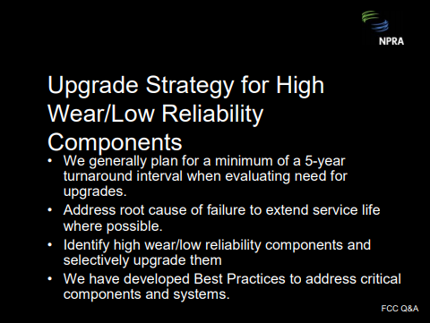
Unit monitoring is extremely important and we do not want any surprises when we open up the unit. As an example, we would try to use cyclone erosion predictions to determine whether we are going to have an issue with cyclone wear when they get inside. We have adopted an upgrade strategy for high-wear, low-reliability components. We generally plan for at least a five-year run. And if we have components that will not make that run, then we try to address those selectively. We have developed Best Practices for most of those components.
Our expectations for typical service life of some of these components would be feed nozzles—five to 10 years; air distributor—15 to 20 years; reactor and regenerator cyclones—15 to 20 years; cyclone support systems—15 to 20 years; and, flue gas expansion bellows—15 to 20 years. Again, this service life is highly dependent on the severity of the unit and the particular configuration.
Obviously, operating conditions and run history have a big effect on the service life. The other thing that we found that is a big impact is the number of shutdowns. If you have a lot of emergency shutdowns or the unit is unstable a lot of the time, that is going to greatly affect the service life.
WARDINSKY (ConocoPhillips)
We use a combination of inspection-based and time-based replacement schedules for converter section internals; for example, feed nozzles, depending on the particular licenser nozzles used. It is not uncommon to replace feed nozzle tips on each turnaround. We generally recommend that everyone have a spare set of nozzle tips or nozzles around ready for replacement on turnaround.
We would typically start looking at replacing regenerator internals, such as cyclone systems and air distributors, after 15 to 20 years of service or if significant sigma phase embrittlement is evident from metallurgical analysis. Reactor disengager and cyclone systems can last longer—25 years or so is not uncommon—before metallurgical changes, such as carbide formation, start to limit welding repairs. This assumes that these equipment items are not replaced sooner during capacity expansions. Flue gas expansion joint bellows replacement is completely based on inspection criteria, except for bellows upstream of flue gas expanders, which typically are replaced every turnaround.
ASDOURIAN (Sunoco Inc.)
Sunoco relies on an inspection-based replacement strategy. The inspection-based strategy for the listed items will vary by component. Many factors come into play when making these determinations. Note that the inspection for all but one of the components—that being the flue gas expansion joint bellows—must be done when the unit is down. And even on the bellows, a complete visual inspection cannot be performed on the expansion unit when the unit is running. Therefore, these two must be looked at when the unit is down.
The inspections are performed using guidance and knowledge provided by these documents: API-RP571—Damage Mechanisms Affecting Fixed Equipment, API-RP579— Fitness for Service, and API-RP936—Inspection and Testing Monolithic Refractory Linings and Materials. These are the documents our Inspection and Reliability folks utilize.
The listed components, and others, are subjected to a document review as early as 24 months prior to the turnaround. The historical inspection records are reviewed by the team and a determination is made of the likely condition of the components. These are reviewed by the business team during the Turnaround Preparation meetings. An inspection work scope is then generated and assigned to each of the components. Upon gaining access to the equipment, a condition assessment occurs utilizing all of the documents. The conditions are noted in the inspection report and items that revealed excess wear and damage will be noted in recommendations for future repair or replacement.
JIM WEITH (Mustang Engineering)
One thing I did not hear addressed was the flue gas piping, as I said I worked on some time ago. We learned from the metallurgical folks—who can explain this better—that apparently things migrate in stainless piping. This was a hot-wall pipe. After 12 to 14 years, it starts cracking. We did have that experience. Every time we had a thermal cycle, we would come up and find a crack in our flue gas piping. Then, we would have to schedule in time to get that fixed. And of course, it was always at some out-of-the-way place that was nearly impossible to get to. So ultimately, we bit the bullet and replaced the flue gas piping in its entirety.
WALKER (UOP)
I agree with that. What we do is with the entire flue gas is cold-wall for a new unit. That includes the line, the orifice chamber, and the slide valve.
WARDINSKY (ConocoPhillips)
The only place nowadays where you expect to see a hot-wall system would be upstream of the expander and those areas do require special attention from the mechanical folks to make sure the metallurgy that exists there is still in good shape.
Submitter
Question 5: What is the shortest possible time between oil out and entry for maintenance on large inventory, high capacity FCC units? How is this achieved?
HOWELL (Holly Refining)
With FCCs at 27,000 bpd and 9,000 bpd capacity, neither of our units really qualifies for high throughput or large capacity. However, in discussions amongst the members of the panel, we found that throughput and inventory are not necessarily good indicators of how quickly you can move oil-out to maintenance-in.
Historically, Holly has obtained our first entry permits for vessels in the FCC complex 36 to 48 hours from oil-out. During a recent unplanned outage in one of our units, we were still able to open the external manways within 48 hours of oil-out. We were able to do a visual inspection, which was our first-entry in the complex, about 24 hours later at 72 hours from oil-out. We were unable to enter the reactor for three more days, however, mostly due to coke buildup in the reactor vessel. In fact, we were not able to steam because of the circumstances of the shutdown.
With our infrequent FCC shutdowns, we found that the best method for getting into the vessels rapidly is using a set of Evergreen procedures. The latest version of those procedures is stored electronically on the company Internet. Several days prior to any shutdown, operators conduct a Safety Task Review with the engineers, Operations management, and shift supervisors. The procedure is read through with a critical eye. We make any changes necessary at that time. As the unit is shut down, procedures are checked off and annotated so that after the shutdown, we can go back and incorporate those into the most current, correct version of those procedures.
WARDINSKY (ConocoPhillips)
ConocoPhillips operates four FCCs with more than 450 tons inventory. The largest in our system is 650 tons. Three of these run more than 80,000 bpd throughput. The shortest period between oil-out and regenerator maintenance that we have been able to achieve is 48 hours. Getting into position to isolate the converter section from the main fractionator is a first key step. There are several steps that can facilitate the shutdown time elements, as shown on the list. First, you want to make sure you have a lock-out/tag out location list and plot limit blind list well in advance of the shutdown. Assign teams to go out and get those blinds in and positions tagged out. Reduce feed rates to a minimum. Reduce catalyst inventory to a minimum. Circulate catalysts just long enough to burn off the coke and cool it down. Again, one of the main factors in gaining access is getting catalyst out. Keep the regenerator pressure high enough to facilitate catalyst withdrawal. You might want to look at supplemental compressors for that. And then, get your boiler makers working on the manways, hot bolting them as you are blinding.
THOMPSON (Chevron)
FCC shutdown timing is set by requirements to isolate the equipment and remove the catalyst and oil. We have considered three days as pacesetter. Unfortunately, our larger units tend to be a little longer than that. We find that the roadblocks to rapid entry are typically catalyst withdrawal and isolation. That includes reaction mix blind installation.
To speed the catalyst withdrawal, we have gone to either multiple withdrawal points or we use of external catalyst coolers to basically allow us to withdraw catalysts at accelerated rates. As far as getting the reaction mix blind in, we have a couple of units that have the Zimmermann and Jansen mix valves that allow us to isolate the fractionator from the reactor. However, you still have to put a blind in because those systems will not allow you to get entry with just the closed valves.
ASDOURIAN (Sunoco Inc.)
Sunoco successfully opened the doors for entry into the reactor regenerator on one occasion within 30 hours of pulling feed on an FCCU. This particular unit has a 750-ton inventory and runs in excess of 80,000 bpd. However again, this was just one occasion. Typical for us is 48 to 60 hours. The timing associating with catalyst de-inventorying is probably the single greatest contributor to being able to expeditiously gain access. Other factors contributing to expediting the process are dumping catalyst via multiple nozzles and the experience level of the Operations staff that are on duty at the time when this is occurring.
KEVIN PROOPS (Solomon Associates)
We do not have data on the oil-out/oil-in or oil-out to mechanical entry, but we do have data available for what is Best Practice on FCC turnaround duration overall. This data is from 278 FCC turnarounds between 2000 and 2006. Out of those 278, we have seen 10 or 12 units of all scale—from less than 25,000 bpd to well over 100,000 bpd —that define Best Practice. This is a line that is defined as three times the unit capacity of 1,000 bpd plus 290, which gives you hours of downtime; so again, three times capacity plus 290. What that equates to is for a 50,000 bpd unit, you are looking at about 18 days of downtime. For a 100,000 bpd unit, it is about 25 days of downtime. So clearly, we do see scale effects on this. Since we have many clients that have small refineries and small units that worry that they cannot achieve the same performance as big refiners do, I would like to reinforce that there are some things smaller refineries and smaller units do seem to do better. One of them is shorter FCC turnarounds.
MATT BAILEY (Valero Energy)
I have a question on resid crackers. Are people seeing more issues with high CO levels in the reactors upon initial manway openings and what are people doing if this is encountered?
WALKER (UOP)
CO is a combustion flue gas. That should all be gone early in the shutdown. Am I missing something here?
MATT BAILEY (Valero Energy)
Yes. We have had this experience and I have talked about it with some other folks in the industry. On initial breaks on the reactor, you go to sniff that reactor at that manway. And despite having a good ventilation on the reactor, if there is a lot of coke inside the reactor due to either a breach in the riser termination device or some other mechanical failure that is occurred, there is a lot of coke contained inside that reactor, There is actually some smoldering that goes on inside that reactor as a result of maybe not cooling down the reactor during the decommissioning step. I am just wondering if anyone else has had that experience.
WALKER (UOP)
I understand the question now. We are talking about on the reactor side. Yes, I have heard of this scenario and yes, you do have to be very careful, particularly with resid units or other units that have a history of building up coke in the reactor. You do need to be cognizant of this when you first break open the manways. You also need to be ready to snuff that out with steam or close the manways back up again until you can get further cooling.
THOMPSON (Chevron)
I want to add that it can also be a problem on the regenerator side if you shut down in an emergency basis and have unregenerated catalyst in the regenerator. You can generate a high CO environment. And when you open the manway, if the catalyst is hot, you could get a detonation. That is something to check very carefully before you fully open things and enter.
JIM WEITH (Mustang Engineering)
I have two comments. Many, many years ago, we had a 5,000 bpd FCC with maybe 40- ton inventory. We have a novel feed nozzle arrangement—Ventory-type—that our licensor had provided for us and it plugged off about every six weeks. So for about the first six months until we replaced those, we were shutting down every six weeks to pull those nozzles out and clean them. We got pretty adept at that although we did not have to enter the reactor. All we had to do was de-inventory the regenerator. So it was: shutdown, cool down, de-inventory, pull the nozzles, clean them, put them back in, re-inventory, and up again. Feed-out to feed-in was typically 36 hours, as I recall. We got pretty adept at it after the third or fourth time. That was a genesis of an article written in the Oil & Gas Journal some time ago about using diagrams for unit startups, which can be applied to shutdowns as well.
The second example occurred at a Los Angeles refinery. You might anticipate that people were reluctant to have any emissions so they felt they always had to shut the air blower down before the catalyst extend pipes lost their seals. This resulted in a lot of catalyst being left behind in the regenerator. Then, you had to open up and vacuum out, which took a couple days because it was hot. Generally, we had one or two personnel burn incidences each time that happened. This could have easily been rectified by at least putting trickle valves or some sort of a heel device on the secondary cyclones, if not both sets of cyclones so they could run the air blower longer.
PHILLIP NICCUM (KBR)
This is a question for Ralph Thompson or anyone else who would care to answer. For units that have a valve between the reactor and the main fractionator, have there been issues with an inability to close that valve after it has been in service for a while, perhaps, due to coking somewhere in the system?
THOMPSON (Chevron)
I am not aware of the valve coking up to the point where it could not be closed. However, I think that is a potential concern because if you have a long run, you have a lot of coking. And of course, there is a point where you could have heat loss. At least, there is a potential for some coking there. I must admit that we do not have enough run experience on those systems to be able to answer that question one way or another. Certainly, I mentioned that you really do need to be able to install a blind, in addition to the valve, so that is another consideration in that installation.
WARDINSKY (ConocoPhillips)
Phil, I assume you are talking about the multiple-use, isolation blind device valve? Then yes, we have several of those in our system. Thus far, I think we are about two or three years into a run using one of them on one unit and it has worked fine. It has not failed.
WALKER (UOP)
The traditional gate valve-type: You could ask the audience here, but I know a number of people who have had trouble shutting those at the end of the run due to coke formation. You clear the coke out and you can use it during the startup, but problems closing them are not uncommon.
ASHOK MATHUR (KBR Solutions)
I just want to warn against storing procedures only on the Internet. I have two procedure manuals myself. We had a shutdown during complete power failure. Not even the PC was working so I was very happy that one guy had a hard copy in a drawer. Also, your IP friends can let you down when your server is down. And when you are starting up, you have no access to anything. So I really would like to make a plea: Keep a hard copy of your procedures somewhere in a drawer, even if your Quality people do not like it.
BOB LUDOLPH (Sunoco Inc.)
I would like to address Phil Niccum’s question regarding the history of closing these valves and whether it has been a problem. We have one location that had a Zimmermann and Jansen installation. I am aware of one occasion where we had difficulty closing that. We eventually did. I cannot stress enough the maintenance of these valves. When you come down for a turnaround, pack and seal them properly. Go through all the proper procedures and they will be reliable for you. Also, the hydraulic gun that is used for sealing it is a very valuable piece of equipment. There is not really a substitute that you could find in a refinery for one of these devices, so protect it that it does not get misplaced.
SHELLY ROMMELMAN (Washington Group International)
To piggyback off the gentleman’s question regarding coke formation in the dilute phase of the reactor: Say your refiner has a few close-couple cyclones and they choose to reduce our water-make by turning off their dome steam. Do you guys have any recommendations to minimize coke formation for startup or shutdown?
WARDINSKY (ConocoPhillips)
If you are not using dome steam on a close-coupled cyclone system, you are probably going to be looking at a lot of coke in the reactor. So the first thing I would say from a maintenance standpoint is prepare to get in there with a crew of people with jackhammers to go at it. It is probably going to add some turnaround time. We have had some failures of closecoupled systems in the crossover ducts where we have not seen any indication of that, in terms of a yield shift. But when you went in on turnaround, there was coke the size of a Volkswagen up in the reactor. I think that is how they phrased it. They got to the point where they were looking at having to dynamite it out. I do not think we got that far along. I think we started using some jackhammers and got it out. It will delay your turnaround time because if you are doing any work lower down in the reactor or the stripper vessel, it is going to have to wait until you get all that coke out of there.
WARREN LETZCH (Shaw, Stone & Webster)
I would have to say the same thing. I think you would be much more advised to try to reduce the stripping steam or something else if you felt you had a sour water problem and address that issue. I would not have thought that the amount of dome steam you were putting in was all that significant compared to, say, the dispersion and stripping stream that you put through the unit. In my opinion, the coking issue in the top of a reactor like that is such a safety issue that I do not really understand why anyone would even consider doing that, based on the talk we had this morning.
WALKER (UOP)
You could probably get away with less dome steam if you had very clean feed than if you had heavier feed there. My observation is that there is a pretty strong correlation there.
Submitter
Process