Question 34: When processing cracked naphtha, what is done to ensure that polymerization of the diolefins/olefins will not result in pressure drop problems in a reactor or upstream equipment?
GATES (Motiva Enterprises LLC)
Again, we are trying to prevent the polymerization of the olefin/diolefin. The primary concern is trying to prevent contact with oxygen because that will ultimately lead to gum formation. So the preference would be, if possible, to feed this hot to all the downstream units and avoid intermediate storage. If you will have to put it into tankage, the preference would be to use an internal floating roof tank and add some type of chemical stabilization. So typically, some kind of oxygen scavenger would be put in there. The length of time that material will be staying in tankage may dictate the level of treatment that will be done.
The other concern is that if this material contains diolefin/olefins, as it goes into your feed/effluent exchangers, prior to entering the reactors, it could potentially foul those exchangers. Often, you want to add soak hydrogen or hydrogen upstream of that exchanger. It may need to be considerably upstream to ensure that as the material is going into the exchanger and getting hot, there will be some hydrogen present to prevent that gum formation.
If you are actually going to try and treat cracked naphtha, you will typically want a separate diolefin reactor that will be run at lower temperatures to avoid the polymerization. You will use catalytic hydrogen to eliminate the diolefin and operate it in a regime such that you will not saturate too many of the olefins. You are ultimately trying to put the naphtha into gasoline, so you want to minimize your octane loss for the gasoline pool. As far as the catalyst, look for a catalyst with sufficient surface area and large enough pore volume – going back to Sal’s comment – to manage any silicon or arsenic that might be coming with that cracked naphtha.
WATKINS [Advanced Refining Technologies (ART)]
Two of the reasons we are worried about olefins and cracked naphtha in our naphtha hydrotreater are that they are a large consumer of hydrogen and also because the reactions occur quickly. Once the reaction with olefins starts and we have enough temperature, it is hard to stop. We do not want excess temperature to coke up at the top of our hydrotreater. Like David said, with coker feeds, we would like to see them brought in straight from the coker while still hot. They should not be sent to tankage; and if they are, you should blanket the tank somehow and keep it protected from oxygen.
The top of the hydrotreater is where we are worried about excess exotherm. We want to spread out that heat and do the reaction somewhat slowly, if possible. We do not want to have it occur all at once. Generally, we will recommend a graded bed to mitigate that pressure drop and start olefin saturation to avoid worrying about anything else like HDS and HDN or aromatics. In that case, we will be using a low-metals guard material at the top of our hydrotreaters, which also gives us the ability to pick up silicon.
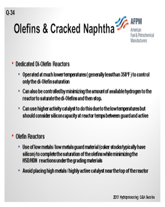
If your system has a high amount of diolefins, again, a dedicated diolefin reactor is important. At a much lower temperature, you can actually control just the diolefin reaction and avoid doing everything all at once by either controlling how much hydrogen goes to the hydrotreater or by keeping the temperature fairly low.
In the top of the main reactor of a coker naphtha unit, again, low metals, a guard material, is recommended. We generally then recommend avoiding the placement of very high-metals, high-active catalysts at the top, if at all possible, so we can try and do the reactions one at the time.
MUKESH PATEL (Reliance Industries Ltd.)
When we have to enable storage of naphtha, if necessary, which is the parameter we should monitor or what type of analysis should be carried out to determine if any gum formation has happened?
GATES (Motiva Enterprises LLC)
Off the top of my head, I do not know the ASTM (American Society for Testing and Materials) methods for that, but there are gums and then there are potential gums a
We run diolefin saturation tests, and I will put the ASTM method in my Answer Book response. We typically shoot for 60 to 80% diolefin saturation.
SHARPE (Flint Hills Resources, LP)
We run diolefin saturation tests, and I will put the ASTM method in my Answer Book response. We typically shoot for 60 to 80% diolefin saturation.
BRIAN WATKINS [Advanced Refining Technologies (ART)]
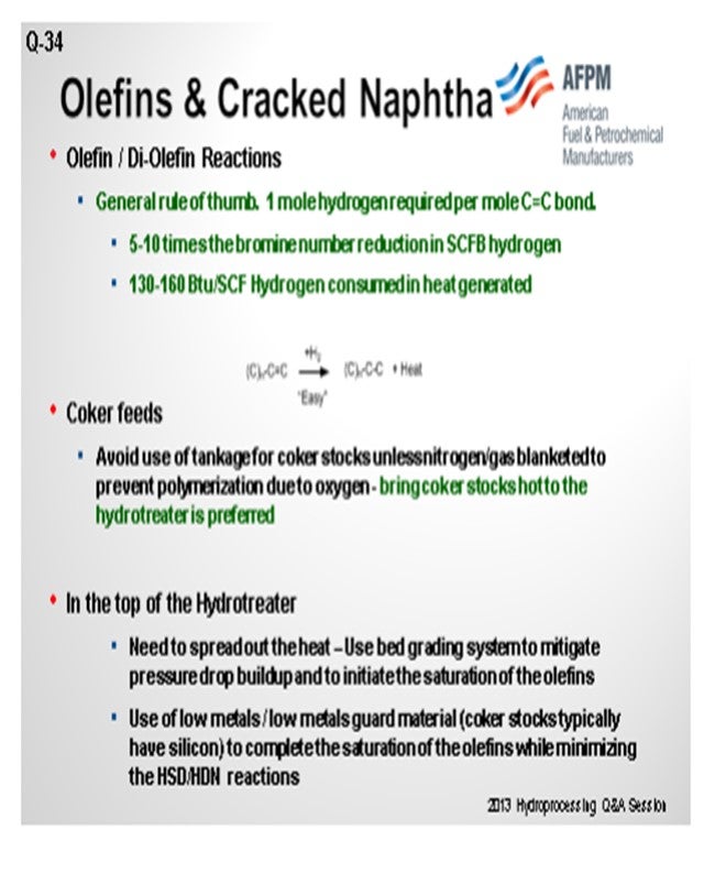
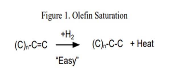
Processing coker naphtha can have several undesirable effects on the performance of the hydrotreater and the catalyst if the system was not properly designed to handle it. In general, coker stocks have a higher level of olefins present from the coking process. Once in the hydrotreater, these olefins will quickly get saturated (Figure 1), resulting in high hydrogen consumption and generation of a lot of heat. As a general rule of thumb, one mole of hydrogen is required per mole of carbon-carbon double bonds, or between five and 10 times the Bromine number reduction in standard cubic feet per barrel (scfb) of hydrogen. This additional heat [130 Btu/scf (British thermal unit per standard cubic foot) to 160 Btu/scf hydrogen consumed], if not managed properly, will initiate additional reactions, quickly creating a very high temperature rise. The high temperatures can accelerate coking and can lead to olefin polymerization, resulting in a dramatic increase in pressure drop. This can set an upper limit on how much coker naphtha can be processed based on the need to limit the heat rise or hydrogen consumption.
A system that is properly size and activity graded is extremely important when processing coker naphtha. ART recommends utilizing a grading system to help mitigate pressure drop buildup. A large inert hold down ring (GSK-19) with a very high void fraction used for trapping large particulates is placed at the top of the catalyst bed. A smaller diameter macroporous ring (GSK-9) that traps iron, as well as other fine particulates, is typically used in the next layer. After that, two types of smaller rings are used as active grading. These materials have a low level of active metals which help begin olefin saturation reactions, as well as provide additional particulate space at the top part of the catalyst bed. Avoiding the use of any highly active catalyst at this point is also recommended. Below the grading system, it is recommended to use a layer of larger size (1/10” or 1/12”) catalyst which provides activity for olefin saturation and additional void space for pressure drop mitigation. This layer is often a catalyst that is suitable for trapping silicon (and arsenic), which is another concern when processing coker naphtha.
An additional recommended practice to help prevent fouling and pressure drop buildup in coker naphtha units is to avoid contact of the coker feedstock with oxygen. It is preferred to bring the feed to the processing unit directly from the coker and avoid use of tankage. If this is not an option, then the alternative is to use a floating roof tank and purge the system to keep a nitrogen-blanket over the feed in order to keep oxygen out. Use of a diolefin treating reactor can also be considered. A diolefin reactor is operated at a much lower temperature in order to selectively catalyze the diolefin saturation reaction and avoid any excess heat generation from sulfur and nitrogen removal.
RAJESH SIVADSAN (UOP LLC, A Honeywell Company)
When processing cracked naphtha, plugging in feed exchangers and heaters may be caused by coking or polymer formation. Polymer formation can be caused by oxygen in the feed with cracked feedstocks. It is preferred to have cracked feeds fed to the hydroprocessing units directly from the upstream unit. Cracked feedstocks that do not come directly from the upstream unit should be stored in nitrogen-blanketed tankage. For units that process straight-run feeds from tankage, as well as cracked feeds, this straight-run feed should also be stored in nitrogen-blanketed tanks as this feed could provide the source of oxygen for polymer formation.
Processing these streams by themselves usually requires a two-reactor system with the first reactor operating at lower temperature to saturate the diolefins and a small portion of the olefins. The second reactor completes the olefin saturation and removes the sulfur and the nitrogen.
DENNIS HAYNES (Nalco Champion Energy Services)
Some issues may arise regarding polymerization. Polymerization in the feed stream may lead to fouling of heat transfer equipment and plugging of the reactor bed. A first step would be to minimize any potential for oxygen contamination as oxygen would act to accelerate fouling reactions. In addition, consideration may be given regarding the implementation of additive chemistries to inhibit polymerization rate (antioxidants) and minimize the potential for foulant (dispersants).
CHRIS CLAESEN (Nalco Champion Energy Services)
There are special low temperature reactor designs utilized to saturate the diolefins before they can thermally polymerize. Chemical programs with antipolymerants and dispersants can also help control polymerization and ∆P (delta P; pressure differential) increase. Reactor bed cleaning programs have been used successfully to reduce reactor ∆P caused by fouling with polymerized olefins and corrosion products.
RAJ PATEL (Haldor Topsøe, Inc.)
Designing a unit for processing coker naphtha can be challenging. The challenge comes from the silica in the feed which can poison the catalyst, high nitrogen in the feed which may be difficult to remove in low pressure units, and high quantity of olefin which can cause large temperature rises in the reactor, as well as very reactive molecules which are the conjugated diolefins. In the presence of small amounts of oxygen, or at elevated temperatures above 450°F, these molecules will radially polymerize to form gum that can foul exchangers or reactors causing poor heat transfer, as well as high rector pressure drop. If the feed contains a significant quantity of coker naphtha, then these diolefins must be removed at low temperatures to prevent gum formation.
The coker naphtha should preferentially be sent directly from the coking unit to the hydrotreater to prevent oxygen contamination. Even straight-run stock, which may be part of the feed component, must be prevented from contacting oxygen by storing the feed in a nitrogen-blanketed storage tank.
Even with strict adherence to avoiding feed contact with oxygen, the diolefins in the coker naphtha can polymerize at elevated temperatures. A dedicated diolefins reactor operating in the range of 300°F to 450°F will ensure that these highly reactive species are removed from the feed before polymerization can take place. Once the diolefins are removed from the feed, then the feed can be heated to the required temperature for silicon and/or sulfur/nitrogen removal. Topsøe has designed a large number of coker naphtha units with dedicated diolefin saturation units to mitigate the polymerization issues.
MIKE ROGERS (Criterion Catalysts & Technologies)
Hydrotreatment of cracked naphtha derived from FCCU, coker, or thermal cracking is a common refinery requirement. In some cases, refineries process these naphthas in a downstream catalytic reformer; while in others, hydrotreatment is necessary to meet gasoline blending sulfur requirements. Treatment of cracked naphtha can pose special challenges due to the presence of diolefins that are produced by the cracking reactions.
Diolefins in cracked naphtha streams from the FCCU and the coker will polymerize when heated, producing gums that foul the pre-heat equipment and main hydrotreater catalyst. To prevent polymerization, these naphtha streams are treated in a diolefin reactor operating at low but sufficient temperature to hydrogenate the diolefins. Typically, the diolefin reactor operates in a down-flow bubble phase with an LHSV of 2 hr-1 to 5 hr-1 and within temperatures between 180°C and 220°C (350°F to 420°F).
The effectiveness of diolefin saturation and protection against polymerization is monitored by measurement of the diene number in the reactor effluent. Typically, method UOP 326-08 (Diene Value by Maleic Anhydride Addition Reaction) is used to generate a MAV (maleic anhydride value) number representing approximately double the diene content in weight percent. Conversion of MAV in the diolefin reactor is in the range of 90 to 95%, and a target MAV number of less than 1 in the product stream from the diolefin reactor typically ensures protection against polymerization.
Catalysts loaded into a diolefin reactor should have a moderate but stable activity to selectively convert diolefins at low temperatures. For units processing coker naphtha containing silicon, a large surface area and high pore volume provide resistance to poisoning. Lastly, for units processing FCCU naphthas, catalysts with a low hydrogenation activity are favorable to minimize olefin saturation and octane loss.
Year
2013
Process
Question 81: How do CO (carbon monoxide) and NOx (nitrogen oxide) emissions change when you operate at low regenerator temperatures? What can be done to mitigate any increases?
BULL (Valero Energy Corporation)
I will initially address this question from a CO standpoint and then discuss the NOx. CO emissions typically increase if the regenerator falls below a certain temperature threshold. That temperature threshold will vary based on your regenerator configuration and definitely on the type of air distribution. In general, well-mixed regenerators with longer residence times can be run at significantly lower temperatures before CO emissions increase, compared to a poorly mixed regenerator with lower residence time.
In the absence of a CO combustion promoter, large variations in the CO2 (carbon dioxide)-to-CO ratios are observed. At the catalyst surface, it is believed that that CO2-to-CO ratio is an intrinsic function of the temperature at the burning site. However, the CO exiting the burning site may be further oxidized to CO2 at a rate dependent on the temperature, amount of CO and O2, water partial pressure, and active metals on the catalyst.
To mitigate CO emissions at low regenerator temperature, we add a non-platinum CO promoter to limit the NOx. Other solutions include increasing 1) your delta coke, 2) the pressure in the regenerator, or 3) the mixing by modifying the regenerator. The amount of NOx emitted from the regenerator is highly dependent upon several variables such as operation regenerator style, excess O2, promoter concentration co-distribution, feed nitrogen, and dense bed temperatures. So, there are many variables that determine the overall NOx equation. NOx formation chemistry inside the regenerator is difficult to pin down. Studies have shown that about half of the feed nitrogen becomes coke on the catalyst, but only a small portion of that actually becomes NOx. It is also believed that NOx emissions are limited by the reaction of CO plus NO (nitric oxide) to form N2 (nitrogen gas) and CO2. Thus, when you have platinum CO promoters added to the unit, CO is converted to CO2 so quickly that there is less CO available for that reaction to occur.
We do have an experience of the regenerator being in true countercurrent flow. With platinum promoter in the unit, it is able to run NOx levels that are very low; but, I will say that is a rarity. In our system, if there is normally a platinum promoter, then you will see elevated NOx levels. In partial-burn operation, there is always CO available to react with the NOx; so emissions are lower. Good coke and air distribution is important to ensure that the concentration of CO, O2, and NOx are evenly distributed throughout the regenerator. The results have been better and more efficient control of the burn zone so that oxygen is used more efficiently and the regenerator can be operated at lower levels of excess oxygen to completely burn the coke to CO2. Generally, you do not need to use platinum promoter. Finally, uniform residence time distribution minimizes the duration that spent catalyst remains the regenerator.
Due to the interaction between CO, NOx, and the FCC regenerator, I recommend that you actually conduct testing to determine the tipping point where you start going up in CO emissions because there are benefits from lowering the oxygen at that time. Running O2 in excess slightly above that tipping point provides a good NOx baseline of your minimum level on the unit. If that level is still too high, then you have other options which include LoTOx™, WGS+™, CONOx™, and SCR (selective catalytic reduction). We have all of these applications across our system. We have very little experience with NOx reduction additives.
GIM (Technip Stone & Webster)
The low regen temperature used to be beneficial. However, with the advent of tight oil and light feed stock, actually too much of a good thing is now bad. So let us first consider what causes some of these low regen temperature phenomena.
The first cause is a result of better feed stock qualities, such as lower Conradson carbon, lower nitrogen, and metals. Second, lower operating severities, such as lower reactor outlet temperature and lower catalyst activity, will reduce regenerator temperatures. The third cause is catalyst regeneration, including full- versus partial-burn, CO promoters (platinum-based or non-platinum-based), and supplemental oxygen that has been turned off.
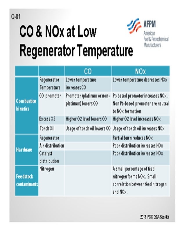
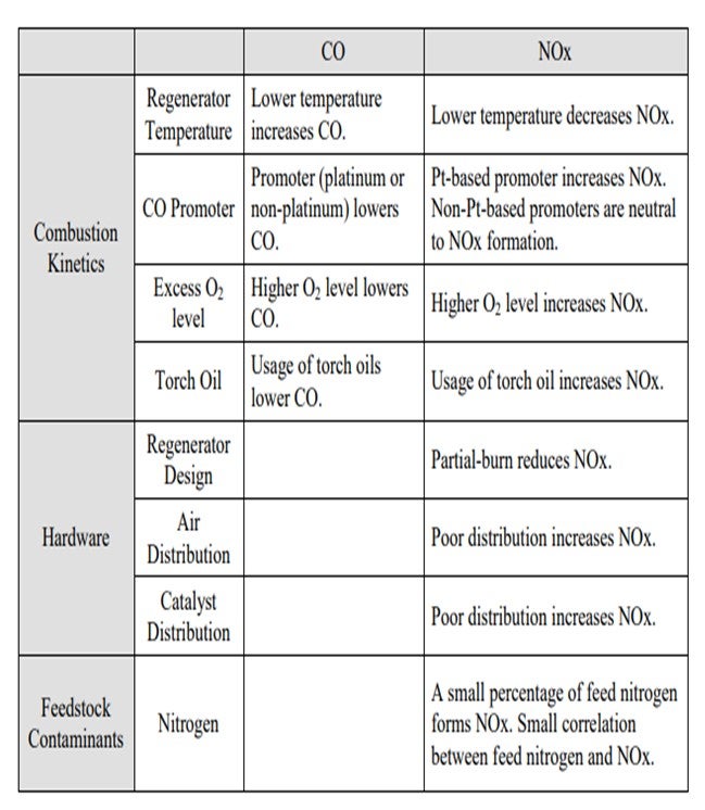
Jeff described many of these aspects, but I thought it would be worthwhile to summarize all of the factors into three main categories. One is, obviously, the combustion kinetics. Second is the hardware of the actual generator design; and third, to a certain aspect, are the feed contaminants such as feed nitrogen. In terms of combustion kinetics, a lot of these items have been discussed multiple times in past panels, so I will just go over the basics and summarize them. The lower regenerator temperature increases the CO but decreases the NOx or NO2; the promoter lowers the CO. But in terms of the distinction between a platinum and non-platinum base, the promoters can be either increased NO2 or NO2 neutral. The higher O2 concentration lowers the CO and increases the NOx. Again, these are some of the factors that you can use to counteract the formation of CO and NO2.
BART de GRAAF (Johnson Matthey INTERCAT, Inc.)
All of the speakers mentioned that the low temperature does affect the CO oxidation and the formation of NOx. The nitrogen kinetics in the regenerator are not affected by the lower temperature. Nitrogen in coke can be converted into nitrogen in NOx, hydrocyanide, and ammonia. As was suggested, non-platinum combustion promoter can be used to steer the oxidation reactions from HCN and NH3 towards N2 instead of NOx. Partial-burn operation is one example where you can see that the CO concentration does affect high NOx. But at the same time, in a partial-burn operation, after the CO boiler, you frequently see a higher NOx level than you would have in a full-burn operation because of the high temperature oxidation in CO boiler.
KEN BRUNO (Albemarle Corporation)
I want to point out that Albemarle has a detailed answer in the Answer Book. But in summary, Albemarle’s non-platinum promoter, ElimiNOx™, provides high CO promotion, excellent afterburn, and minimal impact on NOx emissions.
ROBERT “BOB” LUDOLPH [Shell Global Solutions (US) Inc.]
If you are an oxygen enrichment operator or considering oxygen enrichment, this is your opportunity to raise your bed temperature at the same coke burning rate and shift the CO and NOx distribution within the bed. In turn, the control of NOx and CO emissions could improve.
MICHAEL WARDINSKY (Phillips 66)
We have done a lot of modeling around NOx and CO emissions for additive use. We have seen NOx emissions decrease with higher regen temperatures in almost all of the modeling cases. From our experience, we also know that the non-platinum promoters can increase NOx emission, although not as severely as a platinum-based promoter. We have moved partial-burn units from deep partial-burn to full-burn and observed the NOx emissions decrease substantially. I think it was from the gentleman from INTERCAT who mentioned that in partial-burn, you are releasing ammonia and HCN (hydrogen cyanide) off the regenerator in greater quantities than during full-burn operations. However, these reduced nitrogen species are combusted across the CO boiler to NOx, so your partial-burn units always appear to emit higher NOx emissions than operating in full-burn, even after accounting for thermal NOx generated in the CO boiler.
JEFFREY BULL (Valero Energy Corporation)
CO emissions will increase if the regenerator falls below a certain temperature threshold. That temperature threshold varies based on the regenerator configuration and the type of air distribution. In general, well mixed regenerators with longer residence times can be run at significantly lower temperatures before CO emissions increase compared to a poorly mixed regenerator with lower residence times. In the absence of a CO combustor promoter, large variations in CO2/CO ratios are observed. At the catalyst surface, it is believed that the ratio of CO2/CO is an intrinsic function of the temperature at the burning site (“Arthur's ratio”). However, the CO exiting the burning site may be further oxidized to CO2 at a rate dependent on temperature; CO, O2, and H2O partial pressures; active metals on the catalyst; carbon/oxygen distributions within the fluidized bed; and even the catalyst presence.
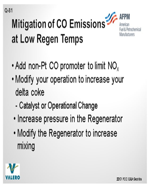
To mitigate CO emissions at low regenerator temperatures you can:
• Add non-Pt (platinum) CO promoter to limit NOx,
• Modify your operation to increase your delta coke (catalyst or operational changes),
• Increase pressure in the regenerator, and/or
• Modify the regenerator to increase mixing.
The amount of NOx emitted from the regenerator is highly dependent upon several variables such as mode of operation, regenerator style, excess O2, promoter concentration, coke distribution, feed N2, and dense bed temperature. Studies have shown that about half of the feed N2 goes to coke on catalyst, but only a small portion of the N2 in coke goes to NOx. It is believed that the NOx emission is limited by the reaction of CO + NO to form N2 and CO2. Thus, when Pt CO promoter is added to a unit, CO is converted to CO2 so quickly that there is less CO available to react with the NOx; so NOx emissions increase. We do have experience with a regenerator that is in true countercurrent flow, and the operator is able to run at low NOx levels with platinum promoter in the unit. In a partial-burn operation, there is always CO available to react with the NOx formed; so, emissions are lower. Good coke and air distribution are important so that concentrations of CO, O2, and NOx are evenly distributed throughout the regenerator.
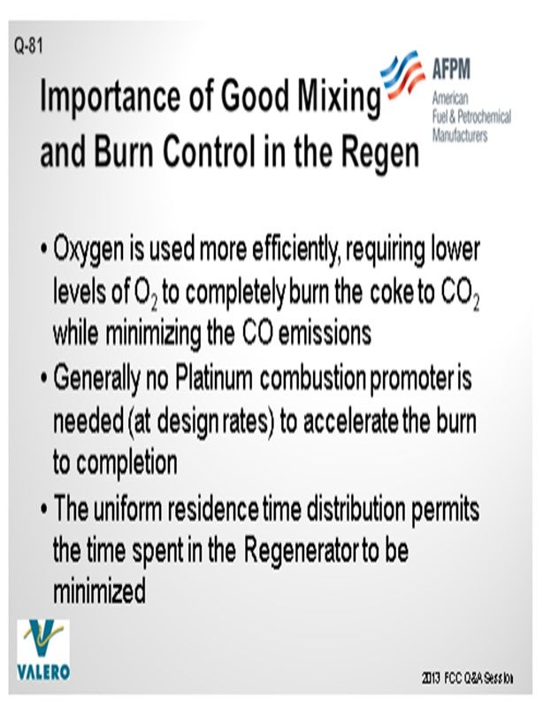
The results of the better, more efficient control of the burn zone in a regenerator are that:
• Oxygen is used more efficiently so that lower levels of excess oxygen are required to completely burn the coke to CO2 while minimizing CO emissions.
• Generally, no Pt combustion promoter is needed (at design rates) to accelerate the burn to completion.
• The uniform residence time distribution permits the time spent in the regenerator to be minimized.
Due to the interaction between CO and NOx in an FCC regenerator, testing should be conducted for your individual regenerator to determine the “tipping point” where a reduction in excess O2 causes CO emissions to increase dramatically. Running at an excess O2 slightly higher than the “tipping point” provides a baseline NOx that you can expect for your unit. If this level is too high, then you will either need to modify your regenerator for better mixing or use an alternate method of NOx reduction like LoTOx™, WGS+™, CONOx™, or an SCR. We have four LoTOx™ applications, one WGS+, one CONOx™, and one SCR in our system. In some cases, a catalyst additive can reduce NOx, but we have limited experience with this application.
STEVE GIM (Technip Stone & Webster)
Why lower regenerator temperatures? Let us first examine some of the factors leading to lower regenerator temperatures: first, better feedstock qualities (such as lower Conradson carbon), lower nitrogen, and metals. Second, lower operating severities, such as lower reactor outlet temperature and lower catalyst activity, will lower regenerator temperatures. Third, catalyst regeneration, including full versus partial-burn, CO promoters (platinum-based or non-platinum-based), and supplemental oxygen turned off are additional options.
Factors Directly Affecting CO and NOx: Many of these directly affect the formation of both CO and NOx in the regenerator. Some of these factors influence the formation of these two species in opposite direction. I have summarized these factors into three categories and their directional changes of the CO and NOx. Many of these items are obvious and have been extensively discussed in the past panels, but I thought it would be a good summary.
Interactions Between CO and NOx: Reductant-like CO converts NOx to elemental nitrogen in the presence of O2. Lower regenerator temperature can be the direct result of higher CO to CO2 ratio in partial-burn units, which in turn will lower the NOx.
CHRIS STEVES (Norton Engineering)
The impact of low regenerator temperature on CO and NOx emissions can be very unit-specific, depending especially on regenerator design and the distribution of air and coke in the regenerator. In full-burn units, operation at low regenerator temperature will generally result in higher CO emissions and lower NOx emissions. The use of CO promoter can help in reducing CO formation, but use of platinum-based promoters is well documented as increasing NOx emissions. Non-Pt-based promoters are widely used today to allow for control of CO (and afterburning associated with CO) while limiting NOx emissions.
RYAN NICKELL (Albemarle Corporation)
Though not directly stated, this question is most applicable to FCC units concerned with after-burn. Lowering the regenerator temperature can indeed lead to an increase in CO and NO to N2 and CO2. A platinum-based combustion promoter can be used to reduce CO emissions with excellent success. However, NO will increase as intermediates, such as HCN and NH3 (ammonia), are also oxidized by platinum. As a result, many refiners prefer a non-Pt-based promoter such as Albemarle’s ElimiNOx™. This additive provides high CO promotion activity but acts less on the aforementioned intermediates containing nitrogen. ElimiNOx™ provides excellent after-burn control and minimal impact on NOx emissions.
Year
2013
Process