Question 21: We are observing fouling of our feed/effluent exchangers that has impacted heat transfer and restricted feed. What are potential contributing causes and how can we mitigate?
ROBERT STEINBERG (Motiva Enterprises)
There are many things that can contribute to fouling of feed/effluent exchangers. Fouling can occur on either the feed or product side of the exchangers.
Possibilities sources of fouling on the feed side include:
• Dissolved O2. Oxygen can get into feeds if they come from a tank that is not N2 blanketed, this is especially likely if feeds have been imported from another site via a barge. Oxygen can also be present if a feed come from a vacuum tower with an air leak. Corrosion inhibitors or oxygen scavengers injected into the feed as far upstream as possible may help. The best method to remove oxygen is to add an O2 Stripper on the stream that contains oxyg
en.
• Caustic. Small amounts of caustic that was not water washed can lead to severe fouling.
• Particulates, scale, corrosion particles. FeS scale is often found in refinery streams. If the source is known, corrosion inhibitors may be able to reduce the amount of scale. Good feed filters may be able to remove some of the scale but FeS particulates can be small enough to pass through most feed filters.
• Dirty feed. Cracked feeds, especially coker gasoils, tend to be dirty and have small coke particles. Good filtering is essential. If not done at the upstream unit it needs to be done on the hydroprocessing unit. It is often a good practice to filter both places in case one of the filters is bypassed.
• Salt in Feeds. If crude oil is not properly desalted there can be salts left in heavy feeds. Salts from other sources can also be present at times. A water wash or a desalter can remove salts.
• High temperatures. High skin temperatures tend to increase fouling. High temperatures may be unavoidable when exchanged against reactor effluent, especially in the hotter shells. An exchanger design that increases velocity and promotes turbulence on the feed side will increase the heat transfer coefficient and reduce skin temperatures. Injecting hydrogen upstream of the exchanger will help.
• Low velocities. Lower velocities in the exchanger reduce pressure drop but lead to higher skin temperatures, make it easier for particulates to stick to tube surfaces and increase fouling. Injecting hydrogen upstream of the exchanger will help. Recycling hydrotreated product when the unit is turned down will maintain higher velocities in the exchangers.
• Cracked feeds. Cracked feeds have olefins and sometimes di-olefins which can polymerize and are more prone to fouling. Cracked feeds can be a particularly severe problem if dissolved oxygen is present. A selective hydrogenation unit or reactor can be used to saturate di-olefins at a relatively low temperature upstream of the main reactor before the feed gets hot enough for severe fouling to occur.
• Asphaltene precipitation. This is normally only an issue with resid units. Mixing different feeds, especially a lighter more paraffinic feed with resid, can create incompatible mixtures and cause asphaltene precipitation.
Reactor effluent is normally cleaner than reactor feed. Olefins get saturated and dissolved oxygen gets converted to water in the reactor. The reactor effluent will always have hydrogen which tends to keep velocities high. However, there are some possible sources of fouling on the reactor effluent side:
• Salt precipitation. H2S, NH3 and HCl are normally present. These form ammonium chloride (NH4Cl) and ammonium bisulfide (NH4HS) salts when temperatures fall below the salt formation point. The salt point is dependent on the operating pressure and concentration of H2S, NH3 and HCl. Salt point curves can be found in API Recommended Practice RP-932B Design, Materials, Fabrication, Operation, and Inspection Guidelines for Corrosion Control in Hydroprocessing Reactor Effluent Air Cooler (REAC) Systems. Typical precipitation temperatures are in the 300-400°F range for NH4Cl and around 100°F for NH4HS. In addition to fouling, these salts can be extremely corrosive if water is present. Dry salts are not corrosive but an intermittent water wash may be needed to remove them once fouling occurs.
• Polynuclear aromatics. This is normally only an issue with hydrocrackers, especially the 2nd stage of a two-stage recycle unit. If conversion is too high the PNA concentration can get high enough that they become insoluble in the oil. The lighter cracked products can cause PNA’s to precipitate in exchangers as the effluent cools and more of the naphtha range material condenses.
JOE RYDBERG (CITGO)
In our recent experience, fouling on the “feed side” of the feed/effluent exchangers in Naphtha units is due to corrosion products (Fe) entering with the feed, and processing recycled Naphtha’s particularly from LPG Caustic Disulfide separators. The recycled naphtha’s can have higher levels of Sodium and Salts (likely amine degradation products that build up in the caustic).
Other causes can be contamination of cracked stocks into the virgin stocks system. Exposure to oxygen will cause gum formation. Crude supply sources have unknown diluents. Refineries are now collecting more material from various refinery sources and rerunning as slops, for example introduction of flare gas recovery liquids, reprocessed as slop oil; re-processing/chemical cleaning liquids pumped to slop system.
Use of chemical additives (organic dispersant, antipolymerant, oxygen scavengers) can be used and are used within CITGO to mitigate fouling. Proper tracking of heat exchanger fouling is important and can aid in scheduling cleanings (requiring unit shutdowns) outside of turnarounds, during catalyst change-outs, etc. When dealing with especially challenging feeds and / or extending cycle length goals, installation of spare feed/effluent heat exchangers could be value added approach
Effluent side fouling typically is caused by inadequate water wash, presence of NH4Cl in addition to FeS. HCl can also react to create additional FeS in the presence of H2S.
ERIC LIN (Norton Engineering Consultants, Inc.)
In a hydrocracker with liquid recycle (could be single stage recycle or two-stage recycle), there exists the possibility of HPNA (Heavy Polynuclear Aromatics) buildup at the bottom of the fractionator. Although the overall conversion will decrease, the best solution is to have a dedicated bleed stream out of the unit (FCC is a typical destination) to prevent this buildup. High asphaltenes in the feed are usually a sure sign of HPNA production.
In a residue hydrocracker, the existence of sediment can cause similar fouling in these exchangers. Sediment can typically be mitigated with the use of slurry oil as a cutter (much easier to acquire for units that also have an FCC nearby).
SAM LORDO (Consultant)
Fouling in the circuit ahead of the furnace and furnace can be caused by inorganic solids, or polymerization of feed components (organic fouling). Mitigating fouling from inorganic solids, such as iron sulfide and other corrosion byproducts, sand and silt (from imported feedstocks) is primarily done using feed filters. The pore size is best at 1-5 micron. The filter can be cartridge style, sand filters. Some filter arrangement would have backwash capability.
Fouling downstream of the reactor may include ammonium chloride (NH4Cl). Typically, a well-designed Waterwash is used. The use of salt dispersants are also applicable where Waterwash is feasible
Organic fouling could be from:
• Stream that contain olefinic/diolefinic components which when exposed to elevated temperatures ass found in the hydroprocessing units
• O2 contamination of feed or feed component streams
Mitigation of this source of fouling can be done using an appropriate chemical additive, such as dispersant and/or antiploymerant.
MICHAEL PEDERSEN (Honeywell UOP)
Most hydroprocessing catalysts require a conditioning period at start of run to allow the active sites to stabilize. One aspect of this process is the common industry practice to avoid processing cracked feedstocks during the first few days of operation. Prior to conditioning, fresh catalysts have a high tendency to generate excessive coke when operated with reactive feedstocks or at normal unit operating severity. A short period of mild operating conditions can pay big dividends in overall catalyst cycle performance while high severity operation at start of run can have substantial negative impact on apparent catalyst activity and cycle length. In general, catalysts that are claimed not to require conditioning have been artificially inhibited prior to delivery.
Hydroprocessing catalysts encompass a wide variety of formulations, so a general set of conditioning guidelines is not applicable. For a specific catalyst system, instructions from the supplier should be followed.
SIMERJEET SINGH and RAJESH SIVADASAN (Honeywell UOP)
Fouling of feed/effluent exchangers in hydrotreating units is a common problem leading to throughput losses, increased energy consumption, unit downtime and maintenance expenses for exchanger cleaning. Fouling happens due to changes in feedstock quality, exchanger temperature, fluid velocity, degree of vaporization and exchanger configuration leading to formation of hard carbon deposits (coking), deposition of undesirable polymers (polymerization) and corrosion products.
For Coker Naphtha Hydrotreater:
• Feed quality issues:
Coker naphtha (CN), by the nature of thermal cracking reactions, contains free radicals, which react with diolefins and olefins to form oligomers and polymers. By itself CN presents a fouling problem in a NHT, however when combined with stored SRN there exists the potential for significant fouling. Storage of CN prior to processing can have disastrous results, as the combination of diolefins, free radicals, and oxygen (peroxides) can lead to rapid fouling on the feed side of the combined feed exchanger (CFE), the NHT charge heater, and the NHT reactor. This fouling can be serious enough to cause premature pressure drop increase along with loss of heat transfer due to fouling in a matter of days if not hours. The downtime associated with addressing this fouling costs the refiner time and money.
The highly reactive diolefins in CN are the four carbon and five carbon species, at the front end of the boiling range. Longer chain diolefins tend to be reactive, but less reactive than the short chain diolefins. Simply increasing the initial boiling point of CN (reducing the quantity of light diolefins) may reduce the tendency of CN to cause fouling. When cracked stocks with significant diolefin concentrations are present, it is UOP’s practice to include a diolefin saturation reactor as a first, low temperature reaction stage in a two-stage reactor system. In this reactor, most of the diolefins are saturated. This reactor is located in between CFE shells and its position is selected such that the inlet temperature is in the range of 320-370°F.
• Design considerations:
o Feed tank blanketing
o Design of feed tanks (Fixed/ floating roof)
o Hydrogen Injection to preheat exchangers
o “Over-Sized” exchangers for clean duty
o Exchanger velocities
o Dry Point location
For VGO HDT:
• Feed quality issues:
o Fouling is also experienced in units that run straight run feed only, so it is not just a phenomenon that requires cracked olefinic feeds.
o Fouling from asphaltene precipitation.
• Design considerations:
o Same design considerations as coker naphtha HDT except the dry point location.
o Thermal cracking of feed VGO in feed effluent exchanger can be of main issue if separate feed heating is being used as design feature over combined feed heating.
• Fouling Mitigation Strategies:
Many methods exist for managing fouling. The costs of these methods vary, as does their effectiveness. In order to choose the most effective method for managing fouling, an understanding of the source of foulant precursors should be established. Analytical methods are available that can be used to characterize a feed for gums, asphaltene or stability in the presence of oxygen. While these methods may or may not provide a complete solution to exactly where the fouling problem comes from, they may help to characterize the different feeds at a given site and help narrow down the probable root cause.
• Avoid oxygen contamination of feed.
Direct feeding – Supply feedstock to hydrotreater from upstream unit without using intermediate tankage.
Benefits:
o Eliminates residence time in intermediate tankage, thus minimizing formation of other free radicals.
o By far the cheapest solution and reduces working capital.
Risks:
o Lacks flexibility to accommodate swings in feedstock rate and unit outages.
Tank blanketing – If tanks must be used, they should be blanketed. Nitrogen is the best blanketing gas owing to its reliably low O2 content and ease of venting to atmosphere. Gas blanketed internal floating roof tanks are most effective in minimizing oil contact with O2 and evaporation losses to blanket gas.
Benefits:
o Commercially just as effective as direct feed and overcomes all the limitations.
o O2 cannot react if not in system, therefore should reduce foulant generation.
Risks:
o Cannot impact O2 brought in with import through other feeds
o Choice of correct seal for floating roof and its periodic checking and maintenance.
• Remove Oxygen from Contaminated Feeds.
Oxygen Stripper – Strips out free O2, including import O2 and removes the potential for further formation of peroxides. Common scheme is for ambient temperature hydrogen stripping of the feed to fuel gas system.
Benefits:
o Only feed streams exposed to O2 need to be stripped.
o Maximizing direct feed to the unit in combination with stripping the small O2 contaminant stream is generally more economical than stripping the complete feed stream.
Risks:
o Residence time, particularly in imports, may result in some polymer reaction occurring.
o Expensive option in terms of equipment, and is not so effective if the peroxides/ polymer has already been formed upstream of the stripper.
Injection of anti-oxidant chemical – Antioxidant chemicals have been used with a degree of success in some locations.
Benefits:
o Act as chain stoppers that react preferentially with O2 and peroxides, making them unavailable to take part in free radical polymerization reactions.
Risks:
o Although chemical treatment can help, it is not always successful and it tends to be most effective when the antioxidant is dosed into the upstream unit rundown ahead of the storage tank.
• Remove foulant/prevent laydown.
Hydrogen treat gas injection – Inject hydrogen treat gas upstream instead of downstream of preheat exchangers.
Benefits:
o Hydrogen gas increases turbulence and can also help to reduce polymer formation reactions.
o For VGO HDT hydrogen injection especially for units with separate heating of VGO will prevent thermal cracking of VGO.
o Avoid dry point in exchanger areas where the feedstock is completely evaporated towards dryness as severe fouling may happen. Polymer and gum tends to build up on the shell-side behind baffles, because of relatively stagnant zone. Evaporation of feed leaves less liquid solvent for the gums and gums get deposited. Most severe at the liquid dry point.
• Modify exchanger design – Modify exchanger internals, maintain high velocities in exchangers, appropriately oversize exchangers to lower high tube wall temperatures below the critical temperature required for coking or polymerization.
Parallel exchanger – Flexibility for bypassing and cleaning.
Benefits:
o Clean all exchangers on-the-run, extra exchangers mean no loss of throughput to clean.
Risks:
o No reduction in rate of fouling.
o Additional design features required (such as PRV’s) to safely by-pass/isolate exchangers.
• Anti-foulant chemical injection.
Benefits:
o A reduction in the rate of fouling.
Risks:
o Fouling mechanisms will still occur, probably downstream.
• Prevent corrosion
Corrosion resistant tube metallurgy – select appropriate tube metallurgy to prevent formation of corrosion products that aid the process of foulant formation such as naphthenic acids or high TAN feeds.
Benefit:
o Easy to implement for new unit and revamp of existing unit.
Risks:
o May not be the best solution as metallurgy upgrade is expensive and components other than tubes can still provide corrosion products to aid fouling.
IHSAN RAAD (Shell Catalysts & Technologies)
There are several types of fouling in Hydrotreating feed/effluent exchanger units, the three most common types in the industry are:
1. Inorganic particulates.
2. Organic deposits.
3. Ammonium salts.
Each type of fouling has its own characteristics and deposition locations. Knowledge of the type of fouling and the underlying deposition mechanism is essential to tackle the fouling problem. This can either be done by eliminating the root-cause, or by selecting a fit-for-purpose and cost-effective abatement approach.
1. Inorganic particulates: Inorganic fouling is mainly caused as a result of iron sulfide, sodium or coke fines that can either be carried from upstream units or generated in-situ in the preheat exchanger network. These foulants are:
• Iron Sulphide (FeS) and Iron Oxide (FeO, Fe2O3): Scales of iron oxide (FeO, Fe2O3) and iron sulphide (FeS) are generated as corrosion products within the unit itself but can also come from upstream units, intermediate storage and transport from well to refinery. Important corrosion sources are furnace tubes (hot sulphur corrosion), the CDU overhead condenser and the reactor effluent air cooler. Iron corrosion products in VGO’s are also associated with processing of naphthenic crudes.
• Sodium (Na): Na can come from brackish or salty cooling water (i.e. leaking heat exchangers) or from processing water-containing slops or imported feeds. Sodium in combination with iron has been known to promote coke formation under conditions of high temperature and low pp H2.
• Coke (C): Coke fines can be entrained from VBU’s and cokers, which cause mainly fouling of the feed side of the feed/effluent heat exchangers, furnace tubes and the top beds of reactors. VGO hydrotreaters might also experience coke formation due to a poor separation in the upstream HVU.
2. Organic deposits: The organic foulants are primarily gums formed as a result of processing cracked material and accelerated if the material is exposed to oxygen at any time. The types of foulants are:
• High di-olefin Content: Di-olefins (molecules containing (multiple) double bonds) are mainly found in product streams from (thermal) cracker units but can be present in other streams as well. At the right temperature level (~400-500°F) they polymerize readily to form gum-like substances often showing up as greyish flakes on the FEHXers. The rate of this reaction increases at higher temperatures, making the FEHX especially vulnerable. Elimination of feed streams with high di-olefin content is an easy way to reduce fouling but may not be preferred economically. If long periods of operation with high di-olefins content are expected, an option to avoid high fouling rates could be the installation of a low temperature di-olefin saturation reactor.
• Oxygen in Feed: Oxygen can form a range of different molecules when it is dissolved in a hydrocarbon stream (e.g. peroxides, carboxylic acids, aldehydes and other oxygenated compounds). Amongst other problems, these molecules can initiate polymerization reactions to form gums. Oxygen can enter a feed stream in several ways, including but not limited to air-breathing storage tanks, marine or surface transport vessels, leaks in equipment operating in sub-atmospheric pressure or faulty pump seals. One common point for oxygen to enter feedstock is during storage. Feed streams can be routed directly from unit to unit to avoid intermediate tank storage. Another option is to put in a bypass jump-over on the tank such that only the extra feed goes to tankage and the rest will bypass and go directly to the hydrotreater. All tanks used for storing hydrotreater feed should be nitrogen blanketed, also for straight-run feed. If this is not done, gum formation and other side reaction might happen in the tank itself. Other mitigation is to run it through a stripper, fractionator or distillation unit before introducing it to the unit in order to strip away both dissolved oxygen and the oxygenated compounds, like peroxides. A last option that is used to avoid oxygen related fouling is by injecting anti-oxidants into the feedstock. These compounds are only effective when they are injected prior to the feed stream coming into first contact with the oxygen. So, it should be ideally be injected at the source prior to transportation to site or send to storage. Also, good mixing of the anti-oxidant with the hydrocarbon streams is essential. Only then can they prevent gum formation during storage.
3. Ammonium salts: There are several types of salts that can formed in the effluent exchanger.
• If ammonia and HCl are present, ammonium chloride may deposit directly from the gas phase. The sublimation point in the process depends on the operating conditions (pressure and temperature profile) but also on the concentrations of ammonia (generated from hydrogenation of nitrogen compounds) and chlorides. Main locations of deposition are the feed/effluent heat exchangers (effluent side), the air cooler and recycle gas compressor valves. In the dry state this salt is not corrosive, but in areas where the water dew point is approached, the deposited NH4Cl salt will become moist and can be very corrosive (NH4Cl salts are hygroscopic, therefore the stream temperature must be maintained 15-20 C above the water dew point to assure dryness). Furthermore, apart from the danger of excessive corrosion, NH4Cl deposition can drastically increase the pressure drop and to decrease the effective duty of feed-effluent heat exchangers.
• Like Chloride, organic bromide will convert to hydrogen bromide after hydrotreating and then react with ammonia to form ammonia bromide salt in the exchanger.
• Ammonium bisulphide (NH4HS) hydroprocessing reactors convert sulphur and nitrogen compounds in the feed to H2S and NH3. On cooling, these two compounds react to form NH4HS. In the absence of water, NH4HS deposits to form a crystalline solid that can cause plugging of the reactor effluent air cooler. This will occur at relatively low temperatures, 10-30°C. If the dew point of water is reached in the effluent air cooler (or water cooler) or if insufficient wash water is injected.
In summary, foulants are typically found on the feed side of the preheat exchangers include various gums or polymers, iron sulfide, and salts. The organic fouling due to gums and polymers results from the polymerization of unstable species in the unit feed. Therefore, in order to determine the risk of organic fouling for a particular feed stream, detailed analysis of the feed is required to determine the problematic species in order to evaluate the fouling propensity and mitigation strategies. Another key factor to consider is the oxygen content of the feed stream as this can promote the polymerization of various unstable compounds, particularly olefins. Therefore, it is a good practice to exclude oxygen from feed storage tanks using a nitrogen blanket. However, this method is ineffective with streams already exposed to oxygen. The inorganic fouling is mainly caused as a result of iron sulfide that can either be carried from upstream units or generated in-situ in the preheat exchanger network. Identifications of the contaminants source and mitigations are key to eliminate the inorganic foulants.
SERGIO ROBLEDO (Haldor Topsoe, Inc.)
To answer this question, we need to differentiate between feed-side fouling and effluent-side fouling. Potential causes and mitigations will depend on which side is experiencing the fouling.
Feed-side fouling in your F/E exchangers can be the result of:
• Olefins
• Oxygen
• Particulates
Olefins/Oxygen
Olefins are normally introduced with cracked stocks in the feed. Typically, olefin gumming happens at lower temperatures (300 – 350 °F). Gums formed from peroxides, as a results of oxygen contamination of straight run feed, usually occurs at >400 °F.
In the case of coker naphtha, conjugated diolefins are present which are highly reactive species. In the presence of very small amounts of oxygen, or at elevated temperatures above 450 °F, these molecules will radically polymerize to form gum that can foul exchangers causing poor heat transfer as well as high pressure drop. If the feed contains significant quantity of coker naphtha then these Diolefins must be removed to prevent gum formation.
The coker naphtha should preferentially be sent to directly from the coking unit to the hydrotreater to prevent contamination with oxygen. Even straight run stock, which may be part of the feed component, must be prevented from contacting oxygen by storing the feed in a nitrogen blanketed storage tank.
Even with strict adherence to avoid feed contact with oxygen, the diolefins in the coker naphtha can polymerize at elevated temperatures. A dedicated saturation reactor operating in the range of 300 °F to 450 F will ensure that these highly reactive species are removed from the feed before polymerization can take place. Once the diolefins are removed from the feed then the feed can be heated to the required temperature for the required operating scenario.
Keep in mind that even though cracked stocks are not fed directly to a unit, there is potential of introducing cracked stock in sites that process slop in their Crude unit.
Particulates
Particulates, at high enough concentrations, in conjunction with low tube velocities, can result in these particulates settling out and plating on the surface. If no filter is present, then plans should be made to engineer and install a filter system to reduce the amount of particulates present in the feed. There are also companies that offer tube inserts to reduce the likelihood of particulates settling out and plating on the tube surface, preventing a loss of heat transfer.
Even with filters and tube inserts, if any gumming is taking place in the exchangers, then any small amount of particulates present will be picked up by the gums formed.
Examples in industry where fouling occurred on the feed side are:
• Cracked stocks blended with Canadian crude coming down the pipeline. These formed gums with oxygen and fouled the exchangers.
• Crudes from Venezuela blended with cracked stocks.
• Virgin jet was exposed to oxygen and fouled in exchangers operating >400 °F (this happened in multiple units).
o Similar example with natural gasoline.
As mentioned before, preventing oxygen ingress via direct, hot feed of cracked stocks to the unit, along with floating roof and/or nitrogen blanket on tanks is imperative. Tube inserts are also a viable option to prevent fouling where tube velocities are low enough allowing particulates to drop out in the exchanger. Most importantly, quality control is paramount in preventing this, or reducing further loss in performance. Examples of actions are:
• Notify the shipper and have the diluent stream changed.
− What is the crude source? Are there potential cracked stocks coming down the same line? How about Canadian crudes?
• Notify crude supplier about the poor quality.
• Install an oxygen stripper.
− Done for the virgin jet example.
• Install nitrogen blanket on feed tank or change to floating roof tank.
• Inject antioxidants into the tanks (mixed results).
• Bypass tank and go hot (direct) to the unit.
As for effluent side fouling, this is typically the result of NH3Cl (salts), which are the result of high levels of Cl in the feed. A water wash should be installed to remove these salts, and continuous is recommended versus intermittent.
• A licensor can help calculate where the water should be injected.
– Need to inject enough water and at the right spot to keep it as a liquid and not vaporize
– Liquid water will wash out the salts while steam will not
– Licensor can calculate where the dry point will occur and how much water needs to be injected
• Many examples of where water wash helps
– If done at the right spot with the correct amount of water and at the right temperature
• Boiler fouling
– Water treatment company can help with this
There is also a very good P&P this year covering reactor effluent diseases jointly presented by Flint Hills Resources and Marathon. Please plan to attend to learn more.
Year
2019
Submitter
Process
Question 36: What are your primary indicators that a coker furnace spall is complete? What steps do you take to optimize the efficiency of spalling?
GAMBOA-ARIZPE (CITGO Refining & Chemicals, L.P.)
A cautionary foreword: Online spalling of furnace heater tubes is not suitable for every heater design. It is necessary to consult with your furnace licensor or manufacturer to determine if online spalling practices are compatible with the heater designs installed in your respective facilities. There will be a more complete answer in the final transcript, including a more detailed discussion on the practice of delayed coker furnace spalling and the factors used to determine when the decoking operation of the furnace is needed. The verbal answer will only address the descriptive metrics currently being employed to determine when a furnace spall is considered ‘complete’. Technically, however, the primary question here is a difficult one to answer, because the completeness of a spall can only be determined post-spall with the furnace back online and after tube wall temperatures are measured; and to a lesser degree, after the heater pass pressure drop on normal oil flow has also been measured. Fortunately, the completeness of a spall can also be based on previous experience with a particular furnace and can be managed procedurally. That is the basis on which I will attempt to answer this question.
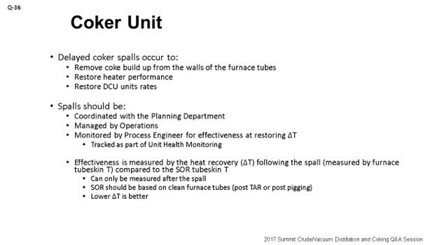
CITGO Petroleum Corporation operates four delayed coker units amongst its three U.S.-based refineries. Three out of the four units incorporate routine spalls for their respective coker furnaces as part of a broader operating strategy to optimize effectiveness of their overall furnace operation. The fourth delayed coker unit relies primarily on ‘piggings’. The benefits of online spalls versus steam/air decokes versus piggings will vary depending on the logistics of a facility, as well as on the heater’s mechanical configuration and its design. The decoking effectiveness of the three methods is also different. All methods, however, fundamentally aim to remove as much of the fouling coke layer that builds up along the interior surface of the furnace tubes as is possible during the operation.
The buildup of coke within coker furnace tubes is intrinsic to the delayed coking process due to the nature of vacuum residue material once it becomes exposed to the relatively high temperatures that are required by the process (greater than 850°F). While the buildup of coke cannot be totally averted, the rate of this buildup can be managed, depending on the heater design and other factors. The thickness of the accumulated coke layer can be generally inferred by monitoring and trending the furnace tube wall temperatures. Higher tube wall temperatures are indicative of thicker coke buildup because the deposited coke layer has lower thermal conductivity than the metal substrate of the furnace tubes. In effect, the coke layer acts as an insulating barrier that restricts the transfer of heat from the fire box into the process stream, which then allows the metal temperature of the tubes to increase.
Over time, the tube wall temperatures increase as the coke layer thickens. The sections of the heater that begin to experience faster coke buildup also shift with time as more and more tubes begin to experience lower heat transfer. This dynamic is caused by the need to keep the target coil outlet temperature (COT) relatively constant to maintain viable C5+ liquid yields and because the total heat flux across the heater [for a fixed surface area and a known dT (delta T; ∆T; temperature differential)] is also relatively constant. In other words, the gradual reduction in heat transfer efficiency across some of the process tubes forces the furnace to be fired at increasingly higher rates. This firing shift increases the localized heat fluxes in other sections of the heater to meet the specific COT that is dictated by the operation.
Removal of the coke layer at some routine maintenance interval improves the furnace’s overall heat transfer efficiency because it eliminates the insulative barrier that prevents the heater from meeting those COT targets at lower firing rates. Because of this dynamic, the tube wall temperatures tend to increase logarithmically over the course of a run until the coke layer is again removed. The run-length of this recurring operation must be optimized to maximize the refinery’s profits while ensuring that the long-term reliability of the equipment is not compromised.
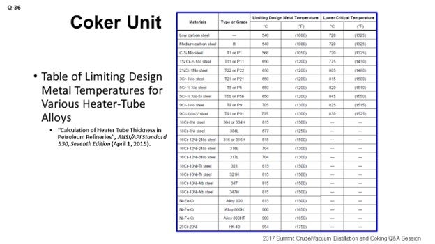
Ultimately, the delayed coker furnace is decoked on an as-needed basis to prevent operation that could produce tube wall temperatures above the limiting design metal temperature of the respective alloy of the furnace tubes [as defined by API 530 (Table 5) or an equivalent table (ANSI, ASME, etc.); see my second slide entitled “Table of Limiting Design Metal Temperatures for Various Heater-Tube Alloys”]. The timing of a decoking operation is, therefore, dictated by the need to manage the reliability of the equipment, particularly to avoid encroaching the mechanical limits of the furnace tubes themselves; especially, long-term operation at the elevated temperatures. Equally important, an alloy’s critical temperature should generally never be exceeded as this could result in changes to the alloy’s microstructure. Note: Per API 530, “Other considerations can require lower operating temperature limits, such as oxidation, graphitization, carburization, and hydrogen attack.”
The API 530 limiting design metal temperature is not necessarily the strict driver for the end-of-run (EOR) tube metal temperature, although one could say it is good practice not to exceed it. The real driver for the EOR temperature is an economic optimization question: If a refiner chooses too high of an EOR temperature, then he or she will have to retube the heater excessively/ often; and if the refiner chooses too low of an EOR temperature, then he will have to decoke excessively/frequently. The short-term mechanical integrity limit for a typical coker furnace tube is appreciably higher than the typical EOR temperature. The tube geometry is a factor as well. For a thick-walled tube, the stresses are lower so higher temperatures can be tolerated. At CITGO, the online spalling operation was introduced as a viable decoking practice as early as 2001, with conceptual preparation going as far back as 1999. The written procedures themselves have been optimized at each respective facility via post-spall performance-based evaluations. Trial-and-error adjustments, both to the duration of the overall spalling and to the variable knobs of key procedural steps, have also been modified and incorporated over the years to produce the current procedures being employed today. There is some procedural rigidity for certain steps, but experience has also resulted in producing procedures which allow for some flexibility in other steps. The success of the online spalling operation depends on the combination of various factors. But in a broader sense, four gates must be cleared for the spalls to adequately remove sufficient coke buildup and restore heater performance.
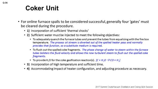
In a general sense, the term ‘spall’ describes the physical action in which chips or fragments are splintered and broken off of a larger solid body. There are several mechanisms that can produce a spall. In the context of the delayed coking process, however, the aim of furnace spalls is to break the coke layer off of the interior walls of the furnace tubes. This dynamic is produced by heating and contracting the furnace tubes in an alternating fashion over a relatively short time span to thermally shock and alter the fixed volume in the tubes themselves. Since the coefficients of thermal expansion of the metal substrate and the fouling coke layer are significantly dissimilar, the two layers grow and contract at different rates, which causes the physical detachment of the coke layer from the metal surface. The objective of thermal shock is to physically break the coke layer by using the force that is produced by thermal stresses to fracture the foulant layer. The first gate that must be satisfied in the spall, therefore, is to ensure that sufficient thermal shocks are incorporated during the procedure. Some are incorporated on the frontend of the spalling procedure, while others are incorporated on the backend of the spall.
During the spalls, boiler feedwater is lined up to the spalled heater pass, usually upstream of the convection section. Water addition serves three purposes, and I have them listed under the second bullet point in the slide. The three purposes are to:
-
Adequately quench the furnace tubes and prevent the tubes from equalizing with the fire box temperature. The process oil stream is diverted out of the spalled heater pass and normally provides that function, so a substitute medium is required.
-
Flush out the spalled coke fragments. The phase change of water to steam within the furnace tubes bolsters the fluid velocity and allows the now turbulent steam to flush out the spalled coke fragments.
-
Provide H2O for the coke gasification reactions.
The second gate that must be cleared is that sufficient water must be injected into the spalled heater pass to provide these three necessary functions. Water addition should be ratably controlled to target specific zones along the spalled heater pass and can be done by monitoring the progression of two wall temperatures in those specific sections over the course of the spall. Note: Boiler feed water or condensate is typically used as the source water because it needs to be free of inorganics/minerals (calcium, magnesium, sodium, etc.).
A combination of high temperature and time is needed to clear the third gate. The optimum value for both of these parameters must be determined through local experience while remaining within the temperature limits of the affected tube alloys. Procedurally, the time factor – or ‘length of hold’ step – should not be too rigid, given the fact that effective spalls can be performed to varying hold step lengths and dependent upon the morphology of the foulant coke, which can change and also be dependent on the feed slate. The combination of high temperatures and high steam velocities is required to micro-spall the coke layer via erosion and gasification reactions (where the steam can directly react with the coke to produce H2 and CO). The time factor simply provides a window for these two mechanisms to occur. The bulk of the coke removal during a spall operation may actually occur from micro-erosion and coke gasification, given the gradual change in tube skin temperatures that is typically observed during spalls.
The fourth and final gate is more or less dependent on the heater design. Typically, a heater pass is spalled individually while other the heater passes remain on oil. This approach creates the possibility that the spalled heater pass may be affected by a neighboring sister pass. The fourth gate simply acknowledges the impact that a sister pass can have on the spalled heater pass and accounts for its heat input. Simply stated, a sister pass may need to have its respective coil outlet temperature target lowered prior to the introduction of oil into the spalled heater pass so that the combined firebox heat fluxes do not adversely affect the spalled heater pass in an acute fashion. Experience has taught CITGO that as much as half of the spalling benefit can be squandered from the onset if the effect of the sister passes is not taken into account. Along the same vein, another consideration to preserve the benefits of a spall prior to the conclusion of the spalling operation – and once oil is reintroduced into the pass – is to ensure that the core outlet temperature targets for the spalled heater pass be ramped up slowly. This precaution is needed to prevent higher flux conditions during the period when the oil flow in the spalled pass is not yet sufficiently high to properly quench the tubes.
It should be noted that spalling operations are not as effective on the process convection tubes, because even the minimum water addition requirements may over-quench and prevent the convection tubes from getting hot enough for the spalling mechanisms to work as effectively. Fortunately, the process convection tubes generally do not coke up as severely or as rapidly as the furnace’s radiant tubes. Eventually, however, the loss of heat transfer along the process convection section can become limiting enough and impose a higher duty load on the radiant section (leading to more accelerated heater pass coking rates in that section). Because of this ‘diminishing return’ dynamic, a heater that is normally decoked with online spalls will also need to incorporate a steam/air decoke or a pigging operation – roughly after every three or four spalls – to better restore the performance of the convection section.
In summary, sometimes short spalls are successful; sometimes they are not. Sometimes spalls with less water injection are successful; sometimes they are not. Sometimes spalls at higher temperatures are successful; sometimes not. Generally, however, if furnace tube wall temperatures can be uniformly reduced by 150 to 200°F post-spall, then the spalling operation can be deemed successful. This result will typically occur if all four gates discussed above are satisfied. Of course, there are a myriad of other factors one must consider with the spalling operation, such as effects on coke morphology, the coke cutting operation, some additional reliability considerations, and effects on the heater pass outlet manifold. These other factors usually do not affect the performance of the spall itself; they just need to be considered.
LÉGARÉ (Andeavor Martinez Refinery)
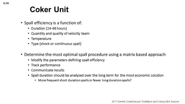
I will try to fill in some of the very few gaps that Héctor had in his talk. So, why is spalling efficiency important? If you are looking at a refinery where you are coker-limited, then coker spalling is essentially slowing down your whole refinery. It is really important that your Coker Operations team and your coker unit engineers are keeping a close eye on spalling to make sure that it is as efficient as it needs to be because it is really integrated into your planning process.
We will not go into why you do spalls, as that was already covered. Spalls really should be coordinated with the Planning Department. As I said, it is built into your plan, which is really managed by Operations because they will be the ones who will go through the procedural steps. Then, the unit engineer will be tracking the actual performance or the efficiency of the spall, which will be tracked as part of the unit health monitoring reports. As Héctor said, you cannot really tell how effective your spall was until it is done; so, online effectiveness is really just a myth and something that you should tell your manager that you cannot do. The effectiveness is really measured as a function of the delta T (∆T; temperature differential). That delta T is defined as the temperature difference between the post-spall start-of-run tube skin temperatures as compared to a baseline, which would be coming out of a turnaround or a physical pig. You really want to start to look at minimizing that delta T post spall because that will be the sign of true efficiency and effectiveness of the spall.
What can drive the efficiency of the spall? Héctor covered some of them factors. Obviously, one is the duration of the spall. Again, when you are in a planning situation and coker-limited, you will get a lot of pressure to minimize the spall duration. However, sometimes you will need to perform a longer spall. So, it is really important to keep that conversation fresh, and be upfront with the Planning Department.
The quantity and quality of the velocity steam you are using: Andeavor uses velocity steam, not boiler feedwater.
The next point is using a shock or continuous spall. The temperature of the spall will be temperature-dependent. So, with the shock spall, you will see temperature gradients playing a greater role as a continuous spall is more about velocity steam and constant temperatures.
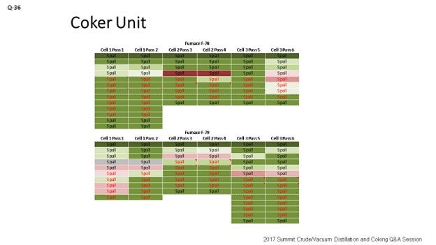
What can you do to optimize the spall approach? We came up with a chart, which you can see on the slide. The chart uses colors to measure performance. What do the colors tell us? Well, green means go; red means stop. The more green you see, the more delta T is being minimized and getting closer to zero. Red on the chart indicates that the spall did not go well. The point I want to make is that when a spall does not go well, you want to get with Planning right away and try to schedule another spall in that same pass as soon as you can. Because if you do not go after that pass right away, you may end up in a pigging situation. Like I said, green means it is directionally where we want to go. You can see there are different colors on the fonts, too. As we change the type of spall, we change the color of the font we use to represent the different spall durations utilized for the spall. So, the green and the red are the measures of the true effectiveness of the spall.
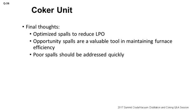
Some final thoughts: Optimized spalls are obviously going to help reduce lost profit opportunity; because when the efficient spalls are planned properly, they will be effective in getting the furnace performance back where it needs to be. Opportunity spalls are something that a refiner should really have in the forefront when looking at coker operations. ‘Opportunity spalls’ are the term we came up with when an opportunity essentially presents itself. For instance, you have some other upset in your refinery that has slowed down your coker. You have room on the coker rate, so you can go after a free spall essentially as long as you have the steam available to do that. Get your heater performance back up on track so that when you are able to push the coker again, you will not have to worry about that spall that was scheduled a week or two out.
I will tell you that the opportunity spall is something which needs to be ingrained in your culture; because as I have seen changes in the Operations team over time, they have lost sight of that opportunity. As a result, we have gone through an LPO (Lost Profit Opportunity) situation where we have had to cut back on crude runs only to come out and start the coker rates up again. And then within a week after raising coker rates, we had to slow down crude and coker rates again to spall. So, obviously, you want to try to avoid that type of coker slowdown. The last point is that the poor spalls really need to be addressed quickly. If you are not effective with a spall, you run the risk of going into a pig and having a shutdown.
LOGEROT (Prosys Inc.)
You have heard the first two guys talk about trying to develop what might be considered an optimum procedure for the spalling. Héctor spent a lot of time on the four gates. So, I am going to introduce the concept from process control. Once you have decided on your optimum procedure, how will you be sure that you will follow that optimal procedure every time? There is a mechanism that, in the process control world, we call ‘procedure automation’. You can leverage your automation tools. They will allow you to automate your spalling procedure. So, ultimately, you get to a point where the operator just presses a button and says, “Spall this pass,” and the control system goes back doing all the spalling.
Now what I heard these guys say, too, is that some of the steps are rigid and that you want it to be on exactly this flow rate for this time and that temperature. Some of them are more flexible. You can build the flexibility into your procedure automation system by allowing the operator ranges of set points or controls for a particular part or step of the operation. So, basically, if you can write down your procedures in a stepwise fashion and provide the operating conditions that you want in each step, then it can be automated. When you automate it, you basically ensure that your “Best Operator” is on board all the time. Your “Best Operator” is really that control system which is controlling it and telling you exactly which steps you want and in what order, as well as which control settings to use each time.
ROGER METZLER (Baker Hughes, a GE Company)
When you are performing repetitive spalls, do you see a point at which you begin consistently getting diminishing returns and you just know you are only going to be able to perform so many spalls before you will have to set up a pigging or a decoke?
GAMBOA-ARIZPE (CITGO Refining & Chemicals, L.P.)
After several decoking operations, the refiner gets to the point where the spalls are no longer as effective. Usually, the convection section of the coker furnace becomes limiting because the spall is not as effective at cleaning the convection section. So, over the course of three or four spalls, you may have to come back and do either a steam/air decoke or a pigging operation to restore the performance of the convection section. Fortunately, the convection section does not foul as severely. It fouls a bit slower. But because of the general inability to get the right temperatures in the convection section tubes during spalls, the spalls are not as effective in that section.
One of the other points I want to make is that if you do have a spalled pass that did not perform as well post-spall – say you have a heater with four passes and one of them did not do so well – and if you do not do what Eric said and go at it again and reestablish a better spall, then you will end up with an imbalance on the heater. That imbalance is what will drive the heater to foul up more severely during the next run.
TARIQ MALIK (CITGO Petroleum Corporation)
I heard various times for the online spall. Darwin had it at 16 to 24 hours, and I think Eric said 24 to 36 hours?
LÉGARÉ (Andeavor Martinez Refinery)
Forty-eight.
TARIQ MALIK (CITGO Petroleum Corporation)
Forty-eight. So, what tells you that you are done? I would like to be done in 16 hours, but I can never complete a spall in 16 hours.
LÉGARÉ (Andeavor Martinez Refinery)
The range I gave will be in the Answer Book section of the transcript. We were basing it on a 48-hour spall because that was what we needed to get the performance we targeted. What happened was that we did not have the right information from our Inspection Department. As far as the temperature limits, we could see limits on the heater and the outlet piping temperatures. So, once we established a higher allowable outlet temperature on the furnace outlet piping, we were able to spall at a higher temperature and get the performance we needed in 24 hours instead of 48.
TARIQ MALIK (CITGO Petroleum Corporation)
May I ask at what temperature?
LÉGARÉ (Andeavor Martinez Refinery)
The revised temperature was 1300°F.
TARIQ MALIK (CITGO Petroleum Corporation)
For the next question, I want to poll the panel. At what tube-metal temperatures do you trigger the decoke, spall, or pigging of the heater? Do you go to 1300, 1400, or 1275°F? What is that number you reach where you say, “This is the limiting temperature; now decoke the heater tube”?
GAMBOA-ARIZPE (CITGO Refining & Chemicals, L.P.)
I think ours is between 1300°F and 1350°F.
TARIQ MALIK (CITGO Petroleum Corporation)
Is that 9-chrome tubes or stainless?
LÉGARÉ (Andeavor Martinez Refinery)
We are in the same range of 1300°F.
TARIQ MALIK (CITGO Petroleum Corporation)
Thirteen hundred? I do have one more question for Jeremy on that heater that does 12°F fouling a day.
THEISS (Marathon Petroleum Corporation)
I said 6 to 12°F.
TARIQ MALIK (CITGO Petroleum Corporation)
Okay: 6 to 12°F. I just took the upper number. You said that there are three cells. How many passes per cell?
THEISS (Marathon Petroleum Corporation)
Two.
TARIQ MALIK (CITGO Petroleum Corporation)
Okay. Thank you.
ERIC LÉGARÉ (Andeavor Martinez Refinery)
Delayed coker furnace spalls are performed to remove the buildup of coke on the inner walls of the furnace tubes in order to improve furnace heat transfer and maintain unit throughput and efficiency. As furnace spalls require coker and sometimes refinery crude rate reductions, they should be planned and communicated effectively to the refinery’s Planning Department to ensure that crude and product inventories are managed appropriately. Effectiveness of the spall cannot be measured during the spall, so it is only after completion of the spall that effectiveness can be determined. The Coker Operations Team will manage the spalling procedure and communicate spalling results for each planned spall. Spall effectiveness should be captured as part of the unit’s health monitoring report and tracked on an ongoing basis.
Spall effectiveness is monitored by the process engineer – after the spall is complete – by comparing the furnace tube skins’ start-of-run (SOR) temperature after the spall with a post-pigging or post-turnaround SOR furnace tube skin temperature. If post-spall SOR temperatures do not meet expectations, the details of the last spall should be investigated as changes may be required to the spall procedure and/or duration and will need to be communicated to Planning. A poor spall can introduce an unplanned event in the refinery’s monthly plan to recover coker furnace performance before the coke may prove too difficult to remove in a spall and pigging becomes the only solution. Note that the Coker Operations Team should always be looking for a window for an “opportunity” spall to regain heater performance when little or no refinery impact would be incurred.
Spall efficiency is optimized by maximizing spall temperature, which is measured as the furnace pass outlet temperature. Work with your Inspection Department to determine the true limits of your furnace tubes and/or furnace outlet piping. One Andeavor site worked with a lower furnace outlet limit for a couple of years. This resulted in longer spalling durations as effectiveness was impacted by the temperature limitations. The Inspection Department reviewed the piping metallurgy and provided relief on the historical spalling temperature limits.
Quantity and quality of velocity steam (high pressure, dry) is important when determining the optimal spall conditions. Determining the type of spall technique – shock spall or continuous spall – will also affect the efficiency of the spall. Shock spalls will utilize a cycling of spall temperatures to try to break off the coke using a mix of hotter and cooler temperatures in the tube passes. Continuous spalls will use constant temperature and velocity steam to help spall the coke off the tubes.
Spall duration can be seen as a tradeoff between the number and duration of spalls per year. If your spalling effectiveness is not meeting the expectations of your Refinery Leadership Team, it is recommended that a plan be developed using a test matrix to determine the most effective spall method for your unit. Higher spall temperatures within established limits and longer spall durations are preferred, but optimization to minimize durations will always be requested by your Planning Department.
Below is an example of a test matrix which can be used to develop an optimized spalling technique. An Andeavor site created a table that utilized conditional formatting to compare spall effectiveness and spall technique to generate a visual tool to demonstrate overall spall effectiveness. Darker green means spall effectiveness closer to baseline, with dark reds indicating a poor spall. Font color is used to explain the duration of each specific spall. Parameters that were changed included duration and furnace outlet temperature. Changes led to a new spall procedure that takes 24 hours to achieve the same performance that spalls of 48 hours did a year ago. This modification reduces the LPO associated with planned spalls by up to half.
Year
2017
Process
Question 35: What are your major parameters and mechanisms that affect coker furnace fouling? Are there known effects from some specific crude properties? What are typical fouling rates, and how can they be minimized?
SOLOMON (Athlon Solutions)
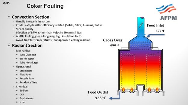
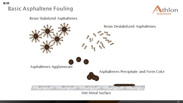
Favorable coker margins have caused all refiners to take a good look at the coker furnace fouling and how we can extend our run lives and get more out of them. Two areas obviously within the furnace – the convection section and the radiant section. Look at two different ways of what is going on to understand what parameters and mechanisms are causing fouling. In the convection center, we are mainly looking at organic solids – obviously, the crude slate – to understand how the crude is behaving, identify the properties, and also look at steam quality. Then of course, down in the radiant section, we are looking more around operational issues. How are we managing the operation of fluid rates and steam rate, and in total, the bulk fluid rate? Mechanical; What tube diameter and metallurgy can be used? It is also important, as are the chemicals being used, to understand contaminants in the fluid such as sodium, asphaltenes, or iron. Understand the exact details of the crude slate.
Feed factors that obviously affect fouling are the asphaltene content, which is the biggest factor we were seeing, and understanding the stability of the asphaltenes. Understanding the types of inorganic solids is critical. There are various sources of inorganic solids – including corrosion byproducts, salts, and caustic injection – that we put into the crude, and various materials – clay and dirt – that are coming out of the formation, as well as all of the transportation issues. The main process for fouling is really destabilization of asphaltenes, whether caused by changes in pressure or the high cracking temperatures that exist in the furnace.
What we see is that the asphaltenes tend to be stabilized by resins and aromatics. When you get to high coking temperatures, those resins and aromatics start to crack and can form large-chain molecules that eventually reach the solubility limit; then, agglomeration and deposition starts to happen on the tube surface. The asphaltenes are also less stable in the absences of these resins and aromatics, and they start to deposit on the tube surface as well.
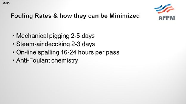
How do you minimize fouling and manage to remove some of the fouling that has occurred? There are various methods. Mechanical pigging can be done every two to five days. Steam-air decoking can be done at about the same duration: two to three days. Online spalling tends to be one of the favorites as it is being done 16 to 24 hours per pass. Then of course, well, being the chemical guy, anti-fouling chemistries have started to really show some differences in the ability to manage fouling and mitigate it.
THEISS (Marathon Petroleum Corporation)
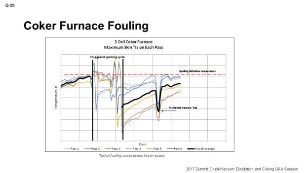
Kevin alluded to a lot of the mechanisms behind fouling. I am going to touch on a little of Marathon’s experience. We see big differences, obviously relative to crude slate. Kevin talked about that. At the refineries processing a lot of heavy Canadian, we can see fouling rates between 6°F and 12°F per day. We have seen double the fouling rates for those refineries processing heavy Canadian crudes. Really, tracking fouling performance is key to understanding not only when to go spall or pig or do whatever to decoke, but also to understanding how variable changes can affect fouling rates. So, if you want to mess around with the unit and see if it extends out your cycle, as far as the heater is concerned, understand that the data is really important.
The graph on the slide is an example of what we use at Marathon to track heater performance and determine when we need to spall our heaters. This specific example shows a staggered spall. It is a three-cell coker furnace, and the spalling cycle is somewhat staggered based on fouling rates on each individual cell.
I also want to touch on is some of the process variables you can alter to help affect coking. Obviously, we talked about crude selection. It could be very uneconomical to go down that path to select your crude based on your heater fouling rates, but it is an option. You just have to look at the big picture to be sure that is the right decision to make.
Thermal cracking can be minimized by increasing velocity and decreasing heat flux and outlet temperature. There are some penalties with decreasing outlet temperature as you will lose some yield. Obviously, it could also lead to some foaming events in the drums. If you have the equipment such as feed preheat, you will want to do your best to maximize feed preheat to minimize heat flux in your heater, which will help reduce some fouling. We have also done some testing with velocity steam and determined that going up to about 1.5% of velocity steam is really the peak amount of benefit you will get from increases in velocity steam. Too high velocity steam can increase your back pressure and actually reduce your heater tube velocity.
TARIQ MALIK (CITGO Petroleum Corporation)
Jeremy, you said that you had a heater with a fouling rate of 6 to 12°F per day. That is very aggressive. To what have you attributed that? You mentioned Canadian crude, but you cannot profitably operate a coker with a 12°F-a-day fouling rate. That means in about 21 days, you are done with the run-length.
THEISS (Marathon Petroleum Corporation)
Now we are doing it. It is not ideal, but primarily crude slate driven. It is a refinery that runs a lot of heavy Canadian crudes.
TARIQ MALIK (CITGO Petroleum Corporation)
Is that a double-fired or a single-fired heater?
THEISS (Marathon Petroleum Corporation)
Double.
TARIQ MALIK (CITGO Petroleum Corporation)
Double-fired heater and 12°F per day. That is not in the ballpark. What excess oxygen are you running on this?
THEISS (Marathon Petroleum Corporation)
I would say probably bouncing somewhere around 5 to 7%.
TARIQ MALIK (CITGO Petroleum Corporation)
That is good. Is it balanced or natural draft?
THEISS (Marathon Petroleum Corporation)
It is balanced.
TARIQ MALIK (CITGO Petroleum Corporation)
Okay. It is not adding up but thank you.
KOUSHIK GUMASTE (Baker Hughes Incorporated)
There is not a lot of literature available on the specific effect of sodium. Do you guys have any definitive proof that sodium does destabilize and cause more fouling? I have only heard it by word of mouth.
THEISS (Marathon Petroleum Corporation)
Actually, we recently had a little experience with testing caustic additions in our crude unit and determining the effects of translating that result to sodium fouling in the coker. With our testing that we did, it was really hard to tell the difference in coker fouling when we varied the level of caustic injection in the crude unit. That being said, there could have been other variables going on at that time. The bottom line is that we did not see a significant step-change in furnace fouling when we did some of those trials.
GAMBOA-ARIZPE (CITGO Refining & Chemicals, L.P.)
Just a secondary comment about the sodium: As Jeremy described, one of the other coker-related concerns with sodium addition, usually added upstream in the crude unit at the desalters, is the potential for the caustic embrittlement of the coker heater tubes, depending on your alloy. It is a problem that should not be ignored. The same embrittlement risk exists for the drums. The sodium starts leaching into the metal at a temperature as low as 800°F. Most of the delayed coking process occurs above that temperature, and so embrittlement risk is a concern that should not be ignored with sodium.
TARIQ MALIK (CITGO Petroleum Corporation)
Sodium is a well-known coke precursor, so coker feed should typically be less than 10 ppm (parts per million) sodium going in. If you have 20 to 25 ppm, you will impact run-length on the coker. Sodium is not good news in coker feed.
ALLEN KAISER (Delek Refining Ltd.)
I want to tell you two stories. First, we were blending a tank of caustic for our crude unit for injection downstream of the desalter. Due to some misalignments, we pumped straight 50 Baumé caustic into the desalted crude stream. When that hit the coker, we gained 100°F on the radiant TIs (temperature indicators) in a matter of about 12 hours. So, sodium, yes, has a big impact on TMTs (tube metal temperatures). As a result, we began paying attention to sodium a little closer; and then, we started – stepwise – bringing down the amount of caustic we were injecting into the crude unit.
Secondly, when we started measuring sodium, it was in the 50-ppm range. There was a big difference in fouling rate. The fouling rate was about three times higher than it had been in previous cycles. So, as we lowered that injection rate and got the sodium under 20 to 15 ppm, like Tariq was saying, yes, fouling rates started coming back down. Now, we are back to our more typical 0.5°F-a-day range. We got it back down in a more typical range.
HAROLD EGGERT (Athlon Solutions)
I think part of the confusion, if you are doing data analysis on sodium in the feedstock, is because no one has really delineated between sodium as sodium chloride and sodium as a function of overfeeding caustic. I think there is some debate as to whether it is the sodium or the sodium hydroxide. Most of the issues around the caustic are anecdotal. Like Allen said, we know we overfed caustic and that created an increase. But just looking at the lab analysis of the sodium in the coker charge may mislead you; the convention being that sodium chloride is not as detrimental to furnace fouling as overfeed of sodium hydroxide.
WARREN LETSZCH (TechnipFMC)
I have a question for the panel. If you are building a new coker today, how will you design the unit to do the decoking? Would you do steam/air decoking? Would you do it with pigs? What would you put in for a brand-new unit?
LÉGARÉ (Andeavor Martinez Refinery)
I will respond since I have one of the newest cokers out there. They are all designed for online spalling.
LÉGARÉ (Andeavor Martinez Refinery)
Oh, Yes. Definitely.
ROBERTSON (AFPM)
And that is the next question.
GAMBOA-ARIZPE (CITGO Refining & Chemicals, L.P.)
Yes, we will address that topic in the next question. We would not let you down, Warren.
KEVIN SOLOMON (Athlon Solutions)
The major factors affecting coker furnace fouling fall onto three key areas: mechanical, operations, and feed.
Mechanical: Configuration and design elements of the furnace that have significant impact to fouling are:
-
Tube diameter, which affects residence time and pressure drop.
-
Burner type, which affects flame impingement and issues arising from dirty fuel gas; and,
-
Tube metallurgy and surface roughness: 9 Cr, 12 Cr, 316 to 317L. Different metallurgy have different max skin temperatures. Some can be 150°F higher, which allows for longer run lengths between coking.
Operational: Deviation from industry published operating parameters can cause or exacerbate fouling. The following guidelines should be followed:
-
Maintain flow rate (cold liquid): 6 to 8 fps, which is the hydrocarbon flow rate before adding steam.
-
Bulk fluid rate: 10 to 12 fps; includes oil and steam.
-
Operating temperatures: less than 750°F.
Feed: There are several specific issues related to the feed material that affect fouling. Factors found in the coker furnace feed that can cause or exacerbate fouling are:
-
Sodium levels in the crude.
-
Heptane insoluble-to-carbon residue ratio.
-
Asphaltenes content in the crude.
-
Understanding of the metals type and concentration.
-
Understanding the stability of asphaltene, with respect to the crude slate, can help predict fouling and permit actions to be taken to reduce fouling rates.
-
Inorganic solids, such as corrosion by products, filterable solids and salts, and sodium can come from a variety of sources.
-
Corrosion byproducts can originate from upstream operations such oil production, transportation, crude oil storage, slop products, and contamination in the velocity steam or boiler feed water.
-
Salts can be from the salt water in the oil producing formation and brine contamination occurring during transportation.
-
Caustic may result from injection into the crude to reduce overhead chlorides.
-
Clay, dirt, and catalyst fines may be introduced from upstream production activities, transportation, and refinery processes upstream of the coker furnace.
We have already discussed that asphaltene destabilization – and thus, precipitation – is a leading cause of fouling. Destabilization can occur because of several factors, such as changes in press, temperature (greater than 750°F), and acidity. Free-radical polymerization is the process by which we believe fouling occurs. During this process, aromatics and resins are cracked. The asphaltenes react to form longer chains; and once solubility is exceeded, deposition and agglomeration occurs on the surface of the tubes.
Fouling rates vary depending on the crude slate, feed rate, feed properties, operating conditions, and the condition of the coker furnace. However, there are several ways we can minimize the impacts of fouling. Some are physical, and others are crude management and chemical treatment.
Mechanical pigging steam-air decoking and online spalling are activities that can help remove fouling buildup, to a certain extent. During any of these operations, feed throughput is reduced.
Crude management is focused on understand asphaltene stability and ensuring that the crude slate is as compatible as possible to prevent issues. Analyzing crude slate and determining asphaltene stability can give us an indication of potential fouling issues.
Utilizing a proven coker furnace antifoulant injected ahead of the furnace can help to reduce the rate of fouling without the need to reduce feed rate.
JEREMY THEISS (Marathon Petroleum Corporation)
Causes of Coker Furnace Fouling
Quality of feed is the major parameter in coker furnace fouling. MPC coker heater fouling rates have increased significantly over the past ten years, especially on coker units that process heavy Canadian crudes. We attribute the fouling increase to higher volume percentages of asphaltenes associated with the heavier crude slate. Heavy Canadian crudes can contain solids from the mining operations and diluent used to process these crudes, both of which can destabilize the asphaltenes and result in high heater fouling rates.
Other contaminants such as inorganics can also increase coker furnace fouling. Inorganics tend to precipitate in the convection section, where it is difficult to remove with online spalls. Inorganics, such as sodium, are introduced with incoming crude or injected during crude processing to manage overhead corrosion. It is recommended to manage sodium content below 20 ppm in coker feed.
Finally, the classic fouling mechanism for a coker furnace is thermal cracking. Coke from thermal cracking normally accumulates in the lower radiant section of the heater. Typical heater coking rate due to thermal cracking is around 1 to 4ºF/day depending on the asphaltene level in the feed.
Fouling Rates
One of our coker’s heater fouling rates more than doubled in the past five years with an increase in heavy Canadian crude throughput. This specific heater used to conduct decoking every six months and now goes through decoking every two months. Most refineries in the mid-west that process heavy Canadian crudes experience heater fouling rates between 6 to 12ºF/day. Our mid-west refineries that have similarly designed coker heaters to our gulf coast refineries can experience double the fouling rates.
Within MPC, coker heaters that spall online evaluate a shutdown every two to three years to pig the heater and hydro-blast the transfer line. We normally see heavy accumulation in the convection section and transfer line during the cleaning. Fouling of the transfer line increases back pressure which suppresses vaporization and increases residence time in the furnace. After three years, we have seen a 50-psi increase in furnace inlet pressure due to transfer line fouling. We normally see run-length increase by as much as 50% after cleaning the transfer line/convection section.
Reducing Fouling Rates
If a crude selection change is not an option or economical, there are some changes that could directionally assist with heater fouling. Thermal cracking can be minimized by increasing velocity, decreasing heat flux, and decreasing coil outlet temperature. Heat flux is a function of heater design, heater charge rate, and heater inlet and outlet temperatures. Assuming that the heater is properly designed, and the burners are evenly distributed, the operator can reduce heat flux by maximizing feed preheat and optimizing heater outlet temperature. We normally set heater outlet temperature to target coke volatile carbon matter (VCM) around 10 wt% (weight percent) and meet coke hardness specifications. Although, managing heater fouling by lowering heater outlet temperature can result in more hot drums and foaming events. We normally set an upper limit of 12 wt% on VCM to prevent drum operational issues. Running lower heater outlet temperature will result in a yield penalty, which must be considered.
We have completed several tests on the effects of velocity steam. These tests show an increase in velocity steam rate helps to a point but does not provide much gain in heater run length when velocity steam is above 1.5 wt% of the feed. We think higher velocity steam rates can increase back pressure to the furnace, which in effect reduces the velocity in the furnace.
CHRIS CLAESEN (NALCO Champion)
The furnace firing and design has a big impact and needs to be studied and understood before other parameters are investigated. Feed properties, such as solids and metals content and stability, will impact the coking rates and can be controlled by proper blending and removal of solids/metals at the desalter. Antifoulants can further help reduce the coking rates due asphaltene instability.
GREG SAVAGE (NALCO Champion)
The coker furnaces are often a limiting factor to unit and refinery throughput. One factor limiting charge to the furnaces is spalling, steam-air decoking, or pigging, which is triggered when any tube in a pass reaches the maximum tube metal temperature (TMT) for the given metallurgy. The increase in TMT can range from 0.1 to upward of 10°F per day, depending on the fouling rate and furnace operation. Primary causes of coker furnace fouling are poor tube cleaning, overfired tubes, local high heat fluxes due to fuel or burner issues, inadequate mass velocity, high heat flux, and high fluid bulk temperature, as well as high levels of metals and solids in the bulk fluid. Poorly cleaned tubes can leave deposits and rough surfaces, which can serve as sites for fouling initiation during operation. Burner tip plugging due to solids and liquids in the fuel can cause poor distribution between the ports or port enlargement (as a result of erosion or oxidation), which can lead to high burner tip pressure, flame impingement, too few burners, uneven heat release, and fireside tube fouling from products of incomplete combustion and ash. These burner tip issues can cause localized hot spots that can promote the formation of coke deposits. Inadequate mass velocity leads to increased residence time and film temperature, as well as reduced turbulence. In low velocity regions, asphaltenes are more readily removed from the bulk fluid and are more likely to form coke. Low fluid velocity is a major contributor to furnace tube coking. High heat flux due to overfiring can be caused by poorly tuned instruments, fuel composition change, excessive throughput, high exit temperatures, or poor operational control. High heat flux raises the fluid film temperature and increases the coking reaction rate. High exit temperatures increase the fluid bulk temperature and therefore increase the potential for coke formation and deposition. Salts, dirt, caustic, and other contaminants in the fluid can catalyze asphaltene formation, increase coking tendency, and adhere to deposits.
Tube-side fouling deposits are typically a combination of corrosion and fluid decomposition products, as well as salts or dirt. These solids can adhere to the tube walls forming deposits, which interfere with the heat transfer and increase localized temperatures. These products are formed from a complex reaction dependent on the temperature of the wall film and the time of exposure to that temperature, i.e., wall film thickness (related to fluid velocity). Consequently, the heat flux and the mass velocity heavily influence the rate of fouling. Coking reduces potential unit run lengths because it increases heater tube temperatures to near metallurgical limits and also increases pressure drop in the heater, causing hydraulic limitations. Reducing the frequency of coking incidents and the rate of coke formation is thus important to increasing plant utilization.
Coker heater fouling is promoted by thermal destabilization and precipitation of asphaltenes followed by dehydrogenation of the deposited species at the furnace tube temperatures to form coke. Asphaltenes are kept suspended in the feed through resins that are attached to the particles. As the feed is heated, the resins increase in solubility and detach from the asphaltene particles, which causes the asphaltenes to precipitate. The asphaltene particles then lay down on hot surfaces and form coke deposits. The formation of asphaltene precipitate and degradation to coke can be catalyzed by iron, sodium, and vanadium. Tube wall roughness from corrosion, fabrication, poor mechanical cleaning, or deposition of asphaltene particles can act as a coking initiator.
The furnace exit temperature controls the flow of fuel and the distribution of feed to the passes and can be adjusted to increase cracking and improve yields. Consequently, proper control of the exit temperature and instrument tuning is important to optimizing unit profitability while minimizing the fouling risk. Burner tips that are frequently taken out of service increase the risk for formation of localized coke deposits. During spalls, burners can be taken offline to reduce the heat flux. Removing burners rather than controlling the fuel gas flow during a spall can lead to localized hot spots and formation of coke deposits.
Hot air can increase combustion efficiency, but it has also warped air distribution equipment at some refineries, which has caused some uneven heat flux distribution, and contributed to fouling. Some refiners lack sufficient O2 sensors in the firebox in each pass. At least three O2 sensors are recommended to ensure proper combustion and distribution. Excess O2 is controlled, depending on coker margins, and some refiners have found that higher excess O2 reduced spall rates. Additionally, CO meters can indicate incomplete combustion and the need for additional O2. Air and fuel gas distribution issues can result in the firebox ends being consistently colder than at the center, which increases the risk for the formation of localized coke deposits. Also, sagging in tubes – due to loss of mechanical support – can change flows and heat distribution, leading to hot spot development.
Cleaning of the furnace convection section can be done with dry ice. However, limited mobility and access can restrict the amount of surface that can be reached. Despite the limitations, recoveries of over 100°F have been found by refiners. External fouling of the convection section results in elevated heat flux in the radiant section, which increases the formation of coke deposits. Poorly cleaned tube internals can leave deposits and rough surfaces, which can serve as sites for fouling initiation during operation. After cleaning a tube, the temperature should consistently recover; otherwise, the cleaning may not have been effective.
The total heat flux is calculated using the fuel gas rate, fuel energy content, and tube surface area. Usually, the heat flux in the radiant section is 70 to 80% of the total heat flux and should be compared to the design maximum. Mass velocity is calculated using the cross-sectional area of the tubes, the mass flow rate, and the steam injection rate. Generally, the recommended mass velocity is between 350 to 450 lb/ft2-sec (pound per square foot per second). Steam is often injected for safety reasons, to change partial pressures, and to increase the velocity through the heater. A general guideline for steam injection is 2% by weight.
Coker heater tube fouling rate can be controlled through firing rate, velocity steam, and specialty chemicals. The most effective method of controlling heater tube fouling is increasing mass velocity, followed by reducing heat flux. Blending of slurry oil, increased recycle, or even light coker gasoil into the feed have each been effective at reducing furnace fouling rates, but generally with economic penalties. Laboratory simulation of blending these components into the coker feed can indicate the estimated benefit for a full economic evaluation of these options.
When process parameters are within the recommended envelope and other blend streams are not economical, proper injection of chemicals can help reduce the fouling rate. The coker heater protection program implemented by NALCO Champion uses a combination of passivation, dispersion, and coke suppressant chemistries to reduce the fouling rate. A phosphate-based filmer passivates metal surfaces, reducing activity, thereby inhibiting the metal surface’s ability to catalyze the formation of coke from asphaltene particles. An asphaltene dispersant stabilizes the resins that keep the asphaltene particles dispersed and therefore reduces the potential for deposition. Inorganic dispersant chemistry reacts with reactive sites carried in the coker feed, which initiate the formation of coke deposits.
Year
2017
Process