
Question 4: The economic benefit for propylene and amylene alkylation is improving. What considerations do you use in the feed pretreatment and alkylation unit operations before increasing these feeds?
CHRIS STEVES (Norton Engineering)
Increased processing of propylene and amylene feedstocks in alkylation (alky) units does bring challenges, but most will depend on the configuration of the existing unit and whether any of these feedstocks have been processed before.
Modification of a butylene-only alkylation unit to handle larger volumes of propylene may involve significant capital modifications to add or expand the capacity of C3 handling equipment. Examples include the depropanizer, C3 defluorinations (in HFalky units), and refrigeration equipment (for sulfuric acid alky units). With sulfuric acid alky plants, consideration will also be required for treating the reactor hydrocarbon stream before fractionation. Caustic treating systems may require the caustic circulation rate to increase by as much as twice the butylene-only rate to treat and remove esters from the reactor effluent of a propylene alky unit. In addition, the temperature required to break down these esters in the caustic treater will need to increase, potentially as much as 40°F above current operating temperatures, due to the higher stability of esters in the reactor effluent of a propylene alky unit.
In sulfuric acid alkylation units, separate reactors for propylene-rich and butylene-rich streams can help in managing acid consumption, as the different feedstocks respond differently with regard to acid consumption at different acid strengths and operating temperatures. A strategy of processing a propylene-rich stream in the high strength reactor and the butylene-rich stream in the low acid strength contactor can help to minimize overall unit acid consumption.
In addition to alkylation unit modifications for propylene alkylation, the alky feed treating will need to be reviewed to ensure that the sulfur is adequately handled and that C2is properly stripped from the alky feed stream. For addition of propylene feed, removal of H2S (hydrogen sulfide) with amine and/or expansion of the caustic pre-wash equipment should be considered so as to not negatively impact the operation of the mercaptan removal system with the production of non-regenerable sodium sulfide.
Addition of amylene to alky feed may also typically require modifications to the alky unit equipment. The extent of the modifications will depend on the desired level of amylene. Some considerations include the following:
In sulfuric acid alkylation units, amylene alkylation can be safely practiced at lower acid strengths than with propylene or butylene alkylation. With a separate reactor for amylene processing, the overall acid consumption on the unit can be minimized by allowing the final spending strength to fall lower than what would be practiced with butylene alkylation.
In sulfuric acid units, amylene alkylation is more sensitive to temperature than butylene alkylation; but with limited propane in a separate amylene reactor, the desired lower temperature may be difficult to achieve. Modifications to the refrigeration system may be required to optimize the individual reactor sections with regard to operating temperature.
In both sulfuric acid and HF alkylation, introduction of amylene feeds will increase production of isopentane through hydrogen transfer reactions (although at higher rates in HF alkylation). Removal of isopentane from alkylate may require fractionation changes in the alky unit. The isopentane production can be minimized through recycling of isopentane from the fractionation section back into the reaction zone, but this process would require additional fractionation equipment.
Amylene alkylation will also require a review of the alky feed treating system. Introduction of heavier feedstocks to the mercaptan treating section may impact the overall sulfur of the alky feed (which will then impact acid consumption), as the heavier mercaptans are more difficult to extract. Introduction of heavier feedstocks to the alky feed can also bring undesirable species into the alky feed, such as cyclopentane and diolefins which consume acid at a significant rate. While cyclopentane can usually be excluded from the alky feed via upstream fractionation, treatment of diolefins may require separate reaction systems to remove them from alky unit feed.
KURT DETRICK (Honeywell UOP)
The issues in an HFAlkylation unit are different for propylene and amylenes.
For Propylene:
The types of contaminants and the concentrations of those contaminants that must be removed in the feed pretreatment section is not much different from butylene. The one difference is that there can be some ethane and ethylene that comes in with the propylene feed. Ethane tends to act as a Non condensable and requires venting from the depolarizer overhead system, which will cause increased acid losses. Ethylene does not react with iC4 in the HF alky unit but tends to make ethyl fluoride, which will cause higher organic fluoride content in the untreated propane and resulting in higher alumina consumption in the propane defluorinations.
The operational issues with propylene are primarily increased consumption of isobutane and propane rejection. The increased isobutane consumption is due to the fact that about 20% of the propylene will undergo a hydrogen transfer reaction where one molecule of propylene will react with two molecules of isobutane to produce one molecule of propane and one molecule of isooctane (C8 alkylate). This reaction actually helps improve the alkylate octane, but it causes a somewhat higher consumption of isobutane than might otherwise be expected.
The propane rejection issue is often the controlling factor in how much propylene feed can be handled in each particular unit. There is a limit to how much propane the fractionation and stripping columns can handle, and that limit is dependent on the specific unit design. One problem that can occur as the amount of propane coming though the unit increases is that the concentration of propane in the main fractionator or isostripper overhead vapor increases, causing a decrease in the condensation temperature, and this temperature reduction can “pinch out” the overhead condenser, thus limiting the available cooling duty of this exchanger.
For Amylenes:
The types of contaminants present in the amylenes are a little different from the propylene and butylene feed. Also, the concentration of contaminants such as sulfur and diolefins is higher. These changes can require adjustment of the operation–or even the design –of the feed pretreatment units. For example, the heavier mercaptans that co-boil with amylenes have a lower solubility in caustic, and they tend to be present in higher concentrations; therefore, a higher caustic circulation rate may be required for the mercaptan extraction unit in the feed pretreatment section.
Amylenes can also undergo a hydrogen transfer reaction in which one molecule of amylene will react with two molecules of isobutane to produce one molecule of isopentane and one molecule of isooctane (C8 alkylate). As with the propylene hydrogen transfer reaction, the amylene hydrogen transfer reaction actually helps improve the alkylate octane; however, it causes a somewhat higher consumption of isobutane. The amount of amylene that undergoes this hydrogen transfer reaction depends on several factors and can be anywhere between 30% and 60%.
The isopentane that results from feeding amylenes (both in the amylene feed itself and that which is produced by the hydrogen transfer reaction) can cause the alkylate to have a somewhat higher Reid Vapor Pressure (RVP). It may be necessary to draw some of the isopentane out with the n-butane product if a relatively low RVP alkylate product is desired.
For Both Propylene and Amylenes:
The octane number –both RON and MON (motor octane number)–of the C7 and C9 alkylate that is produced is about 5 to 10 numbers lower than the RON and MON of C8 alkylate. So, higher concentrations of propylene or amylene in the feed will decrease the alkylate octane if all other variables are held constant. Of course, if the addition of propylene or amylene to the feed results in more total olefin in the feed to the unit, the isobutane-to-olefin ratio may decrease, which will cause lower alkylate octane and higher ASO production.
Year
2016
Process
Question 86: What test method (e.g., ASTM D86, D1160, or D2887) do you currently use to determine the distillation of FCC gasolines, cycle oils, and fractionator bottoms?
AVERY (Albemarle Corporation)
I put distillation methods into two different categories. One is simple distillation or acts of distillation, which is either a D86 or D1160. D86 is at atmospheric conditions; the D1160 would be at a vacuum. More people are switching to simulated distillations or using a GC (gas chromatography) to do that. The most common number is a D2887. There are other numbers, depending on if there is oxygen in the stream, if you want light ends, or if you are really focusing on heavy ends.
The GC methods are becoming more common because they require a smaller sample size and because an operator can do far more methods that way. As an example, in our laboratories, we used the D1160s but have now switched to D2887 for most types of streams. We also use high temperature simulated distillation for some heavy resid types. We could run about 12 in a day if we did a D1160. Since we switched to simulated distillation with GC methods, one operator can do a hundred samples in a day by himself. So, we saved quite a bit a time when we switched to using GC methods.
I took a survey of over 60 FCC units worldwide. The slide shows a list of the naphtha streams, LCO streams, and slurry in feed. As you can see, D86 is more commonly used for the light boiling point ranges. This survey also ranged from 2000 to 2012. If I did a poll through that period of time, the ones close to 2000 used more of the simple distillations, like a D86, D1160; most common are all of the GC methods. More people are using what I listed as HTSD, which is high temperature simulated distillation. HTSD is a GC method that helps you measure the really heavy components that boil up to 1350°F.

I spoke with our R&D (Research & Development) guys and asked them to create a graph showing some examples of a D86, D1160, and simulated distillation. The yellow stream represents D1160 as the standard done in a vacuum. If you run a D86, you are going to see more thermal decomposition occurring above 650ºF. I forgot to mention that a D86 is generally not used for heavier boiling points; because somewhere around 600°F to 650°F, you will see thermal decomposition. You can see the D86 represented by the pink line. Once it gets into a higher temperature, about 700ºF, it will have a different slope due. When you start going to GC methods like the D2887, you will see larger tails. So, if you look at D1160 and at the simulated D2887, you will see a larger tail here in green and also a larger tail on the backend.

KEVIN PROOPS (Solomon Associates)
To the panel members in operating companies, as you have changed your distillation methods over time, have you gone back and updated all of your unit monitoring calculations to now calculate standard conversion at a 430 cutpoint using your new methods, or did you ignore the change in distillation method?
AVERY (Albemarle Corporation)
Data from refineries is often generated by using kinetic modeling. Within that process of collecting data, they will have inputs for the method. Those systems will automatically take care of the corrections.
BROOKS (BP Refining)
Our sites use models similar to those Cliff just mentioned.
SCHOEPE (Phillips 66)
I second that for Phillips 66.
AVERY (Albemarle Corporation)
Basically, distillation methods are in two categories: simple batch distillations (D86/D1160), and simulated distillations by gas chromatography. Initially refiners used ASTM D86 to determine oil boiling points (BP). The D86 simple batch distillation, or low efficiency distillation, is performed at atmospheric conditions. Decomposition or thermal cracking of the material can occur at temperatures greater than 650°F (344°C). Due to this high temperature decomposition, the ASTM D1160 method was developed. The D1160 is performed at reduced pressures [typically around 10 mm Hg (millimeters of mercury)]. At this pressure, oil fractions up to 1,000°F (538°C) can be accurately analyzed.
Simulated distillations (SimDists) are performed by GC. The most popular method is ASTM D2887. D2887 determines the boiling point distribution by injecting the oil sample into a GC that separates the hydrocarbons in a boiling point order. The retention time in the GC is related to the BP through a calibration curve. Recently, newer GC methods have been used. High temperature simulated distillation (HTSD) can accurately measure BPs greater than 1,000°F (538°C).
Simulated distillations save a significant amount of time, utilize less manpower, and require a smaller sample size: all advantages over simple distillations. At Albemarle, we run a standard D2887 for lighter BP fractions. For heavier oils such as FCC feed, we utilize a customized HTSD to assure we accurately measure the heaviest BP compounds. Our D1160 capacity was approximately twelve samples/day using one liter of oil and at least one technician. Our D2887 system has a capacity of 100 samples per day using less than one milliliter per sample and one technician.
Data from over sixty FCCUs were reviewed. The data runs from 2000 to 2012 and comes from every WW region. The general observation is that the method analyzed on feed is also performed for the slurry. For naphtha and LCO, many refiners are staying with the D86 method. More recent data and data from larger and/or major oil companies tend to utilize GC methods. Second-generation GC methods (HTSD) are showing up more often.
SCHOEPE (Phillips 66)
All Phillips 66 sites except one use simulated distillation methods for gasoline LCO and slurry distillation. D7096 is used for gasoline, D2887 is used for LCO, and high temperature D7169 or D6352 is used for slurry. One Phillips 66 site still uses D86 for gasoline and LCO.
Process

Question 9: What has been your experience with antimony and phosphorous poisoning on hydrotreating catalyst performance? What is the maximum level?
Kaspar Vogt (Albemarle) Antimony (Sb)
The effects of antimony in oil on hydrotreating catalyst have not been directly studied, but we can infer the likely impacts of antimony from a variety of information sources and past experiences.
As background, contaminant metals such as nickel can deposit on the FCC catalyst. This will result in increased dry gas (H2 in particular) and delta coke. Depending on the unit constraints this can lead to lower FCC conversion and lower feed rate. Many refiners use antimony in the FCC riser to passivate the detrimental effects of nickel. Antimony will cover the nickel enriched catalyst surface. Side effects are that the Sb will also cover the CO and NOx promoter metals and make these additives less effective.
Excess antimony mainly accumulates in the FCC slurry. However, antimony can be present in the heavier FCC products which are hydrotreated downstream. If the antimony enriched FCC catalyst fines are entrained into the hydrotreater, they can deposit in the catalyst interstices. This will impact bed pressure drop but not catalyst activity. The bed pressure drop build up can be managed by a guard bed catalyst system of sized and shaped catalysts to increase the void fraction and create more particulates capacity.
By analogy with the FCC experience, we would expect antimony in oil to preferentially coat nickel and cobalt promoter metals on the NiMo and CoMo catalysts. Ultimately, this would completely poison the catalyst. During the buildup of coating/poisoning, the activity will likely see a shift towards direct desulfurization (DDS) vs. indirect/aromatic saturation, thus the hydrogenation-to-hydrogenolysis ratio will change. A given concentration of Sb on catalyst would be expected to have a more severe effect on the catalyst performance in high severity HDS/HDN operations like ULSD and hydrocracker pretreat (HC-PT) service than in lower severity hydroprocessing applications such as NHT and LSD.
We seldom, if ever, detect antimony in the interior of spent hydrotreating catalysts where it would be expected to impact activity.
Furthermore, given its position in the periodic table, we would expect that Sb attacks the catalyst's active (NiMo and CoMo) sites, and that it would be a relatively severe poison, similar to arsenic (As), sodium (Na) and lead (Pb). Therefore, we would expect ≤1.0 wt% Sb would reduce HDN/HDS relative volumetric activity (RVA) by approximately 50% in non-severe applications, and that even lower Sb concentrations could severely reduce catalyst activity for high severity operations like ULSD and HC-PT.
Phosphorous (P)
Phosphorous (P) can come into the hydrotreater feed from:
- crudes
- drilling fluids
- phosphated ZSM
- phosphorous-based corrosion inhibitors and flow improvers
- phosphorous from solid phosphoric acid catalyst
-biofeeds
In catalyst manufacturing, phosphorous added on hydrotreating catalyst acts as a promoter and provides additional acidity to enhance HDN, hydrogenation and cracking reactions. Phosphorous also improves metals dispersion on the catalyst surface.
In one instance, we saw that 3 wt% of phosphorus on the catalyst terminated all the exotherm in bed, although other poisons where also present. Organic phosphorous can penetrate into catalyst pores. In general, our understanding is that the poisoning was similar to sodium where ~1.0 wt% concentration halves the catalyst activity.
In a separate instance, we found SiP coming from a solid phosphoric acid catalyst, used in certain FCC gasoline desulfurization processes with some iron deposited at the external surface of the catalyst extrudate. Some phosphorous and silicon also penetrated the catalyst pores. However after the first 0.1 mm, no contaminant phosphorous and silicon were found on a main bed CoMo catalyst. In this case, a layer of P-Si-Fe had deposited at the pore mouth and restricted the diffusion into the catalyst.
Photos of the outer surface including chemical composition are shown below. They show that Alumina, Molybdenum and Cobalt are homogeneously distributed within the catalyst particle, while phosphorous, silica and iron are located at the outer surface of the particle.
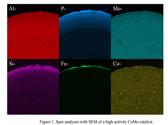
We observed that the Si & P from this process behaves totally differently from Si from anti-foaming agents. There are Si-P particles which cannot penetrate the internal pores of the catalyst and are deposited on the catalyst outer surface. The accumulation of these particles cannot be prevented. Therefore, sooner or later, bridges from particle to particle are formed, thus causing pressure drop buildup.
The bottom line is that the quantitative effects of phosphorous on hydroprocessing catalyst performance and the maximum allowable levels are highly dependent on the source and form of the phosphorous compound. It is also dependent on catalyst properties and the process application.
Martin Gonzalez (BP)
Phosphorus can sometimes be found in crude as alkyl phosphates added to passivate metals or protect against naphthenic acid corrosion. Phosphorus esters in crude may originate from waste oils, or from additives injected into wells to improve recovery. Some of the phosphorus may be in a form that volatilizes into distillate fractions bound for hydrotreaters. We have encountered some Canadian crudes containing phosphorus originating from fracturing fluids used in production. Phosphorus content in light sweet crudes seems to be declining, but it may be becoming more prominent in heavy crudes. There have been reports in the industry of ULSD units suffering catalyst deactivation as result of phosphorus from these crudes. From our experience, at 1 wt% on catalyst, it is reasonable to expect a 15-30% activity loss.
Charles Olsen (ART)
Phosphorous (P) contamination in oil has been traced to frac fluids that are often used in crudes from the Western Canadian Sedimentary Basin. The source is diphosphate esters which are soluble in the crude oil. Refineries that run large percentages of light Western Canadian crude have reported crude column and crude furnace fouling for many years. Improvements made to crude columns to minimize fouling have transitioned the depositing of phosphorous to the downstream hydrotreaters.
Other sources of phosphorous include gasoline slop tanks, imported feeds and lube oil wastes. If phosphorous does manage to make its way into the hydrotreater it will poison the active sites of the catalyst causing a loss in activity. A level of 1 wt% of phosphorous on the catalyst results in roughly 10°F loss in activity. ART recommends that a feed content of < 0.5 wppm be maintained whenever possible as well as the use of feed filters to assist in trapping of phosphorous sediment.
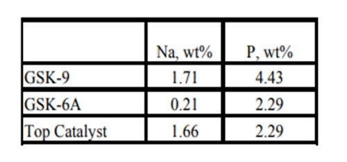
Historically, phosphorous contamination has not been very common, but with the increasing use of opportunity crudes it is being observed more frequently. A recent example is summarized in the table below shows the results of some spent catalyst analysis from a diesel unit. This unit experienced extremely rapid catalyst deactivation shortly after start up. It was so severe that within several months the unit required an unplanned turnaround and fresh catalyst was installed. The spent catalyst analysis indicates the catalysts were exposed to high levels of several poisons including sodium and phosphorous. The contaminants penetrated well into the catalyst bed. The level of contaminants indicates the catalyst in the top half of the bed had lost over 60°F of activity.
Year
2011
Process
Question 26: When you test for free HF and organic fluorides in alkylation unit products (alkylate, butane, propane), what are your typical observed levels? After HF breakthrough in our butane product, why does our treater still have plenty of KOH remaining? Is there any way to regenerate KOH during the run? Do others maintain a heel of KOH in the bottom of the alkylate storage tank to neutralize traces of HF?
Erik Myers (Valero)
These series of questions overlap quite a bit. The following answers address each question in the approximate order of those questions.
Our sites vary in the type of testing with most sites testing for combined (organic) fluorides in at least the propane and butane streams. Multiple stream points are typically tested dependent on what the monitoring goals are. Typical levels upstream of any treating are:
• Propane - 200 ppm
• Butane – 600 - 1000 ppm
• Alkylate – less than 100 ppm
Combined fluorides measured upstream of treating can be used as an indication of the completeness of the alkylation reaction. There will always be some level with the typical values noted above. Higher levels indicate potential issues with the upstream operation. The above values are for typical operations. Key contributors to increases in combined fluorides are low acid strength (below 85%), low reactor temperature (less than 80 o F), decreased contact time and low I:O ratio. Any of these can lead to increases in the amounts of all levels of combined fluorides. Propyl and butyl fluoride can increase by orders of magnitude with low acid strength. Post treatment levels of combined fluorides should be well under 10 ppm, typically.
Defluorinators are typically installed on the propane and butane streams, followed by KOH treating. These systems are occasionally used on the alkylate product stream. Water and HF are the products of the defluorination reaction. HF reacts with the defluorinator alumina to make aluminum fluoride trapped as part of the defluorinator alumina. This leads to potential of trace HF in the defluorinated stream if the remaining active alumina does not convert the HF. There is typically a lead – lag arrangement on the defluorinators to allow continued treating of the product streams. The downstream KOH treater is installed to dry the defluorinated product and remove any trace HF. It is less common to have a lead – lag for the KOH treaters but two of our sites have this arrangement on at least one stream. Some of our sites have water collection pots upstream of the KOH treaters to lessen the load of those treaters. To measure the effectiveness of the defluorinators and as an aide in determining optimum change out frequency, the streams are ideally measured before, between and after the treaters (with the downstream measured after KOH treating). The sample between the lead and lag defluorinators is used for confirmation of whether an alumina changeout is required. The upstream sample, along with the product flow rates can be used a predictive tool in scheduling lead defluorinator changeouts. The spent alumina can also be sampled and analyzed by the alumina supplier and compared to these predictive results for further alumina changeout optimization as well as verification of the hydrocarbon stream fluoride testing. One site uses a typical fluoride concentration and then a throughput totalizer to determine changeout timing, then analyzing the spent alumina to confirm loading.
Aside from the trace HF noted from the defluorination reaction free HF should not exist in the alky propane if the HF Stripper has adequate reflux and never show up in the normal butane or alkylate product. The primary cause for free HF is spent alumina in the defluorinators or severe loss of tower temperature profile in the alkylation fractionation tower(s). less than 1 ppm. Only one of our sites typically checks for free HF with the values being less than 5 ppm.
The KOH treater is typically a walnut bed downstream of the defluorinators. Our sites utilize both walnut and flake KOH, with walnut being typical. Our units are split with 50% have upflow and the other half downflow. This is typically an indication of the original unit licensor design. As noted earlier, water and HF are the products of the defluorinator. If the there is an HF breakthrough to the KOH treaters, it is most likely due to a spent defluorinator, where there is no more alumina to react with the HF. Significant breakthrough is important to avoid. Large amounts of free HF can cause the KOH treater to heat up resulting in hydrocarbon vaporization and unfavorable conditions for HF removal. (In a propane KOH treater, melting of the KOH and then freezing it in the outlet piping has actually been observed). One of our sites has an emergency alarm for high butane KOH treater outlet and delta temperature with another site having an SIS diversion for high C3 KOH treater temperature. The noted upstream and downstream sampling of each defluorinator is a key to staying on top of this processing area of the alky.
If KOH is still present in the treater while HF is measured in the product it is most likely caused by poor distribution through the KOH bed, either from channeling or crusting on the top of the KOH bed, sometimes caused by low amounts of water in the feed to the KOH treater. This low water content prevents the removal of KF (formed by the reaction of the KOH and the HF) from the KOH treater. Our sites have utilized either routine steam or water injection to the KOH treaters to prevent this.
Circulating KOH (typically used in the acid relief system neutralization system) can, and typically is, regenerated in a batch mode. We are not aware of a method to regenerate the solid fixed bed units as the KOH is converted to water and drained from the system. Three of our sites have two KOH treaters (either in parallel or series), allowing monitoring and changeout to be accomplished without compromising product quality. Residual KOH / water from the KOH treater changeouts can be utilized for make up in the circulating KOH system noted above.
Only two of our sites presently utilize a caustic heal in the alkylate product tank. This has been utilized at other sites in the past. This was done either as a preventative measure or as a result of previous issues with tank bottom corrosion. It is a common recommendation from the licensor. If this method is used, the tank water draw should be monitored frequently to measure changes and prevent loss of protection. The mechanism for tank bottom corrosion is either HF breakthrough from slumping of the fractionators, an exchanger leaks that routes acid to the tank or water in the alkylate product tank that leads to hydrolysis of the combined fluorides in the alkylate to HF if the residence time in the tank is long enough. The noted monitoring of any water draws and then ensuring that there is not water is another preventative measure for this.
Brad Palmer (ConocoPhillips)
Typical organic fluoride levels in alkylation unit products, upstream of any post-treatment, have been reported as 40-60 ppm (Alkylate), 200-400 ppm (Butane), and 300-600 ppm (Propane). Inorganic fluorides are not typically measured. Defluorination and KOH treating will reduce propane and butane organic fluorides to 10 ppm or less. Inorganic fluorides will be less than 1 ppm after treatment. Thermal defluorination, occurring in the heater passes, can further reduce organic fluorides in alkylate. Maintaining the fractionator bottom temperature above 320°F will thermally defluorinate any organic fluorides in the tower bottom thereby minimizing organic fluorides in the alkylate.
Un-used KOH material at breakthrough signifies bed channeling and/or a very dry system that allows KF to coat the KOH material. Defluorinator chemistry reacts organic fluorides with alumina to form alumina fluoride and water; an intermediate reaction product is HF, which may leave the defluorinator unreacted. The KOH treater is primarily a dehydrator and secondarily an HF neutralizer. As the KOH dries the LPG stream, the water "cleans" the KOH as it makes a sludge that is drained from the vessel. Any HF breakthrough from the defluorinator will react with the KOH to form KF and H2O. If there is very little organic fluoride to react in the defluorinator, there will not be much water formed to slough the KF off the KOH pellets. Some sites have used water injection to help "clean" and utilize the KOH material under dry conditions.
There is no effective way to regenerate solid KOH in the KOH treater with the vessel on-line. Water injection might be effective to refresh KOH that has been coated with KF as previously described.
It is a common practice to use an alkali heel in the alkylate storage tank. This is not for neutralizing HF, but is to counter-act iron fluoride scale leaving the process with alkylate which can form low pH hydrates on the tank bottom. The alkali heel should be tested routinely to ensure it remains basic.
Year
2011
Process

Question 16: What is the typical carbon monoxide (CO) concentration in the reformer net gas? How is the CO content measured? What are the potential effects to downstream units from the CO?
MELDRUM (Phillips 66)
Carbon monoxide can form in reformer units as the hydrocarbon reacts with moisture under very low-unit pressure conditions. Typically, semi-regeneration reformer net gas would have nil CO and only a minimal amount in a CCR-type unit. I expect it to probably be on the order of 5 ppm (parts per million), though some units report routine measurements of 10 to 20 ppm CO in their net hydrogen off gas.
One of our cyclic units that was operating at 400-pound had CO as high as 20 ppm in its net hydrogen stream when the recycled moisture rose to around 300 ppm. The excessive water entered the reformer from a leaking side reboiler on a wet debutanizer that used a slipstream of the reformer reactor effluent as the heat source. The water then returned to the reformer product separator. The high CO caused deactivation in the catalyst in a downstream isomerization unit.
Accurate measurements of CO in the net gas are difficult. Reformer units are not expected to have much CO, so they seldom have an online analyzer. A colorimetric tube – Gastec or Dräger type – can be used to give an indication of the presence of CO, but accuracy for a quantified number is difficult and requires the use of a carbon pre-tube to remove the hydrocarbons.
CO is detrimental to downstream hydrogen-using units in three principal areas. CO in hydrogen being fed to a distillate hydrotreater will methanate, consuming the hydrogen that would have otherwise been used for the desulfurization reactions. This will have the effect of lower catalyst activity. CO in hydrogen fed as a makeup stream to an isomerization unit will also methanate and form moisture that will deactivate the isomerization catalyst. CO that did not methanate in the second example could act as a poison to the platinum metal function of the isomerization catalyst. UOP suggests a CO limit of 1 ppm max for isomerization hydrogen makeup gas. My Answer Book response also includes some of the common steps used to minimize CO formation in reformer units, particularly in a CCR unit.
BULLEN (UOP LLC, A Honeywell Company)
As you can see in this table, we have correlated some different types of operation and ranges of CO levels. As Craig alluded, the numbers vary quite a bit, which can be due to conditions in the unit, as well as analytical capabilities. There seems to be a trend that the lower pressure units generate more CO than higher pressure units.

The laboratory method we recommend using is UOP 603, which is a laboratory method for CO and CO2 and hydrogen. However, a lot of refiners cannot do this method. The gas detection tube route is fairly common. Our point of view is that with the gas detection tubes, if one carbon pre-tube is good, then two is better. So, we usually ask them to use two tubes instead of one to help eliminate the breakthrough of hydrocarbons that can make a false high value for CO.
As Craig said, the issue with chloride and alumina isomerization catalyst is that you will deactivate the catalyst. However, if you are using another type of catalyst, like the Par-Isom catalyst or zeolitic catalyst, the actual suppression you will get will be very dependent on what temperatures you are running. As you approach the 400°F temperature, you tend to methanize the CO in the first part of the bed. So CO tends to have less of an effect on the metal function of the isomerization catalyst and becomes more of an issue of activity suppression due to the water on the acid sites. The same would apply if you had a saturation unit with platinum catalyst. It would also behave in a similar manner to these higher temperature isomerization units.
R.K. (RICK) GRUBB (Chevron Products Company)
Another aspect needs to be mentioned for the lower pressure reforming units. You have to take into consideration your nickel carbonyl formation when you shut down a hydroprocessing unit that is using the reformer hydrogen. You may have to either swap the hydrogen source or think of another shutdown procedure that will ensure no nickel carbonyl formation.
CRAIG MELDRUM (Phillips 66)
CO is detrimental to downstream hydrogen using units for three principal reasons:
1) CO will methanate in HDS (hydrodesulfurization) units consuming hydrogen, which will take away catalyst activity.
2) Much of the CO will methanate in isomerization units, forming water that will deactivate the isomerization unit catalyst.
3) The non-methanated CO in the isomerization unit will poison the metal function of platinum on the catalyst.
Note: The UOP suggested CO limit on isomerization unit hydrogen makeup gas is 1 ppm (10 ppm for CO + CO2). UOP reports that CO levels greater than 6 ppm will not allow the isomerization unit catalyst to meet its cycle life guarantee.
The common steps to minimize CO formation in the reformer are:
• Minimize moisture in the system (feed water control and good regeneration drying),
• Minimize the last reactor temperature,
• Maximize the H2/HC ratio, and
• Minimize catalyst circulation rate in a CCR.
PATRICK BULLEN (UOP LLC, A Honeywell Company)
The CO concentration in reforming unit net gas can be impacted by a number of factors: system pressure, temperature, and moisture in the recycle gas, as well as the H2/HC (hydrogen/hydrocarbon) of the operation. Operating pressure has the most significant impact on CO production in a reforming unit. CO formation in reforming operation is produced via steam reforming of hydrocarbons:
H2O + CH4 ↔ CO +3H2
Thermodynamically, this CO formation reaction is more favorable at lower pressures. CO production is inversely proportional to the pressure squared. As such, a semi-regeneration reforming unit, being significantly higher pressure than typical continuous reforming units, will tend to produce less CO than a typical continuous reforming operation. Likewise, the lower pressure high severity reforming unit operation is more favorable for CO productions.
Commercial reforming net gas CO data from CCR Platforming™ process units can range from 1 to 40 mol ppm. The table below indicates typical ranges for various unit types. Typically, CO levels in the semi-regeneration reforming units are at trace ppm levels due to the high pressure and low-moisture range operation.

For testing of CO in reformer net gas, UOP recommends method UOP 603 for trace CO and CO2 in hydrogen. For CO in light gaseous hydrocarbons, analysis by GC is recommended. Analysis by gas detector tubes can also be considered for measuring CO at elevated levels when used with several carbon adsorbing pre-tubes.
CO in reforming net gas can have an impact on downstream users that may be sensitive to CO or H2O that may be formed due to the reverse steam reforming reaction, also known as the methanation reaction. In the case of a Butamer™ and Penex™ catalyst, water is a permanent deactivator. A typical rule of thumb is that 1 pound of H2O kills 62 pounds of Butamer™ and Penex™ catalyst.
For other types of catalysts, such as Par-isom™ Process and zeolitic isomerization catalysts that operate at higher temperature, the water generated from methanation of CO is a temporary activity suppressant. Platinum-based BenSat™ catalyst behaves similarly to these isomerization catalysts.
GARY HAWKINS (Emerson Process Management)
With respect to the second part of the question, the carbon monoxide content, as well as other components in the net gas of a naphtha reforming unit, can be measured with a variety of measurement principles depending upon the accuracy and reliability required, other species present that may interfere with a particular technology, and the expected range of concentration of carbon monoxide. These same comments apply to measuring other refinery gases, such as the net hydrogen and PSA (pressure swing adsorption) tail gas from steam reforming units for hydrogen production.
Year
2013
Process
Question 10: What causes metal-catalyzed coking (MCC) that obstructs catalyst circulation in CCR reformers? What actions do you take to mitigate MCC formation?
BILL KOSTKA (AXENS NORTH AMERICA)
Metal-catalyzed coke (MCC) formation typically occurs on 3d valence transition metals such as iron and nickel. Under CCR-like conditions of low hydrogen partial pressure (less than about 620 kpa), high temperature (more than about 480 °C) and low or stagnant flow, hydrocarbons can adsorb and completely dissociate on these metals. The resulting adsorbed, dissociated carbon can then dissolve into and change the metal structure. Once a nanosized portion of the metal becomes supersaturated with carbon, carbon begins to precipitate in a tubular crystalline form breaking the carburized-metal fragment away from the parent metal with the carbon nanotube continuing to grow between them. Despite their fragile appearance, these carbon nanotubes are incredibly strong and can readily damage equipment when present in sufficient numbers.
Mitigation of filamentous carbon growth is best achieved by reducing the possibility of hydrocarbon adsorption on the problematic iron surface. Two methods have been used to successfully achieve this goal in CCR reformers: 1) passivation of the metal surface with an adsorbate such as sulfur and 2) use of a more appropriate metallurgy.
Research done by HJ Grabke et al. has shown that very little sulfur, about 0.5 wppm in the naphtha feed, is required to adequately passivate the metallurgy of a CCR reformer. As a result, most CCR reformers are operated with roughly 0.5 wppm sulfur in the feed. Some refiners may rely on incomplete naphtha pretreatment to supply this sulfur, however, addition of a known amount of a sulfur-containing species to the feed ensures adequate passivation on a continuous basis.
Carbon steel is very vulnerable to MCC formation. Alloying carbon steel with increasing amounts of chromium and molybdenum reduces this vulnerability. These two metals tend to migrate to the steel’s surface and greatly dilute iron’s presence there. As a result, there are much fewer Fe-Fe neighbors necessary for hydrocarbon adsorption, dissociation and dissolution into the steel structure. A 9Cr-1Mo alloy steel greatly reduces MCC even at 650 °C. Utilization of this alloy with on-oil sulfur injection virtually eliminates MCC even at 650 °C.
DAVINDER MITTAL (HPCL Mittal Energy)
The catalyst circulation in CCR may be obstructed due to other reasons as well besides metal-catalyzed coking (MCC). However, the metal catalyzed coking presents a serious problem especially in low pressure CCR reforming units.
The processes of metal catalyzed coke formation will cause particles of the heater tube metal to break away from the tube surface. There is also an increased risk immediately following replacement of heater tubes. The coke formed in the furnace tubes may eventually migrate to the reactors and lodge behind the scallops or baskets. These coke deposits can grow until the scallops or baskets are deformed, affecting catalyst circulation, unit performance or even leading to an unplanned shutdown.
The recommended approach is to generally operate the Naphtha Hydro-treating (NHT) unit to remove essentially all of the sulfur in the feed. This will ensure that other contaminants (nitrogen, metals, oxygenates, etc.) are also removed from the feed to the extent achievable by the NHT. Organic sulfur is then added to the CCR reformer unit feed with a chemical injection system pumping in a specific and controlled amount of organic sulfur compound to achieve the target recommended by the licensor. This provides the refiner with independent control of the sulfur in the feed to the unit that can be changed as needed if feed rate or operating conditions change.
Our Continuous Catalytic Regeneration Reformer Unit was commissioned in May’2012. However, within one year of operation, the unit started experiencing several performance issues including restriction of catalyst flow in some of the spider legs of all 04 reactors , higher pressure drop and lower endotherm in reactors (more severe in 2nd Reactor, 60-70% of design value) and lower RON than design.
In view of the above issues, it was decided to shut down CCR during March-April’2014 and inspect reactors. Significant unexpected damage of reactor internals was found.

Picture-1: Huge quantity of coke in annular space between reactor grid and shell

Picture-2(a): Last panel of outside reactor grid found fully bulged with huge coke build up

Picture-2(b): Last panel of outside reactor grid found fully bulged with huge coke build up

Picture-3(a): Shiny coke between and inside scallops leading to bulging and fish mouth cracks

Picture-3(b): Shiny coke between and inside scallops leading to bulging and fish mouth cracks
A joint root cause analysis with Licensor confirmed presence of Fe and carbon graphite (high carbon content) in the coke samples. During cleaning of the scallops, presence of lot of hard shining coke (metallic coke) was observed along with soft coke. It was concluded that coke build up in reactors/scallops/grids may have taken place due to metal catalyzed coking considering problem with DMDS dosing pump during initial year of commissioning as well as due to other reliability issues like frequent trip of recycle gas compressor. The presence of metallic coke in reactors may have acted as nuclei and further catalyzed the coke growth during recycle gas failure.
The heater tube thickness measurements also indicated some loss of thickness indicating metal catalyzed coking in addition to other forms of coke. The level of thickness loss was fortunately not alarming to inhibit future operation.
Based on root cause analysis certain recommendations were made to minimize metallic coking and damage to reactor internals.
Metallic Coke:
Maintain sulfur level 0.3 to 0.5 ppmw on CCR feed to be substantiated by presence of detectable amount of H2S in recycles gas and 100-150 ppmw of ‘S’ on catalyst sample.
Operate Naphtha Hydro-treating (NHT) unit to remove essentially all of the sulfur and other contaminants in the feed. Inject DMDS in CCR feed through dedicated facility to maintain recommended range of sulfur.
No flame sweeping/scattering on the furnace coils.
Maximum Tube Metal Temperature (TMT) to be restricted below 620oC.
Operation of heater burners within the design regime (maximum allowable process absorbed duty per burner: 1.0 Gcal/h).
Perform positive material identification of tube metal to confirm P9 (confirmed).
Other Coke/ catalyst agglomeration due to coke:
Improvement in reliability of recycle gas compressor.
Check for cold spider legs and try to restore catalyst circulation
Check for quality and temperature of net gas from CCR to avoid condensation in reactor spider legs
Maintain recommended coke ( 4 -5 wt%) on spent catalyst
Stress build up in Reactor internals:
Carry out emergency catalyst circulation in case of unplanned trip of the Recycle Gas compressor to relieve the mechanical stress built up due to difference in the thermal expansion coefficient between catalyst and reactors internals.
Year
2019
Submitter
Process
Question 46: Silicon uptake on hydrotreating catalysts is an increasing problem. (1) What operating conditions favor maximum silicon pickup by the catalyst? (2) Are there differences between silicon from coker antifoamsand other sources? (3) Does the presence of other contaminants such as nickel and vanadium affect the silicon pick-up by the catalyst? (4) What best practices are you using to monitoring silicon pick-up by the catalyst?
James Esteban and Jeff Pro (Criterion Catalysts & Technologies)
Silicon in feed streams to Hydroprocessing units can pose a threat to catalyst performance and must be properly managed. Silicon acts as a poison to the catalyst by depositing on the surface of catalyst particles blocking active sites and reducing critical HDS and HDN activity. Silicon can be found in a wide range of feed streams and is a concern for all hydrotreaters processing naphtha, distillates, and vacuum gas oils. Silicon is present in crude fractions as well as Coker feeds where Si-containing anti-foam additives are widely used. Si from crude fractions is found in higher concentrations in synthetic crudes which have been manufactured at upgrading facilities which employ the use of delayed coking processes that use Si-based anti-foams. Regardless of the source, the methods employed to remove silicon are similar. Synthetic crudes can also contain Si from sand and aluminum silicate clays. In order to properly protect active catalyst beds from Si poisoning consideration must be given to the process conditions, catalyst selection, as well as feed components. In general Si uptake is maximized by operating at temperatures above 550 F with peak uptake performance above 600 F.
For units in naphtha service the temperature regime may limit the uptake capacity of the lead catalyst beds especially when considering units that have low temperature di-olefin reactors. In distillate and heavier service, the typical operating temperature regime is high enough to support maximum Si uptake performance. Another process condition impacting the Si uptake of a catalyst system is space velocity. Units that operate at high space velocities see a lower efficiency in terms of overall Si uptake as a percentage of maximum saturation capacity due to the high space velocity stretching the distribution profile of Si in the catalyst bed.
Catalyst properties such as surface area and particle size play a key role in the Si uptake performance of the catalyst system in lighter feeds like naphtha and distillate boiling fractions. In the gas phase, as in NHT (naphtha hydrotreating) service, catalyst surface area is a critical property that determines the catalysts' ability to uptake Si. Higher surface area catalysts will have a higher Si uptake capacity for NHT service; however, they will typically have less overall HDS/HDN activity due to a limited number of active metals present on the catalyst. This is of particular concern in units that operate at high space velocities with limited catalyst volume. In these cases, dual-function catalysts that have high Si uptake capacity in addition to high HDS/HDN activity can be employed to provide the required balance of Si uptake and activity. In addition to surface area, catalyst particle size is an important factor to consider. In NHT service the rate limiting step is diffusion, which implies that smaller particle catalysts will perform better than larger particle catalysts in terms of Si uptake. The drawback to smaller catalyst particle size is a potential increase in pressure drop.
Units processing distillates benefit from the same catalyst properties but tend to be less affected by space velocity since these units are typically larger and hence have lower space velocities than naphtha units. Distillate units typically processing SR and light coker gas oils also do not have as high a feed Si content as naphtha units (especially naphtha units running high percentages of Coker naphtha). Units processing heavier feeds often contain other poisons such as Ni and V and hence require additional functionality. The catalysts also need sufficient active metals to promote the HDM reactions required for these larger molecules. Ni and V in high concentrations can reduce the Si uptake of trap catalysts; however, the Ni and V uptake is typically of greater concern.
For all applications, care should be taken to apply the appropriate catalysts for the service to optimize metals uptake with activity requirements.
In terms of monitoring Si uptake and performance one must employ a complete cradle to grave approach. Initially the catalyst system must be designed to ensure that there is adequate Si uptake capacity. With limited information in the design stage, employing the use of proper efficiency factors is critical to prevent Si slip to product streams above the desired specification. In some applications Si slip can be absolutely detrimental such as a NHT upstream of a catalytic reformer which uses very costly platinum promoted catalyst that can be poisoned by Si. Alternatively in other processes some Si slip to product is acceptable such as the treating of fractions for the blending of pipeline quality synthetic crudes. It is critical that refiners work closely with catalyst suppliers to ensure that objectives are clear, and the proper approach is applied. It is a best practice to refer to proven commercial performance when designing an optimized system and is best to make use of unit specific performance when available.
During the catalyst cycle, the catalyst activity and Si uptake should be continuously monitored during periodic unit performance reviews. It is best practice to monitor feed Si content using a method such as routine composite samples – these results can be used to calculate a projected Si accumulation which can be tracked against the maximum uptake capacity. Following the completion of the catalyst cycle spent catalyst samples should be collected to provide insight on actual catalyst performance versus predictions as well as to develop a Si distribution profile and material balance across the reactor and validate the accuracy of the composite feed samples. This methodology was well documented in an article – “Estimating silicon accumulation in coker naphtha hydrotreaters.” [1]
[1] Thienan Tran, Patrick Gripka and Larry Kraus, “Estimating silicon accumulation in coker naphtha hydrotreaters”, PTQ, Catalysis 2012.
Brian Watkins and Charles Olsen (ART)
Silicon is probably the most widespread catalyst poison encountered in hydrotreater feeds. The main source of silicon is from delayed coker operations that use an anti-foam agent based on polydimethylsiloxane to suppress foaming in the coker drums. The siloxane complex breaks down in the coking process to primarily cyclic methylsiloxane trimers. These species are volatile at coker temperatures with boiling points ranging from 270-475°F (132-246°C). As a result, these compounds tend to concentrate in the overhead products, and as a general rule of thumb, 70-80% of the silicon at the coker ends up in the coker naphtha fraction. More recently, even refineries that do not have cokers are experiencing silicon poisoning of hydrotreating catalysts once thought unlikely since their feed source comes directly from the refiner’s crude unit. These refineries have begun processing synthetic or other opportunity crudes and the process of making synthetic crude often involves a coking step. In addition, it is becoming more common to use silicon additives in the drilling process, and for pipeline companies to use them for both flows enhancing performance and foaming issues. It has also been found that silicon additives are sometimes used in barge unloading.
In the hydrotreater, the silica fragments from the antifoam agent undergo a condensation reaction with the alumina surface of the catalyst forming a strong chemical bond. Once the silicon is bound to the alumina surface, it cannot be removed by regeneration or other means. It is a more moderate poison compared to contaminants like sodium or arsenic, but it nonetheless results in activity loss of the order of 5-10°F (3-6°C) for each 1.0 wt% Si deposited on the hydrotreating catalyst.
A variety of analytical techniques have been applied to silicon poisoned catalysts, and this confirms that the silicon is associated with the alumina support as opposed to the active metal sulfides of the catalyst. Furthermore, the silicon is dispersed throughout the available alumina surface as opposed to poisoning only the exterior of the catalyst pellet. As a consequence, the available alumina surface area of a catalyst has a significant impact on silicon capacity of a catalyst.
Another important aspect of silicon poisoning is that silicon picks up depends on unit operating temperature. Commercial data clearly show that the operating temperature of the application must be considered when discussing silicon pickup capacity and when designing effective guard catalyst systems. The maximum capacity of the catalyst needs to be considered as well as the capacity at the operating temperatures of the specific unit in order to accurately predict the point at which silicon will breakthrough into the next bed of catalyst or refinery unit.
Accurately measuring silicon in naphtha streams can be done but it takes a bit of work to get a representative sample of the naphtha. The silicon in the coker naphtha depends on the type and amount of antifoam chemical at the delayer coker unit. Delayed cokers have cycles ranging anywhere between 8 – 24 hours. The coker unit is continually producing a coker naphtha stream during these cycles which is typically being sent from the fractionator straight into the naphtha hydrotreater feed drum. The antifoam chemical is usually not added for the entire coker cycle. This means that the silicon in the naphtha stream will vary with the timing of the coker cycle. In order to get a representative amount of silicon in the coker naphtha stream a composite should be made of hourly samples mixed together for the time of the cycle. For example, for an eight hour cycle eight samples would be mixed and the composite sample analyzed for silicon. To measure the silicon an ICP-MS (Inductively Coupled Plasma Mass Spectrometry) instrument can be used. This instrument/method can measure very low metal concentrations.
Year
2014
Process