Question 91: Assuming the FCCU already has a third stage separator, what are the various options you consider for further reduction of particulate emissions (PM) and what is the expected level of PM to be achieved?
Steve Shimoda (SHAW)
The first thing to consider is the fourth stage collector. For designs that re-introduce the collected fines downstream of the expander, a fourth stage collector with fines removal and filter on the TSS underflow gas will aid in reducing PM. Additional measures that can be taken include adding an electrostatic precipitator or a flue gas filter. In one of Shaw’s licensed units, a flue gas filter was added downstream of the waste heat boiler and has been successful in reducing the particulate emissions since 2004. This system has been robust in that it was able to capture large excursions due to upsets in the regenerator. Particulate emissions also are reduced when a wet gas scrubber is installed, though generally for a different reason. Some typical PM values are:
•ESP (<100 mg/Nm³)
•Wet Gas Scrubber (<50 mg/Nm³)
•Flue Gas Filter (<10 mg/Nm³)
David Hunt (Grace Davison)
Many FCC units which use third stage separators operate with particulate limits <1 lb/1000 lb of coke burn. The absolute PM emission will depend, of course, on unit conditions such as the design characteristics, cyclone velocity, unit pressure and particulate loading of the third stage separator.
To ensure low emissions from a third stage separator, an exhaustive review of the following FCC operations should be confirmed:
1.No excessive catalyst attrition sources are present: a.Vapor velocities should be less than 300 fps and preferably less than 100 fps b.Restriction orifices are present and the correct size c.Torch is not being used
2.Regenerator Cyclone velocities are within acceptable operating limits.
3.Regenerator Bed Level should provide the correct burial requirements for the cyclone dipleg valves, and the transport disengaging zone should terminate below the cyclone inlet.
4.Secondary Cyclone dipleg levels should terminate well below the top of the dipleg (3ft).
5.All steam sources are dry.
6.Regenerator superficial velocity is minimized.
7.Regenerator air and spent catalyst distribution is adequate to ensure the diplegs terminate in well fluidized zones and each primary cyclone has similar catalyst entrainment.
The catalyst design can also be optimized to minimize particulate entrainment to the third stage separators to ensure maximum third stage separator efficiency.
Catalyst attrition is likely the most important catalyst property to consider; however, consideration of the amount of micron fines (<1 micron) generated during catalyst attrition is more important.
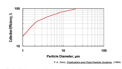
The figure below confirms that the cyclone efficiency falls by almost a factor of 10 for a 20-micron particle versus a 1-micron particle. As a result, two catalysts which have the same attrition index can have much different particulate emissions, depending on whether micro fines are generated during attrition versus particles in the 5-to-20-micron range.
Cyclone Efficiency vs. Particle Diameter
The 0 to 20 micron and 0-to-40-micron content of the fresh catalyst is also critical to ensure low particulate emissions from a third stage separator. These particulate fractions should be minimized within the constraints of the catalyst circulation system. (Many units need higher fresh fines content to ensure stable catalyst circulation.)
A catalyst with a higher particle density, not necessarily higher apparent bulk density, will increase TSS efficiency. Al2O3 content can be used to increase the particle density.
An article entitled Optimizing your FCC Regenerator Operation and Catalyst Design Can Minimize Catalyst Losses provide a detailed review of many of the issues discussed above. (1)
Grace recommends our Al-Sol catalysts such as ALCYON®, IMPACT®, GENESIS®, AURORA®, and AdVANTA® for units which use third stage separators. Worldwide, Grace supplies more FCC units with third stage separators than any other catalyst supplier. While we are the world’s largest supplier of FCC catalyst, our market share of units using third stage separator devices is even larger. This market advantage is a testament to the fundamental advantage of Grace catalyst and our Al-Sol catalyst, in particular, for minimizing emissions from third stage separators.
1. Hunt, et. al, “Optimizing your FCC Regenerator Operation and Catalyst Design Can Minimize Catalyst Losses”, Catalagram® 90, 2002.