Question 85: What operating practices or technology upgrades are you using to manage coking in the reactor overhead line at the main fractionator inlet?
SINGH (Indian Oil Corporation Limited)
Feedstock, catalyst, and reactor hardware all play a very major role in the vapor line coking. Coking of the reactor overhead line is a major concern, particularly when we are processing resids. Catalyst formulations designed for higher hydrogen transfer reactions, coupled with high aromatic feed, tend to produce higher boiling point PNAs (polynuclear aromatics), which have a tendency to condense and form coke in the vapor line. Design and configuration of the vapor line is also a very important factor.
There are different reasons that are all extremely unit-specific for vapor line coking, and they can predominantly be classified into two categories. Number one is factors leading to the presence of components which tend to produce coke at the reactor outlet. These factors include heavier feeds, aromatic feeds, improper atomization, post-riser cracking, high residence time in the reactor, low activity of the catalyst, comparatively more thermal cracking, etc. The other factors are related to the configuration and design of the reactor vapor line which influences condensation and coking. The phenomena of vapor line coking get aggravated by cold spots in the reactor vapor line, improper insulation, damaged insulation, low velocities, improper slope, cool patches in the vapor line, etc.
We have experience operating both hot- and cold-walled vapor lines, as well as a variety experience has been that even with the old design of the feed injectors, the extent of vapor line coking was much less while processing VGO in comparison to processing resid feed with modern atomizers, thereby indicating the significance of the type of feed on vapor line coking. In one of the units, the configuration of the vapor line was such that it had too many cold spots. It had the worst slope, and we had the tremendous problem of coking in the vapor line, though the unit did have a modern feed injection system. After correcting the problems related to the vapor line, to a very large extent, the problem could be eliminated. Hence, type of feed and vapor line configuration are important factors regarding vapor line coking.
Some suggestions to avoid this problem: We need to start with the best feed vaporization. Avoid mixing slurry with the feed. While using slurry filters, it is recommended to use feed as the backwash medium rather than HCO to avoid having the once-cracked material going back to the riser. Avoid cold spots in the vapor line and based on the design, insulate the vapor line well. During insulation, special attention should be paid to supports, manways, fittings, and flanges. Avoid cooling the vapor line with cool purge streams. In one of our units, we had to provide some steam purges in the vapor line that significantly enhanced coking within the line. Some old designs might have some purges or bypasses going in the vapor line which, again, should be avoided.
REYNOLDS (Phillips 66)
I will just reemphasize one point. Yes, you want to make sure you minimize all of the heat sinks on the overhead line. I recommend you do regular infrared scans or thermography and look for hotspots. Do that annually, quarterly, or some other frequency, which is especially important after a turnaround. Make sure you get a good quality baseline infrared scan, so you have a baseline of where you started. I think the dew point in the overhead vapor lines is also 600 to 700°F or so. You want to make sure you stay well above that temperature.
ZIAD JAWAD (Technip Stone & Webster, Process Technology)
Obviously, there are a lot of technology options available to help you minimize coking. It is really difficult to measure pressure drops across the vapor line. Typically, you are limited to instrumentation measuring single pressures, and you then have to subtract those pressure measurements. Obviously, you can take pressure at the top of the plenum; and on the main fractionator, you may not have a spot. So, you might want to think about having some dedicated tubing, if it is not short, to have an actual DP (differential pressure) at the top of the level bridle to get a downstream pressure.
W. LEE WELLS (LyondellBasell Industries)
The actual question stated that the main fractionator inlet was the concern. I did not write the question, but we have a similar concern. It is not on the line itself; it is only right where it goes into the fractionator in the dead spot. The line comes in from the side and elbows into the main fractionator. On the inside of that sweep, there is a dead spot that tends to build up coke, which breaks off and fills up the bottom of the main fractionator. Does anyone have an answer as to why that occurs? Also, has anyone else seen coke buildup in the same location? Obviously, someone else submitted this question.
WARREN LETZSCH (Technip USA)
Yes, we have done that. [Laughter] It is not uncommon to get a donut around the inlet to your main fractionator. In our old units, I have seen areas where we have built up a five-pound pressure drop across the donut. I think it has a lot to do with the velocity going into the main fractionator – whether it is too low or too high or if it is sloped properly – and the insulation around it. Frankly, that has been addressed in the old NPRA/AFPM transcripts.
I will just tell you about one even more interesting situation. You know, when you guys get your FCC units, you go to the licensor. He gives you a process design package, and then you go to the detailed engineering company. You think the detailed engineering company personnel are experienced and know what they are doing. Here is your reactor coming out with the main overhead vapor line, and you thought you would go into the main fractionator. Oh, no! This guy was really clever. He came out down and put it in the pipe rack. It went around and then came all the way around to the back of the fractionator, and you ended up with about a 300-foot vapor line. He was complaining about coke in it. [Laughter] Actually, it was quite a good condenser, particularly if you put it into a place with a tropical climate and where you can get two inches of rain in an hour or so. It is a terrific condenser. These situations really do happen.
RICHARD RUSSEFF (CVR Refining, LP)
I have seen a similar phenomenon right at the blind flange location on the tower where the coke tends to build up and then streak into the tower building, creating a good pressure drop. We had that same issue, which we ended up solving with a combination of steam rings and insulation to try and eliminate that spot during normal operations. However, it was quite a bit to chisel out. It was very odd shaped because it had started at the flange and then worked its way into the tower, making horizontal stalactites on its way into the tower. Is that the same situation you saw?
W. LEE WELLS (LyondellBasell Industries)
We do not have a flange in that location, and we do not see stalactites.
ROBERT (BOB) LUDOLPH [Shell Global Solutions (U.S.), Inc.]
We have seen a variety of coke formations pinching the main fractionator inlet, creating pressure drop between the top of the reactor and the top of the main fractionator. Shell did a review of what might contribute to the coke growth and concluded that the velocity was a player. However, the ranking of the process parameters suspected as coke growth contributors is quite site-specific. We have conducted CFD analysis to better understand what might be occurring, but we are not satisfied with the results. Suspected locations and causes of pressure drop increases are, many times, unconfirmed when the equipment is entered during turnaround. Remediation and prevention of main fractionator inlet coking remains a big area of learning for us.
SANJIV SINGH [Indian Oil Corp Ltd. (IOCL)]
Feedstock, catalyst, and reactor hardware all play major roles in vapor line coking. Coking of the reactor overhead line is of most concern when processing residues. Catalyst formulations designed for high hydrogen transfer reactions, coupled with heavy aromatic feedstocks, tend to produce higher boiling point PNAs, which have a tendency to condense and form coke in the reactor vapor line. Design and configuration of the vapor line also plays a very major role in its coking.
Though the problem of vapor line coking is unit-specific, there are two major factors contributing towards reactor vapor line coking:
-
Presence of components having higher tendency to coke at reactor outlet: Heavier feeds, aromatic feeds, improper atomization, post-riser cracking, high residence time in the reactor, low activity of the catalyst, and comparatively higher thermal cracking are the major contributing factors to enhance vapor line coking.
-
Configuration and design of reactor vapor line influencing condensation/coking: Cold spots along the vapor line (caused by improper/damaged insulation, exposed fittings, etc.), low velocities, improper slope, and cold purges in the vapor line enhance vapor line coking. Sometimes high vapor velocity in the vapor line near the main column inlet results in column bottom material getting sucked into the vapor line, leading to coking at that location. Attention should also be paid to the design and operation of the main column bottom section to avoid coking in the vapor line at column inlet nozzle.
At Indian Oil, we have experience operating both hot and cold wall vapor lines, as well as very old designs (bayonet/shower head) for VGO and modern feed injectors for VGO/resid. As per our experience, the problem of vapor line coking was considerably less while processing VGO even with shower head feed injectors. In comparison, while processing resid, vapor line coking occurs even with modern feed injectors. The problem occurs even with a cold wall design. In one of the units, configuration of the vapor line was an area of concern with too many cold spots and reverse slope. Coking in this line was considerable requiring very close monitoring of pressure drop across the line. Correcting the shortcomings, along with improved atomization of feed and higher catalytic activity, almost eliminated the problem.
Some suggestions to minimize/avoid vapor line coking are:
-
Start with the best feed vaporization. Optimize the atomization across the feed nozzle, avoid mixing slurry or other cracked stuff in the feed, ensure recycled slurry atomization, reduce the feed with heavy tail in VGO crackers, and maintain minimum feed preheat temperature. In units equipped with slurry filtration, using raw oil as back-flush medium instead of HCO would avoid recycling of high aromatic cracked material back to the riser. Operating the unit at possible high MAT (microactivity test) is desirable.
-
Avoid cold spots in the vapor line. Based on the design, insulate the vapor line well with special attention to line supports, manways, fittings, flanges, etc. Avoid cooling the vapor line with cool purge streams, including steam. Eliminate low points in the line which may accumulate and condense heavies. Some older designs had recycled back to the vapor line. These should be avoided. Cold wall design of the vapor line is preferred.
NIKOLAS LARSEN [Marathon Petroleum Company (MPC)]
For previous MPC information, see Question 36 from 2009 AFPM Q&A. Reactor vapor line coking is typically caused by low severity operation or poor feed atomization. Long-chain paraffins that survive the cat/oil contact and reactor conditions are prone to condensing on the vapor line at low reactor temperature and lead to coking. MPC has not experienced any vapor line coking due to low reactor temperature operations. However, we have guidelines to maintain an ROT higher than 930°F for all units (except resid units).
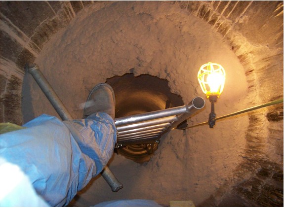
The only vapor line coking incident occurred because of condensation. A portion of a reactor vapor line was replaced during a scheduled unit turnaround. The transition between the hot wall and cold wall components was not properly insulated. This resulted in a cold spot where reactor vapors condensed and formed coke. The coke ring caused a 1.5 psi pressure drop. The problem was diagnosed from regular, single-gauge unit pressure surveys. A picture of the coke deposit is shown below.