Question 7: What are your potential strategies to increase refrigeration system capacity and throughput in sulfuric acid alkylation units?
SHARON (Valero)
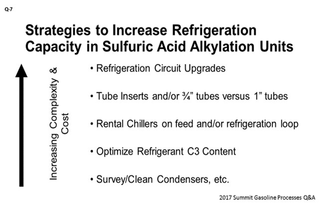
What you are looking at on the slide is a list of different options with increasing complexity and cost. The first – and obviously the most expensive – one is refrigeration circuit upgrades. Those are typically cost-prohibitive. This upgrade could be a compressor- or a condenser-related type of improvement.
Next on the list are the tube inserts. Tube inserts shift the throttling to the inlet of the tube versus your pressure controller on the settler for heat transfer. Some folks in industry have seen about a 15% improvement in heat transfer coefficient there, although we have seen some mixed results with this equipment providing benefit. You can also changeout your contactor tube bundle to utilize three-quarter-inch tubes versus one-inch tubes. This modification will get you about a 30% increase in surface area at the expense of tube life. If you have an older contactor or design, an option is to also put in an extended bundle, which will buy you some more surface area as well.
You can also consider the installation of rental chillers on the feed and/or a refrigeration condenser loop; like on the cooling water, for instance. That option [or addition?] can be fairly inexpensive. You can also optimize your propane content, which is typically about 10 to 15%. Obviously, the more propane that is used, the more reaction zone cooling that will be needed, at the expense of compressor requirements. Your last option is the survey of the clean condensers, which is typically an annual type of PM (preventive maintenance) activity that we do throughout our circuit.
JASON NUNEZ and KATE SMITH (DuPont Clean Technologies)
Several options are available to increase capacity and throughput in the refrigeration system of a DuPont STRATCO® effluent refrigerated alkylation unit. Depending on the specific limitation of the system – whether it be the capacity available from the refrigerant compressor, horsepower limitations of the refrigerant compressor driver, refrigerant condenser capacity or reactor tube bundle area, a specific solution may be tailored to help the refiner improve performance of the refrigeration system with minimal capital investment. A few of the options available include:
-
Optimizing refrigerant composition,
-
Replacing Contactor™ reactor 1” tube bundles with ¾” tube bundles,
-
Adding tube inserts to existing Contactor™ reactor tube bundles,
-
Adding DuPont proprietary XP2 technology to existing Contactor™ reactors,
-
Upgrading refrigerant condenser capacity with a compact welded plate and frame heat exchanger, and
-
Adding supplemental closed-loop chiller units.
Refiners may wish to improve refrigeration system performance with the goal of reducing reactor temperatures to maximize alkylate quality and minimize acid consumption or to increase olefin feed and maintain current reactor temperatures. Either way, DuPont STRATCO® can assist the refiner in determining the best solution with minimal capital cost for their application, which may include any one or a combination of several of these options.
The effluent refrigeration loop is a complex system, and optimization is dependent upon suction trap/flash drum pressure and composition of the refrigerant. Decreasing the suction trap pressure will decrease the bubble point temperature of the refrigerant recycle and the reactor tube bundle effluent. As the bubble point of the refrigerant is lowered, the Contactor™ reactor temperature also decreases. As a rule of thumb, decreasing the suction trap/flash drum pressure by 1 psi will decrease reactor temperature by 2.5°F. The composition of the refrigerant also influences the effluent vaporization temperature. A lower propane concentration in the refrigeration loop results in a higher bubble point temperature of the effluent flashing in the Contactor™ reactor tube bundle and consequently a higher reactor temperature. However, as propane concentration increases in the refrigerant loop, the required compressor discharge pressure required to condense the stream in the total condenser also increases. Typically, condensing limitations are the initial indication of a refrigeration system that is at capacity.
-
Propane content in the refrigeration loop can be manipulated by adjusting the feed flowrate to the depropanizer tower (or the flowrate of the propane purge stream for alkylation units that do not have a depropanizer). Since this stream is the primary way that propane can leave the alkylation unit, increasing the feed flowrate to the depropanizer tower will lower the propane content in the refrigeration system while decreasing this flow will increase the propane content in the refrigeration system. Alternatively, the depropanizer bottom temperature can be lowered to allow more propane to slip into the bottom stream; however, this may negatively impact propane product composition. Even for alkylation units with very little propane in the feed streams, either of these process variables can be manipulated to allow propane to build in the refrigeration system.
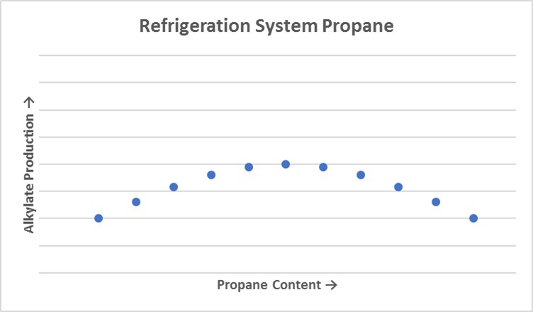
Figure 1. Refrigeration System Propane
DuPont recommends a structured test run and sensitivity analysis to determine the optimum propane content for each unit. Unit data can sometimes be utilized to obtain a general understanding of where the optimum propane operating point lies. The refiner may be able to plot depropanizer feed propane composition versus alkylate product flow rate. If sufficient data is available, a graph – such as Figure 1 – such be generated, and optimum propane composition can be determined. If sufficient data is not available to generate a graph such as this, a test run will be required. Propane optimization is the first step in refrigeration optimization; however, equipment modifications may be necessary to provide adequate cooling in the reaction zone.
-
One equipment modification option available to refiners is to replace existing 1” Contactor™ reactor tube bundles with ¾” tube bundles. Typically, a ¾” tube bundle can fit nearly twice as many tubes in each shell ID (interior diameter) as a 1” tube bundle and provide 35 to 40% more surface area.
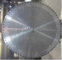
Figure 2. 1"-Tube Bundle with 613 Tubes
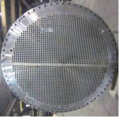
Figure 3. ¾"-Tube Bundle with 1093 Tubes
Increased velocity of the net effluent flowing through the inside of the tubes, due to a smaller inside diameter, will also increase the Contactor™ U-value by about 5%. As a result, a refiner can achieve a 4 to 6°F decrease in reactor temperature at the same olefin feed flow or a 10 to 12% increase in olefin feed flow at the same reactor temperature.
-
Another option refiners may consider is adding tube inserts to the Contactor™ reactor tube bundles. Tube inserts are installed into the bottom half of the tubesheet tubes (tube bundle inlet) and provide an even distribution of the two-phase settler effluent stream.
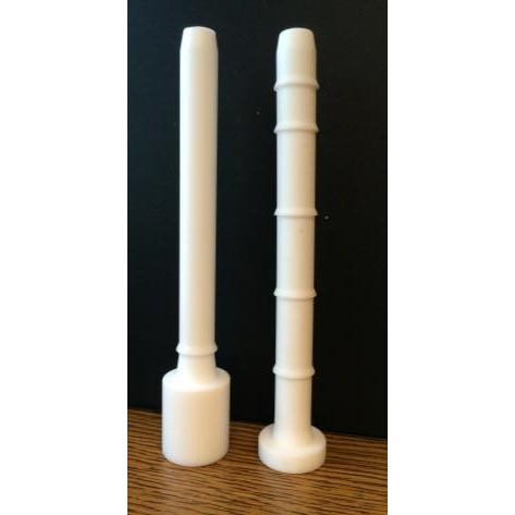
Figure 4. Tube Inserts
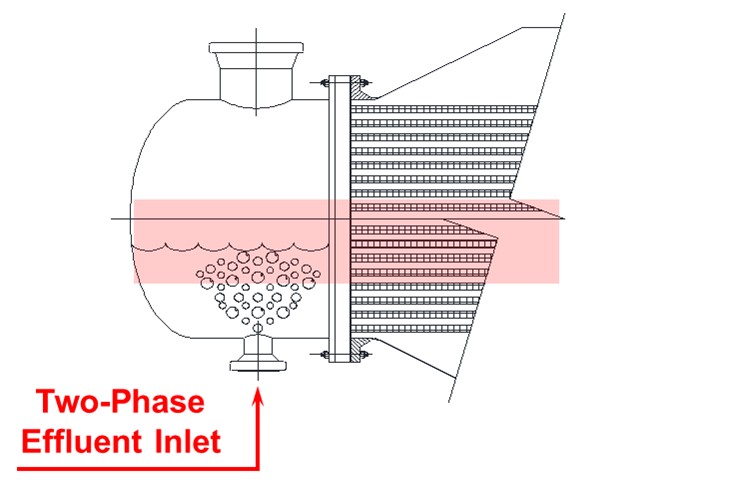
Figure 5. Maldistribution and Hot Spots without Tube Inserts
4. Without tube inserts installed, maldistribution of liquid and vapor at the tube bundle inlet creates three distinct zones within the tube bundle with some tubes receiving only vapor flow and some tubes receiving only liquid flow while most tubes receive two-phase flow. Since the latent heat of vaporization of the settler effluent stream provides the bulk of heat of reaction removal, the tubes with only vapor flow provide almost no heat transfer from the reaction zone and typically operate at a higher temperature than the remaining tubes. Tube inserts function to equally distribute two-phase flow to each reactor tube, allowing for 100% utilization of the available effective heat transfer area. The tube insert orifice diameter is sized so that flashing occurs across the tube inserts rather than across the upstream pressure control valve. While the pressure control valve will still take some pressure drop so that settler pressure can be controlled, most of the pressure drop will occur across the tube inserts. As a result, a 15 to 20% increase in tube bundle U-value can be observed. Installation of tube inserts will typically allow a refiner to decrease reactor temperature by 2 to 4°F at the same olefin feed rate or increase olefin feed rate by 5 to 7% at the same reactor temperature. In addition to the reactor temperature or olefin feed benefit, proper distribution of the two-phase flow eliminates potential “hot spots” (typically at the 3 o’clock and 9 o’clock positions), reducing tube bundle corrosion in these areas and increasing tube bundle life.
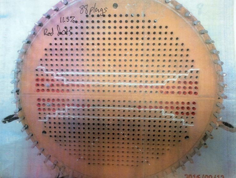
Figure 6. Tube Bundle Corrosion at 3 o’clock and 9 o’clock Positions
Another option available to increase refrigeration system capacity is adding DuPont proprietary XP2 technology. XP2 technology extends the Contactor™ circulation tube increasing effective surface area by providing improved flow distribution toward the tubesheet and the bundle center.
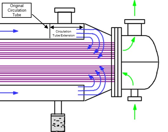
Computational Fluid Dynamic modeling of flow patterns on the shell side of Contactor™ reactors revealed areas of stagnation around the tubesheet and toward the center of the tube bundle. These stagnant zones are areas where heat of reaction is not effectively removed allowing for side reactions to occur, which increases alkylate end point and negatively impacts acid consumption. Extending the circulation tube improves flow in these areas and minimizes these negative side reactions. XP2 installation has been proven to increase effective surface area, lower end point, and reduce acid consumption. Typically, a refiner can expect to see a 1.5 to 3.5°F decrease in reactor temperature at the same olefin feed flowrate or a 3 to 12% increase in olefin feed flowrate at the same reactor temperature when XP2 is installed.
-
Refiners who are limited by condensing capacity in the refrigerant condensers, either due to surface area or cooling water supply, may consider replacing existing shell-and-tube heat exchangers with compact welded plate-and-frame heat exchangers.
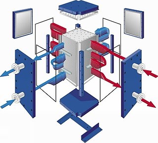
Figure 8. Compact Welded Plate-And-Frame Heat Exchanger
Compact welded plate-and-frame heat exchangers allow for true counter-current flow and a significantly tighter approach to cooling water temperature. Lowering the refrigerant condenser outlet temperature will lower the refrigerant accumulator pressure and the compressor discharge pressure. This modification will shift the operating point on the compressor curve to either unload the compressor, resulting in decreased suction trap/flash drum pressure and reactor temperature or shift compressor inlet composition, creating a lower compression ratio and higher compressor throughput for the lower condensing temperature.
-
Another option available for refiners is to strategically install closed-loop rental chillers. This is generally an attractive option because the capital cost to install necessary infrastructure to support the chiller units is very small and the cost to rent these units can be moved out of capital and into operating expense. The size of the chiller unit can be custom-tailored to the requirements of the refiner. With relatively low annual costs and potentially substantial increases in olefin feed flowrate, these units are easily justified. Typically, chillers are installed on the combined olefin and isobutane feed stream to the alkylation unit upstream of the feed coalescer. Chillers are normally designed to decrease the combined feed temperature to around 38 to 40°F, lowering the sensible heat load of the reactors and, more importantly, allowing for maximum water removal from the feed to the reaction zone. These two benefits lower reactor temperatures, allowing more olefin feed, as well as significantly reducing corrosion rates in the reactors. Other locations where chillers are beneficial are in the refrigerant loop, downstream of the refrigerant accumulator, and on the refrigerant return line from the depropanizer bottoms. If refiners already have coolers installed in these services, then the cooling water can be replaced with chilled glycol, affording a lower process temperature than possible with cooling water and making more cooling water available for the rest of the alkylation unit. Lowering the temperature of these streams decreases the fraction of the refrigerant stream that flashes in the compressor economizer and/or in the flash drum side of the suction trap/flash drum, effectively unloading the compressor and allowing the refiner to process additional olefin feed. Refiners may also elect to install chillers to either replace cooling water to the refrigerant condensers with chilled glycol or to sub-cool the refrigerant condenser process outlet stream, thereby lowering the refrigerant accumulator pressure and providing similar benefits discussed previously for compact welded plate-and-frame heat exchangers in this service.
With so many options available to increase capacity and throughput in the refrigeration system of a DuPont STRATCO® effluent refrigerated alkylation unit, selecting the best option (or combination of options) can certainly be a daunting task. Refiners can rest assured that DuPont is here to assist in determining the most cost-effective solution available to meet refinery goals.
RICHARD TODD (Norton Engineering Consultants, Inc.)
One option for a direct-refrigeration (i.e., Kellogg or ExxonMobil)-style reactor that has a multi-stage compressor is to install an economizer drum and preflash the circulating refrigerant stream to compressor inter-stage pressure prior to the refrigerant stream entering the reactor. This preflash step will decrease refrigerant temperature and direct vapor boil-off to compressor inter-stage suction, freeing up compressor first-stage suction capacity at low pressure for boil-off across the CSTR (continuous stirred tank reactor) stages of the reactor. This preflash will reduce overall reactor temperature and improve alkylate quality/throughput by (a) reducing vapor load to the first stage of the refrigerant compressor, (b) decreasing refrigerant temperature entering the reactor, and (c) allowing the reactor to potentially operate at lower pressures, thereby reducing bubble point of the sulfuric acid/hydrocarbon emulsion.