Question 64: Based on your experience, what are causes of fouling in the diesel/distillate draws of crude, vacuum, and coker fractionation towers? Does this migrate to downstream diesel hydrotreating units? What mitigation strategies are being employed to overcome these issues?
LEE (BP North America)
We have been concerned with potential phosphorous fouling on units processing Canadian heavy crude oil. We are aware that some refiners have experienced and reported on significant phosphorus fouling issues in the light diesel or jet draw section of the crude tower, as well as in the crude furnace. While we are concerned with the issue and monitor for it, we have not had any particular callout issues with CDU phosphorus fouling. In our view, the fouling of interest in the diesel draw section is differentiated from the amine or ammonia salt fouling that we typically see in the cooler top section of the tower. These particular salts condense at colder temperatures about less than 300°F, and we have not typically seen issues with these salts in the diesel section except for a particular example that I will describe shortly.
We have converted from conventional moving valve trays to fixed valve trays in the diesel section of a crude tower to help mitigate fouling. However, we have not yet definitively demonstrated the benefit of the modification as it is difficult to achieve site-by-site comparative conditions for doing such. This is a preemptive type of tower internals modification.
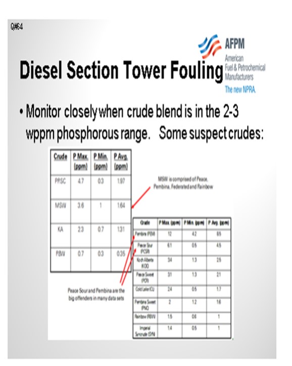
Many of our refineries are particularly concerned with any downstream unit impacts. We take phosphorus samples in our CDU products and closely monitor if issues are suspected or if there is a phosphorous-bearing crude scheduled or suspected to be in the crude supply. In the table below, you can see examples of some suspect Canadian crudes. The phosphorous contents are shown for these crudes. We monitor unit health and operations closely on our CDU blends that are in the 2 ppm to 3 ppm phosphorous content range.

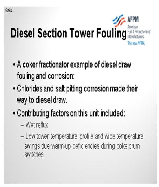
Let me add that one example I said I would give you. In this case, we did get some diesel section salt fouling. This one happened to be on a coker diesel draw tray. We saw nozzle corrosion on this unit that was due to chloride and salt pitting corrosion and which was the result of both wet reflux and lower tower temperature profiles during drum swings. This particular coker has had issues with wider-than-typical temperature swings during the coke drum switches and a relative deficiency of warmup capacity, both of which contributed to the lower temperature profile seen on the coker fractionator. So, chlorides in this coker naphtha and diesel products did find their way to downstream units in this particular refiner.

BASHAM (Marathon Petroleum Corporation)
We experienced a similar situation as Howard just mentioned. At our Robinson Refinery crude unit, we have seen phosphorous fouling over the kerosene section for about three to five trays. We also had floating valves that we replaced with a fixed valve design to help out with that fouling as well. In a coker fractionator tower, it is important that, as Howard said, you do not let the overhead temperature get too low; because when you force the colder temperatures down in the tower, you can see the salt formation in the distillate section.
DION (GE Water & Process Technologies)
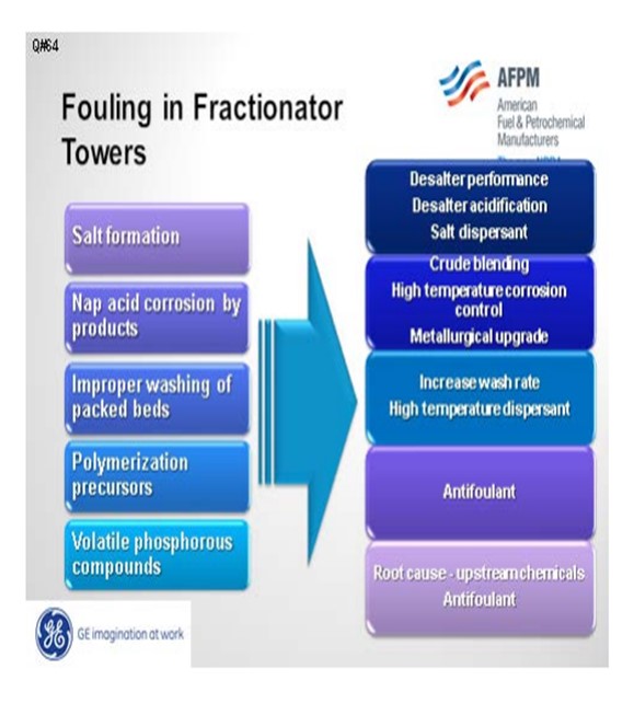
Fouling in the distillate trays and other locations can be divided into five different categories: salt, corrosion byproducts, coke, polymers, and volatile phosphorous compounds. Amine salt fouling can be mitigated with improved desalter performance, removal of tramp amines, and the use of a salt dispersant. Acidifying the desalter will partition a greater number of amines into the effluent brine.
If you do not have the proper metallurgy, corrosion byproducts can foul downstream units. This can be addressed with metallurgical upgrades and high temperature corrosion control programs, as well as blend control to minimize the TAN (total acid number) and NAN (naphthenic acid number) of the crude blend.
Improper washing of packed beds can contribute to fouling. This condition is usually seen in vacuum towers that have high surface area and very high molecular weight heavy hydrocarbon molecules that may precipitate, dehydrogenate, and create coke. This fouling can be addressed operationally with wash rates and the use of a high temperature dispersant to move coke particles.
Bitumen streams, such as dilbit from Canada and DCO (diluted crude oil) from Venezuela, may have the potential to induce polymerization. These crudes are typically bitumen with a diluent added to reduce viscosity. If these diluents come from cracking processes, there is the potential that they may contain olefins which could encourage fouling from polymerization products.
Howard addressed volatile phosphorus. These are most likely from phosphorus-based oil field chemical additives.

AHMAD AL-JEMAZ (Kuwait National Petroleum Company)
Again, I want to ask about mitigating fouling in the coker fractionator. Also, how effective is the introduction of online antifoulants to clear the fouling material created from corrosion products or coke fines and salts? Is there any record of successful implementation of antifoulants to clear the fractionators?
DION (GE Water & Process Technologies)
It is easier to prevent fouling from occurring than to remediate after the fact. An example is asphaltene precipitation. It is easier to prevent asphaltene molecules from agglomerating to a size where they precipitate than it is to redisperse them once they are agglomerated. Sloughing the tower to wash fouling material out of the system is usually a last resort. A better approach would be to examine methods to minimize coke entrainment into the tower including: an effective coker defoamer, defoamer to diluent ratio, coker overhead corrosion inhibitors, upward vapor velocities in coke drum vapor line, and an antifoulant in the gas oil or other reflux.
CELSO PAJARO (Sulzer Chemtech USA, Inc.)
For our delayed coker main fractionator, we have successfully used antifouling trays (VG AF™). They have several advantageous characteristics to mitigate fouling including fixed valves, push valves, fouling-resistant downcomer designs, and special outlet weirs. These features generally resist fouling and/or serve to move sediment across the trays to minimize accumulation of these fouling components.
LEE (BP North America)
I have one other comment on the first question: the use of antifoulants. Maybe the vendors know more about this, but I think there is some literature or some publications where folks have successively used iron dispersant to move around the iron scale. We considered that for the salted-up tower we had; but to us, it felt very much like a last resort because if we moved those solids to a draw nozzle or somewhere else, we would be shutting down the unit. So, we considered it, but we thought it was too risky to try.
BASHAM (Marathon Petroleum Corporation)
At Marathon Petroleum Company, the only issue we have had is the phosphorus fouling in our Robinson refinery crude tower, which only occurred over three to five trays in the kerosene section. We have reason to believe that phosphorus will migrate to both the kerosene and diesel sections, thus affecting the diesel hydrotreater. However, only the volatile phosphorus is believed to result in tower fouling. We replaced the trays (floating valve) with an antifouling fixed valve design.
DION (GE Water & Process Technologies)
There are five primary ways that foulants can be generated and deposited in the diesel/distillate sections:
Salt Formation: With more focus on diesel maximization, more tower operations have been changed to run at lower overhead temperatures. The shift in tower operation coupled with tramp amines either in the crudes or recycled via other streams can cause salting in the tower. The salts will foul the tower and since they are very corrosive, will end up generating corrosion byproduct which will also contribute to the fouling.
Naphthenic Acid Corrosion: Naphthenic acids can distill and concentrate in these cuts. If the temperature is high enough and the metallurgy has not been properly upgraded (SS 316L and SS 317L), corrosion will occur. Depending on the severity of the corrosion, the fouling rate from corrosion byproducts can be quite significant.
Improper Washing of Packed Section: This typically happens more in vacuum towers where packed beds are more common. There is more surface area for compounds such as asphaltenes and other heavy molecular weight material to deposit and dehydrogenate forming coke. Some of the coke fines will end up going with the draw and can foul the downstream exchangers.
Polymerization Precursors: With the increased availability of dilbit, synbit and diluted crude oil, there is an increased risk the diluent used for these synthetic crude or bitumen products are from cracking processes. If the diluent is from a cracking process and either not hydrotreated or the hydrotreater is not completely efficient, polymerization precursors can be present.
Volatile Phosphorous Compounds: With the increased availability of unconventional crudes, fouling from volatile phosphorous compounds is becoming more prevalent.
All of these foulants and foulant precursors have the potential to impact downstream units.
Mitigation Strategies
1. Salt formation:
a. Desalter performance improvement (chloride reduction)
b. Desalter acidification to reduce tramp amines
c. Salt dispersants
2. Naphthenic corrosion:
a. Crude blending to reduce naphthenic acid content
b. High temperature corrosion control program (chemical treatment)
c. Metallurgical upgrades
3. Improper wash:
a. Increase wash rate.
b. Apply high temperature dispersant.
4. Polymerization precursors
a. Apply antifoulant chemistry to minimize polymerization.
5. Volatile phosphorous
a. Perform root cause analysis of upstream chemical additives to minimize or eliminate the risk.
b. Apply of antifoulant chemistry, such as dispersant, to minimize fouling due to phosphorous compounds.
BRUCE WRIGHT (Baker Hughes)
Salt deposition is the most common. Both ammonium and amine chloride salts have been identified. The salts most likely will not migrate downstream, but can lead to additional iron sulfide formation, via underdeposit corrosion, which has been seen to migrate downstream. The deposition of the salts is a function of temperature and concentration. Identification of the operating window in which salts will deposit can be determined by use of the Baker Hughes Ionic Model. The Ionic Model can also be used to select the most appropriate neutralizer to reduce salt deposition for the operating window. Baker Hughes salt dispersant additives have also been successfully employed. iron sulfide fouling is also not uncommon. Effective mitigation has been achieved with Baker Hughes corrosion inhibitors and/or iron sulfide dispersant additives. Organic phosphorus compound deposition has also been experience. Both mitigation and online cleanup have been achieved with Baker Hughes additive application.
DENNIS HAYNES (Nalco Energy Services)
Diesel/distillate draw fouling in distillation columns is distinct from the problems reported in the literature for naphtha section fouling. Fouling that has been seen at this area lower in the tower, in certain cases, has been related to some specific chemicals used in the production of crude oil. The Canadian Crude Quality Technical Association has done projects in this area over past years. Where the fouling has become apparent in columns, dispersant type chemistries have been successful in reducing material buildup.
SAM LORDO (Nalco Energy Services)
In this part of the tower, amine/ammonia salting is the primary fouling encountered. The following has been done to minimize this type of following:
• Raise tower overhead temperatures,
• Optimize desalting operation to minimize chloride and/or amine traffic in the tower, and/or,
• Use salt dispersant chemistries.