Question 47: Are there any operational parameters that can be manipulated to improve the operation of the slurry circuit and minimize fouling? Can you outline the slurry exchanger circuit recommended design practices to minimize fouling, plugging and erosion?
MINAZ MAKHANIA (UOP)
Fouling in slurry circuit is commonly caused by coking. Three main variables affecting coking in the slurry circuit are: Composition, Residence time and Temperature.
Temperature: From experience, the rate of coke build-up increases greatly when the bottoms temperature is > 700F (370°C). It is recommended to maintain the bottom's temperature below 680°F (360°C) to be on the safe side. Often while processing highly paraffinic feedstock, 660°F (350°C) is a good starting point for MCB temperature and it can be optimized based on monitoring of heat transfer coefficients of the exchangers in the slurry circuit. Use quench a very low slurry API is required (e.g., for CBFS).
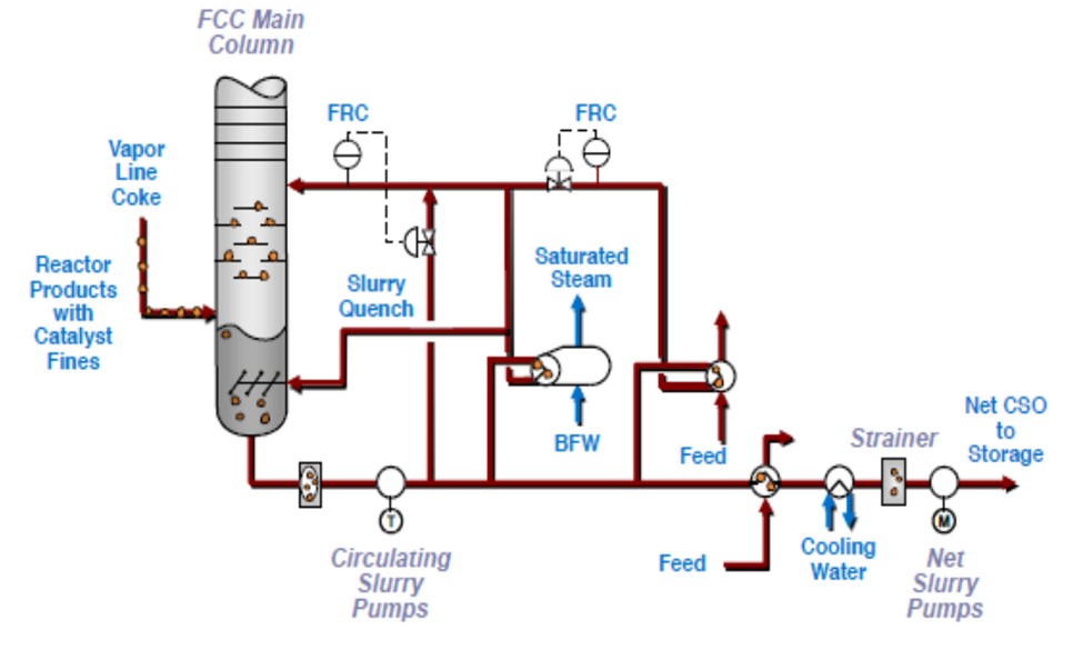
Minimize the level in the main column bottoms to reduce residence time. Typically, the minimum circulation rate required to prevent coking is 6 gpm/ft2 (14.67 m3/hr per m2) of column cross-sectional area but not less than 150% of the design feed rate for disc and donut trays to ensure trays stay wetted. UOP provides a hot bypass to help maintain the pump around rate without affecting main column heat balance.
More saturated slurries decompose at lower temperatures, increasing reactor temperature and catalyst activity to eliminate coking through this mechanism.
When running heavy feeds with a low matrix activity catalyst at low conversion, it is still possible to minimize coking with control of operation in the main column. As an initial guideline, UOP recommends that the light cycle oil draw rate be controlled to limit the slurry gravity at a minimum of -2°API or the slurry viscosity at a maximum of 25 cSt at 99°C.
Usually, slurry catalyst content does not directly cause coking problems. To prevent catalyst plugging or erosion in the exchangers, UOP recommends maintaining a maximum velocity of 8.0 ft/s (2.44 m/s) and a minimum velocity of 4.5 ft/s (1.37m/s) in the slurry exchanger tubes.
In general, the optimum velocity is 5.7 ft/s (1.75 m/s). Straight tube construction is recommended.
ALEC KLINGHOFFER (Coffeyville Resources)
Two main causes of FCC slurry circuit fouling:
Minimize coke formation.
-
Proper feed atomization.
-
Operate main fractionator bottoms temperature between 650 – 700°F.
-
Monitor asphaltenes in FCC feed.
-
Catalyst Particles
-
Set minimum flow rates through slurry circuit.
-
Monitor catalyst properties for signs of attrition.
SAEED ALALLOUSH (Saudi Aramco)
There are a couple of operating parameters that could improving the fouling rate in the slurry loop like slurry fluid velocity inside the slurry exchangers. Also, the design of the slurry exchangers can improve the fouling rate. Additives can also be used to minimize the fouling.
MICHAEL FEDERSPIEL (W. R. Grace & Co.)
Slurry exchanger fouling comes in several forms, which can be broken down into either organic or inorganic fouling. Inorganic fouling can be caused by corrosion products, precipitated metals, or catalyst particulates in the slurry circuit. Organic fouling, which is more common, can be caused by coke deposits or asphaltenes that have precipitated from the slurry.
Understanding and addressing the root causes of the different types of fouling can help minimize their impact on FCC operations. Using the correct metallurgy in the main fractionator and slurry circuit will significantly reduce corrosion. By closely monitoring antimony injection, a refiner can reduce the risk of antimony accumulation in the main fractionator.
By maintaining cyclone physical integrity and operating at proper cyclone inlet velocities, a refiner can reduce the contribution of catalyst particles to slurry fouling. It is also worthwhile to pay attention to catalyst and additive attrition index and particle size distribution as these can both impact losses to the main fractionator.
Time, temperature and composition of the slurry all contribute to coke formation and steps can be taken with each of these parameters to help minimize slurry fouling. Ensuring proximity of slurry exchangers and avoiding unnecessarily long slurry piping runs can reduce the amount of time slurry spends at elevated temperature. The temperature in the slurry circuit can be reduced using slurry quench. It is recommended to calculate and monitor the bubble point temperature of the slurry while using slurry quench as an indication of the slurry composition. Ensuring good distribution of the slurry circuit return to the main fractionator and maintaining a slurry pumparound rate such that the wash trays are always sufficiently wetted will also reduce the chances of coke formation. Finally, undercutting LCO into the slurry product will both reduce the temperature and lead to a directionally lighter slurry composition.
Asphaltene precipitation can occur when the asphaltene concentration increases (which can be due to feed type) or if the solubility of those asphaltenes is reduced. Asphaltenes are more soluble in highly aromatic environments, while the presence of more saturated compounds reduces this solubility and leads to fouling. Loss of conversion due to lower catalyst activity or reactor severity can lead to more saturated compounds in the slurry, so addressing loss of conversion is a solid strategy for reducing slurry fouling.
Grace published a thorough paper titled “Understanding and Minimizing FCC Slurry Exchanger Fouling” in Catalagram Number 101, Spring 2007. In it, the causes of the above types of fouling are discussed in more detail, along with mitigation strategies and design considerations. It can be found at this link: https://grace.com/catalysts-and-fuels/en-us/catalagram
References
1) Hunt, D., Minyard, B., Koebel, J., Davison Catalagram 101, Spring 2007, pp 30-36.
RAUL ROMERO (NALCO)
Comparison of current operating process variables on slurry/bottom P/A system with design ones should be a first step to assess operating gap and justify and understand any change. Some parameters like temperature profile through washing, sheds area and bottom systems, bottom residence time, P/A flowrates and heat exchanger velocities are key. Control stability of flows and temperature associated with above mentioned sections mitigate “coke spalling” situations leading to a sudden plugging of heat exchanger and pump filters. A thorough antifouling chemical program has demonstrated good success in preventing coking formation and catalyst deposit. This program should be preceded by a specific lab test program to identify the best solution for specific slurry properties.