Question 46: What is your strategy to minimize main fractionator bottoms (DCO/ Slurry) versus LCO production apart from feed quality/catalyst selection?
DEWEY STUART (Motiva Enterprises)
The primary operational handles to minimize bottoms production is optimization of the cat to oil in the R&R. As the C/O is increased more of the heavy oils will be converted. As with all good things in the FCC this can be taken too far. Limits can be reached on the actual operating equipment in this process. Be aware of safe operating temperature windows of the risers/reactor, regenerator and fractionator. As less bottoms are produced the quality will shift. This can lead to increased foulant in the heat exchanger circuit and additional maintenance. Many refineries do not have double isolation on these systems which can cause significant hazards as the blinds are installed and removed. Minimizing the amount of work on this type of equipment during the run reduces the potential for personnel exposure. Additionally, the lower rate results in higher concentrations of catalyst fines due to relatively constant catalyst losses. This is one of the reasons for the increased fouling rates. The fines are also abrasive leading to increased erosion in the pump around circuit especially in the control valves and piping elbows.
Simple distillation cut point control is another method. This will directly affect the shift from bottoms up into the LCO circuit. This can be controlled with the quantity and quality of the bottoms pump around circuit. As mentioned above this can lead to quality shifts in the circuit and must be balanced with the negative effects. Additionally, if not careful in the approach method this will lead to high temperatures in the bottom section of the tower.
MINAZ MAKHANIA (UOP)
There has been increased emphasis on reducing slurry make with the looming IMO specifications that are expected to take effect in 2020. In addition to adjusting operating conditions or catalyst formulation, you can recover more LCO from slurry.
To minimize main fractionator bottoms vs. LCO production, the key is to pull maximum possible LCO subject to main column bottoms section constraints.
As an initial guideline, UOP recommends that the light cycle oil draw rate be controlled to limit the slurry gravity at a minimum of -2°API or the slurry viscosity at a maximum of 25 cSt at 99°C. These guidelines can be altered based on fouling observed in the slurry circuit by monitoring heat transfer coefficients of slurry circuit exchangers. Units have operated at -8 API and >50 cSt viscosity at 99°C.
When it is required to pull more LCO to meet very low slurry API for carbon black feed stock specifications, high main column bottoms temperature will be required and, in such situations, to prevent main column bottoms coking, quenching or sub cooling of the slurry is done by cooled slurry exiting one of the steam generators. Quench distributor and piping are included in UOP design.
Some refiners have installed vacuum flash columns to recover more cycle oils. UOP is currently evaluating alternative technology. Another option to reduce or eliminate slurry production from an FCC unit is to send it to a UOP Uniflex Unit.
SAEED ALLLOUSH (Saudi Aramco)
Feed and catalyst selection should also be considered for longer term optimization. Feed contains more heavy components that would be more difficult to crack it to lighter products. It could be measured by the naphthene contain, UOP K factor, metal contain, and ConCarbon, which these are the primary factors effect FCC feed crackability to lighter products including LCO and Gasoline. Catalyst selection is dependent on the required cracked products and the catalyst design technology. Every catalyst has different compositions of zeolite and formula used in the catalyst design to give different reaction yield.
ANDREW SLOLEY (Advisian, Worley Parsons)
Operation strategies for the main fractionator to make less slurry/DCO and more LCO fall into two general approaches.
The first general approach to make less slurry and more LCO is to increase the LCO draw rate without changing the heat balance on the main fractionator:
- The front-end distillation of the slurry gets heavier.
- The back-end distillation of the LCO gets heaver.
- Internal temperatures in the main fractionator fractionation section between the LCO and slurry get hotter.
- Liquid rates in the main fractionator fractionation section between the slurry LCO and slurry decrease.
Any of these changes can constrain the yields. The heavier slurry may create specification problems for the slurry or change slurry fouling or coking tendencies that reduce the slurry pumparound heat removal capability. The heavier tail on the LCO distillation may create hydrotreating or product quality problems. The hotter internal temperatures in the main fractionator fractionating zone increase coking rates inside the column. The lower liquid rates also increase the liquid residence time inside and the column and make control of the main column more sensitive. The increase liquid residence time increase coking, but the temperature effect is much larger.
The second general approach to make less slurry and more LCO is to decrease the slurry pumparound duty and to increase the duty removal at some point at the LCO draw level (LCO pumparound, if present) or above. The heat shift increases fractionation in the column. Increased fractionation allows for drawing higher LCO rates without changing the 95% distillation of the LCO.
- The overall LCO distillation gets heavier.
- The overall slurry distillation gets heavier.
- Internal temperatures in the main fractionator fractionation section between the LCO and slurry get hotter.
- Liquid and vapor rates in the main fractionator increase between the locations where duty removal is shifted.
Again, any of the constraints can limit the desirable operating point. Limits on product specifications and internal temperatures and coking rates have already been discussed. Shifting duty up the column increases vapor rate inside the column. Column capacity may limit this shift. The operator must avoid flooding the main fractionator. Shifting duty up the column also changes heat removal at different levels. Limits in equipment capability, or limits imposed by duty recovery to other services, can also restrict the ability to shift heat.
Either general approach requires higher internal temperatures inside the main fractionator. Many refiners have coked the main fractionator by not carefully monitoring operations.
Changing yields also changes liquid and vapor rates. Mechanical constraints imposed by the tower internals can also create problems. Simply changing draw rates tends to dry out the column between the slurry and LCO draw. If liquid rates drop too low, the efficiency of the internals can drop, causing rapid increases in LCO endpoint. Shifting duty increases vapor rates in the main column, a potential cause of flooding or capacity limits.
Operations should carefully review both the tower limits and the auxiliary equipment limits (pumparounds, heat removal locations) to optimize LCO yield. This requires balancing yield versus product quality versus run length versus other limits.
Design and revamp strategies for the main fractionator to make less slurry/DCO and more LCO fall into three general approaches.
The first approach is to improve the efficiency and reliability of the LCO-slurry fractionation section. The approach includes more stages for separation, more reflux for separation, and equipment more resistant to coking. While the change seems minor, the scope can rapidly escalate. Modifications may involve both internals and auxiliary equipment. Revamps may include increasing the number of distillation stages, increasing the vapor handling capacity (to shift duty), and modifying heat removal levels. This can involve both the tower internal and external pumparounds and exchangers.
The second approach is to improve the controllability of the main column. Improved controls the unit to operate closer to its maximum performance at all times. This reduces give-away. Improved controls include more than just controlling computer logic changes. Control systems cannot improve unit performance beyond the inherent capability of the equipment.
The major issue for the FCC main fractionator in optimizing LCO yield is control of the liquid rate in the LCO-slurry fractionation section. This liquid rate represents heat flow. As heat balances shift between heat removal levels, the liquid rate changes. Compared to the duties involved, the liquid rate is very low. If this liquid is not metered the operating margin required for reliable operation can create a significant LCO giveaway.
The best way to control the liquid rate is to use a total draw and meter and control the liquid returning to the column. Figure 1 shows a simplified sketch of an existing FCC unit. This unit has some complexity due to the decoupled heavy cycle oil (HCO) pumparound. Figure 2 shows some elements of a possible configuration that would allow tighter unit operation. Figure 2 includes:
- Total draw at LCO level with a metered and pumped return to the main fractionator. This allows for precise control of the liquid rate on the HCO-LCO fractionation trays. The flow controller is reset by some type of level controller. The level typically comes from the LCO collector tray.
- Total draw at the HCO level with a metered and pumped return to the main fractionator. This allows for precise control of the liquid rate on the HCO-slurry fractionation trays. The flow controller is reset by the level on the HCO tray.
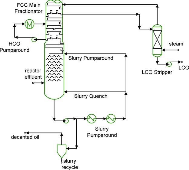
Figure 1 Base FCC Unit
The example shown is only part of the entire control system required. In this example, since no HCO product is made, any duty in the HCO pumparound shows up as HCO-slurry reflux liquid. The simple loops shown would be part of an entire unit multivariable optimizer. If no optimizer is present, other loops would be needed to make the system work correctly.
The purpose of a control system is to move disturbances from where they are more important to where they are less important. These control modifications do not make system disturbances go away. They shift it somewhere else. Typically, the disturbance is shifted to the product rates.
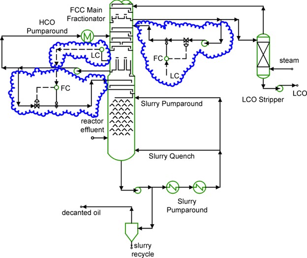
Figure 2 FCC Unit with total draws for improved LCO yield
The third approach is to add a decant oil stripper. Figure 3 shows this configuration. The stripper recovers LCO from the bottoms. The advantage of this configuration is that it has a minimal impact on the internal temperature profile inside the main fractionator. However, it does add vapor load to the main column and duty to the overhead condenser. Often the most significant issue is the increased duty on the main fractionator overhead.
The stripping can be a challenging service. If the slurry contains significant catalyst fines the stripper internals can easily plug and foul.
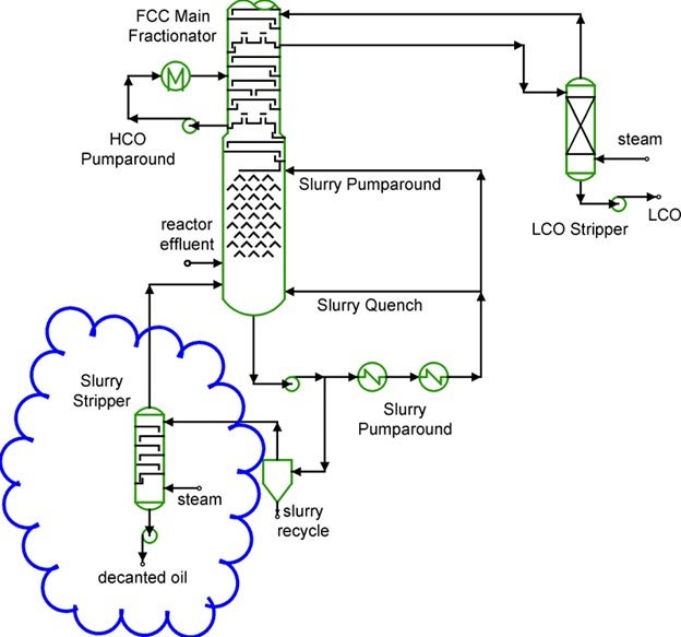
Figure 3 Slurry stripper to recover LCO
The options presented here are not the only possibilities. Nevertheless, the discussion covers the basic options and issues. Revamps must carefully balance yields, capacity, and product quality versus investment, reliability, and operating costs. Limits imposed by the unit configuration and equipment must be thoroughly understood to have a successful revamp that makes more LCO.
A team approach bringing in specialist resources with wide experience in practical applications at the very beginning of conceptual work will assure plants of success in FCC revamps.