Question 45: What are your typical consequences and probable sources of fuel gas fouling? What are your respective solutions?
LÉGARÉ (Andeavor Martinez Refinery)
I have the answers split up into three different sections in order of consequences, sources, and then solutions. I want to point out that this is like another throwback question; because in looking at the archives, I found that this topic goes back at least 20 years, if not 30 years. A lot of the answers back then still apply today, so I think we missed an opportunity for a throwback.
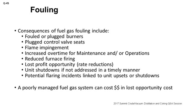
Consequences of fuel gas fouling include fouled or unplugged burners. We have seen plugged control valve seats. Flame impingement has resulted in increased overtime for Maintenance and Operations personnel. Maintenance folks are going to be the ones performing the burner cleaning, which usually increases overtime and operating expense cost. If Operators are responsible for burner maintenance, then it will fall on them.
Reduced furnace firing: As you start to plug your fuel system, you will be firing less; or, you will be trying to fire as hard as you can but transferring less heat to the process as a result. LPO (lost profit opportunity) kicks in if you have to cut rates because your fired duty went down.
Unit shutdowns: If they are not addressed properly, you will obviously have a worst-case scenario of an unplanned shutdown with the risk of associated flaring events. Potential flaring incidents linked to unit upsets or shutdowns are your worst-case scenario. The last situation we want to happen in California is to end up with a flaring incident. So, suffice to say, if you do not manage your burner system properly, it can cost the refiner a lot of money in LPO.

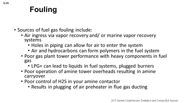
Sources: Where does all of this fouling originate? We have seen air ingress into the vapor recovery system as a source of oxygen that then reacts with hydrocarbons and forms polymers. Some of the system was half-buried as a result of poor inspection over time. This resulted in holes in the piping. The vapor recovery system works under vacuum, so air was pulled into the system. If you are not operating your gas plant properly, the splitters will not be splitting efficiently, and you will start to see C3s or C4s making their way into the fuel gas system until you start to find yourself with appreciable amounts of LPG (liquefied petroleum gas) in the fuel piping and burners.
Poor operation of your amine towers: From a stripping efficiency standpoint, you will have the risk of high H2S (hydrogen sulfide) in your fuel gas system and also amine carryover if the accumulator level is not maintained properly. Amine carryover into the fuel gas system has been a known source of fouling for some time. High amounts of H2S in the cooler portions of a heater’s flue gas train or on a boiler feed water economizer may experience ammonium bisulfite deposits and increased pressure drop in the flue gas system.

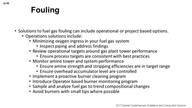
Solutions: I have solutions split up into two categories. One is the low-cost/no-cost operational projects. The second is the capital projects, such as minimizing oxygen ingress where you can start inspecting the system properly, identifying weak points or holes, and being either patching or replacing sections of pipe. The trouble there is that if you are going to start looking at replacing sections of your vapor recovery system, it has to be linked to major events like a turnaround where part of the refinery can be down, or work can be done during the cooler seasons at night when the breathing of the tanks is minimized.
Review gas plant tower performance to make sure that targets are set properly and that those targets are being discussed at Morning Turnover Meetings. Better target attainment on the stripping towers will ensure equipment operates as designed. Confirm the amine tower is meeting its performance objectives. Check the liquid level in the overhead accumulator to ensure that you are visually confirming that the transmitter is operating correctly. Sometimes, installing a coalescer downstream of the accumulator is a good idea if it has not been done already. Verify that the amine strength is in its targeted operating range. Make sure you are reading the Service reports from your amine supplier, because they tend to come in via email and contain valuable information on the quality of your amine.
Implement a proactive burner cleaning program. Instead of a reactive system that requires Maintenance to work on overtime, have an extra set of burners on hand that are already cleaned. This way, you will be looking at swap-outs, which is more efficient and quicker to implement. Also, you will get out of the embarrassing situation of having to explain to Management why you are having to cut rate to remove and clean burners when you could have purchased a few spare burners to have ready for installation.
Introduce an operator-based burner monitoring program. Have the operators inspect the inside of the firebox and notice what the flame patterns look like. In the Answer Book, I mention sending some of your key operators or maybe engineers to Oklahoma to a burner school, because there are some really good opportunities there for folks to get first-hand knowledge about what “good” looks like. They would then bring that information back to your plant. You may end up with a local SME (subject matter expert) or two out of it, so it is a good investment.
Ensure that you have a rigorous sampling program around your fuel gas systems so you can trend it over time. This is handy for looking at tower performance and how changes can impact fuel gas quality. For example, if you are coming out of a turnaround, you put your gas plant back online. When you see a step change in the fuel gas quality, you can potentially correlate it back to a startup of a tower. That helps with troubleshooting. Lastly, avoid burners with small tips if you know you have a problem with fuel gas plugging. Larger tips are going to directionally plug less often.

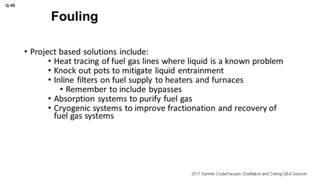
Now I want to talk about the more costly projects. What we have done is look at heat-tracing on systems, keeping heavier hydrocarbons in the vapor phase, and keeping material from condensing. Install knockout pots upstream of heaters to collect whatever liquid will drop out. Inline filters are also a good idea, but make sure you have the bypass in place so you can perform online cleaning of the filters. Installing an absorption system to purify fuel gas is a newer technology we are starting to consider, because it allows you to take out the sulfur, recover the LPGs, and cleanup your fuel gas system. Lastly, from my experience, cryogenic systems are also a potential solution. Although they are quite expensive, you also get to see the benefit of improved fractionation and recovery of hydrocarbons.

GAMBOA-ARIZPE (CITGO Refining & Chemicals, L.P.)
Eric’s answer is fairly complete. I will just add some minor comments. Again, the three-pronged nature of the question was consequences of the fuel gas fouling problem source, where they originate, and solutions. I just want to add a point about each.
Another consequence, based on the descriptions that Eric gave, is the flame length consideration for furnace burners. You can end up with process tube flame impingement if you do not clean the burner tips at an adequate frequency.
Here, we also recently started looking at the flare gas recovery system and found out that several of our refining neighbors were having a very similar corrosion problem to the particular problem we were experiencing. Upon some investigation, we discovered that oxygen incursion is a dramatic contaminant to the fuel gas system, particularly on the flare gas recovery line which ends up being routed to the fuel gas system. What oxygen does is lead to accelerated wet H2S corrosion mechanisms with very high hydrogen permeation rates.
What we observed was that oxygen incursion into the flare recovery system was creating corrosion rates as high as 200 mils per year; specifically on carbon steel piping and equipment. Accelerated growth of iron sulfide scale (the primary byproduct of wet-H2S corrosion mechanisms) can lead to not only hydraulic restrictions that back out the capacity of your flare gas recovery system, but also to containment problems with the line itself and to an increased risk for leaks. So, after much convincing, as well as after minimizing oxygen incursion into the flare header system wherever possible, a practical but pricey solution for managing the high corrosion rates observed in the flare gas recovery systems (promoted by oxygen) was to address it with an alloy upgrade, which we, at CITGO, were forced to do. Many of the vapor lines on the flare gas recovery systems tend to be very long. They are systems that are located close to the flare itself (which, themselves, are typically located far enough away from the process units); so, you are talking about a very long linear piping lengths.
PHILLIP NICCUM (KP Engineering, LP)
I researched this question a little when looking for something I did not find, so I have a question. Did any of you find any correlation between the olefin content and diolefin content in the fuel gas, such as propadiene being in the fuel gas and being a contributor to fouling within the fuel gas system? That had been my own experience, in particular on smaller orifices for purging pressure taps on FCC units.
LÉGARÉ (Andeavor Martinez Refinery)
My answer is no; but also, it is becoming increasingly important to us in the Bay Area. The local regulators are starting to look at fuel gas quality. It is one of the issues they want to regulate, in addition to what crudes we buy. So, we will start looking at this topic in more detail. We have folks assigned to do just that.
I want to address that last comment about Merox™ systems. What we have been doing in the last years is taking those Merox™ systems out of the flare system.
CHRIS STEVES (Norton Engineering Consultants, Inc.)
I agree with everything Eric said about the fouling, as well as with what Héctor added. Just also keep in mind that, many times, the fuel gas systems in refineries are very old – ridiculously old, in some cases – and that you are dealing with many of the sins of the past, in terms of the fouling. It would be great to keep low-orifice burner tips out of the heaters. But the regulators, as you know, are pushing more towards ultra low-NOx (nitrogen oxide) burners which have those very small tips. In many cases, if you have to go with ultra low-NOx burners, your only solutions will be adding filters or coalescers directly upstream of those particular heaters, and even looking at replacing the piping downstream of those new filters and coalescers with stainless steel to avoid corrosion issues.
GAMBOA-ARIZPE (CITGO Refining & Chemicals, L.P.)
I want to address other fuel gas quality points which are salient to this conversation. The gentleman asked about diolefins or olefins. Yes, they are known foulants. They tend to polymerize and cause problems related to the buildup of polymers, but there are other constituents that need monitoring. Most refiners tend to have some sort of online analyzer for their fuel gas, but it is supplemented by lab information, probably on the order of once or twice a day. The purpose of the lab analysis is to obtain the mercaptan information. Mercaptans, even in low concentrations (0-5 ppm) are corrosion promoters on the line. Again, a lot of these systems are carbon steel. So, it is just another consideration that you have to take into account.
ERIC LÉGARÉ (Andeavor Martinez Refinery)
Fuel gas fouling is not a new problem for refineries and has been covered in this forum for decades, literally. Consequences of fuel gas plugging include:
-
Plugged burners.
-
Erratic flame patterns.
-
Flame impingement.
-
Plugged control valve seats.
-
Increased overtime for Maintenance and/or Operations.
-
Reduced furnace firing.
-
Lost profit opportunity (rate reductions).
-
Unit shutdowns, if not addressed in a timely manner; and/or,
-
Potential flaring incidents linked to unit upsets or shutdowns.
In summary, a poorly managed refinery fuel system can easily lead to lost opportunity costs in the millions of dollars.
Sources would be:
-
Air ingress into your refinery fuel gas system, if there are holes on the vacuum side of the fuel gas system, including your marine vapor recovery (if applicable) or tank vapor recovery, as examples. Air ingress can occur in piping that is partial buried, poorly maintained, and/or partially submerged, leading to pitting corrosion and eventually air ingress. Oxygen and hydrocarbon can result in polymers formation, which will lead to plugged burner piping and/or burners.
-
Poor refinery gas plant tower operations could result in LPG+ in the fuel system, which could lead to burner fouling by coking of condensed hydrocarbons in your fuel system.
-
Poor control of H2S in your amine contactors could result in high levels of H2S in your fuel system. High amounts of H2S in the fuel system can result in fouling air preheaters or economizers in furnace ducting.
-
Poor operation of the amine contactor overhead system can result in carryover of amine into your fuel system. This problem has resulted in downstream fouling of the fuel system.
Solutions include:
-
Minimizing oxygen in your fuel system by sealing any holes on the vacuum side. This activity may require parts of the system to be taken offline or TAR opportunities when the system requirements will be minimized. Work with the Inspection Department to inspect existing piping for pitting. Have Maintenance ready to replace suspect sections of pipe if the system will be down.
-
Monitoring gas plant tower performance to ensure that the proper data points are being monitored and alarms are highlighted in Operations meetings.
-
To ensure that fuel gas quality is maintained, confirm that the amine system strength is in the target range specified by your supplier to ensure that H2S /CO2 is being absorbed. Lower H2S concentrations will help reduce fouling in the cooler sections of your furnace ducting.
-
Proactive burner monitoring and cleaning programs to move towards a proactive solution and not a reactive one. Have spare burners built, tested, and ready to swap out is preferred over having to cut unit rates while investigating reduced furnace firing.
-
Visual inspection of flame patters can indicate a fouling burner. Use third parties to help or send some engineers and/or Operations personnel to Oklahoma for burner school so they can help provide local troubleshooting.
-
Testing your fuel gas system on a regular basis can also help with trouble shooting as it may indicate a change in quality that could be a precursor to future fouling.
-
Monitor the amine contactors for potential carryover into the fuel system. Ensure that accumulator levels are kept low or look at installing a coalescer.
-
Burner tip sizing: avoiding burners with too-small tips that may lead to increased plugging.
Projects that help mitigate fuel system fouling include:
-
Heat-tracing on problematic fuel system piping can help heavier compounds stay in the gas phase.
-
KO pots can also be utilized, if warranted, with two-phase fuel gas systems.
-
Inline fuel gas filters upstream of each furnace. Ensure that bypasses with appropriate isolation valves are installed to allow for online cleaning.
-
Larger investments, such as solvent-based absorption, can help remove sulfur while recovering hydrocarbons. Cryogenic systems could also help improve fuel gas quality. High investment costs associated with these solutions usually require other economic or regulatory justification for investment to be justified.
RICHARD TODD (Norton Engineering Consultants, Inc.)
Fuel gas fouling in refineries is an ongoing problem and is typically the result of many years of corrosion due to moisture in the fuel gas system. These systems are typically saturated with water vapor due to the amine scrubbing that is used to remove H2S, and water may drop out as a liquid in low velocity areas or in areas with inadequate insulation. The largest problem associated with fouling of fuel gas systems is in the fouling of burner tips, many of which have become smaller with the move to ultra-low-NOx burners (ULNBs).
Many refiners who have heaters with new ULNBs installed have also tried to mitigate the impact of fouling on the tips by adding filter/coalescers to the fuel gas piping upstream of the heater to remove scale and liquid water, and then replacing the fuel gas piping with stainless steel from the coalescer to the burner to prevent corrosion downstream of the coalescer.
GREG SAVAGE (NALCO Champion)
Burner tip plugging preempts efficient burner operation and causes unit operators to fire the furnace with excess air to improve combustion. This process leads to poor furnace efficiency and greater energy costs, as well as possible throughput limitations. Plugging is often a result of either solids buildup – such as iron sulfide – from upstream corrosion or entrained aerosols from poor vapor liquid separation. Filtration and coalescers are typically used in fuel gas lines by most refiners to very effectively mitigate the issue. However, there are chemistries available to unplug burner tips and keep them clean; but caution must be exercised, as application methodology is critical to program success and minimizing fuel gas line corrosion from the use of these chemicals.
RAÚL ROMERO (NALCO Champion)
Fuel gas systems have different approaches regarding sources and applications. It is possible to find fuel gas configurations from a well-integrated and uniform composition fuel gas system to a very-segmented system with varying compositions, even within the same refinery. Therefore, fuel gas varies from dry, clean, relatively constant molecular weight streams to dirty, wet mixtures of process waste gases that can fluctuate significantly in composition and molecular weight. In the first case, the fuel should cause very few problems; but for the latter, safety and maintenance problems can occur unless the gas is thoroughly cleaned and dried. Both inorganic and organic sources – such as iron oxide, iron sulfide, and polymers – can plug fuel ports in the burner gun, thus restricting burner capacity and causing poor combustion and possible flame impingement. Some burner designs – like staged fuel low NOx – are particularly susceptible to fuel orifice blockages due to the very small sizes necessary to provide the fuel staging.
To protect against wet or dirty gas, knockout drums are a minimum requirement for all fuel gas systems. However, in some instances where the fuel is very dirty or wet, more efficient gas cleaning equipment – such as coalescing filters – should be specified downstream of the knockout drum if liquid and solid particulate removal is required.
Knockout (KO) drums should be located as close to the heater as allowed. The intent of the knockout drum is to provide an opportunity for vapor to condense; therefore, it and piping supplying gas should not be heat-traced. Piping downstream of the knockout facilities should be steam-traced, insulated, and drained if condensation of the gas is possible (inclined to the KO drum).
Fuel gases from the FCCU and DCU processes can have higher olefin content, increasing potential for polymerization if heat-traced piping is in use. Increasing the fuel gas mixture to have a more uniform composition mitigates the effect of composition variation from different sources. Special attention should be given to the fuel gas system with the potential for high H2 concentration since tip material must be reviewed to avoid high temperature and oxidation deterioration process.