Question 41: What are the considerations you use for extending hydrogen plant catalyst life cycles (i.e., lower production rates, furnace tube failure, etc.)?
BRIGHT HOLLAND (Haldor Topsoe, Inc.)
There are many parameters affecting the hydrogen plant catalyst life cycles, such as lower production rates, furnace tube failure, unplanned plant shutdowns, larger catalyst volumes, elevated energy consumption, and finite ZnO/S (zinc oxide/sulfur) capacity.
Lower Production Rates will obviously result in longer catalyst lifetime due to a lower gas velocity over the catalyst. However, a hydrogen plant operating with older catalysts will have higher a CH4(methane) slip from the steam methane reformer (SMR) and higher CO slips from the high temperature shift (HTS) and low temperature shift (LTS) reactors because of catalyst deactivation due to sintering and poisoning. For example, as SMR catalyst ages, it experiences a gradual and unavoidable decline in activity due to thermal sintering, and in some cases, sulfur poisoning. As a result, a higher S/C (steam-to-carbon) ratio or higher reformer outlet temperature is required to keep the temperature approach to equilibrium (ATE) for the reforming reaction low and maintain an acceptable CH4leakage. Both adjustments require a higher heat input from the reformer burners, which would cause higher tubewall temperatures (TWTs). However, if the TWTs are already near the maximum design temperature, the heat input cannot be increased further. In that situation, plants must decide between replacing the SMR catalyst charge, lowering the H2(hydrogen) production rate, and tolerating a higher CH4leakage (and its associated lower H2product purity).
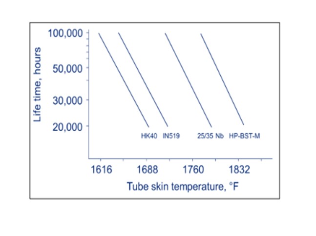
Furnace Tube Failure: Furnace tubes lifetimes are strongly dependent on the TWTs. TWTs should be kept below the maximum design temperature to minimize the risk of cracks in tubes and achieve the tube design life of 100,000 hours. Operating at 40°F above the design TWT will decrease tube life by 50%; and when operating at 200°F above design TWT, tubes could rupture at any time. Reformer tubes are expensive and often require long lead times, making damaged tubes very costly and time-consuming to replace. A complete furnace re-tubing can cost several million dollars.
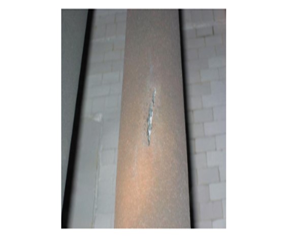
After a number of years in operation, normal thermal aging of the furnace tubes can result in the development of isolated cracks or ruptures in the tubewalls. A crack allows the process gas in the tube to leak out into the fireboxwhere it combusts immediately and can cause significant damage to the surrounding tubes. If the flame is directed towards another tube and causes a hot spot, the other tube could quickly fail due to overheating; so the plant should be taken offline immediately. The ruptured tube may be taken out of service by blinding the inlet and outlet pigtails.
The overheating incidents can be eliminated by installing Topsoe Furnace Manager (TFM) on your furnace. Please refer to our response to Question 2.
Unplanned Plant Shutdowns: Catalyst changeouts should be scheduled to coincide with planned shutdowns so that there never has to be a plant shutdown for the sole purpose of replacing a catalyst charge. If a catalyst charge is not quite at its end-of-run when a plant turnaround occurs, it is typically more cost-effective to replace the catalyst prematurely than run the risk of catalyst replacement being required mid-turnaround cycle on an unplanned or emergency shutdown. This economic benefit is because the cost of a new catalyst charge is much lower than the cost of several days of lost production during plant downtime.
Larger Catalyst Volumes: For most of the hydrogen plant reactors, installing larger catalyst volumes will result in longer catalyst life cycles. The higher catalyst volume corresponds to a lower space velocity for a given feed rate; however, increasing the catalyst volumes may not be possible for many reactors.
The disadvantages of a larger catalyst volume are a higher pressure drop across the bed and more expensive catalyst replacement costs if there is a plant upset that requires a catalyst charge to be replaced unexpectedly before it reaches its end-of-run. Some scenarios when this could occur include an upstream boiler leak or poisoning causing accelerated deactivation of the HTS or LTS catalyst, iron carbide formation across the HTS catalyst during accidental operation at a low S/C ratio, or sulfur poisoning of the SMR catalyst if the feed purification section catalysts are not replaced at the correct times.
Elevated Energy Consumption: As SMR catalyst ages, the plant S/C ratio and/or the SMR outlet temperature must be increased to maintain an acceptable CH4leakage. The extra fuel consumption necessary to heat additional steam or achieve a higher outlet temperature in the furnace can easily be calculated and translated into a dollar value. Knowing the additional fuel cost required to operate an aging SMR catalyst charge for an extra plant turnaround cycle can help determine the most cost-effective time to replace the catalyst.
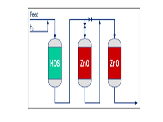
Finite ZnO Sulfur Capacity: Zinc oxide absorbents remove H2S from the plant feed via the following reaction: ZnO + H2⇆ZnS + H2O. Since ZnO is consumed by the reaction, a charge of desulfurization absorbent can only absorb a fixed amount of H2S before becoming fully saturated with ZnS. Therefore, end-of-run for a ZnO charge is easily defined as the start of sulfur breakthrough. Once the ZnO is fully saturated, the sulfur slip will start to increase rapidly; so continuing to operate without replacing the charge will allow sulfur to poison downstream catalysts. Sulfur poisoning is especially harmful to the SMR and LTS catalysts, which are much more expensive, time-consuming, and labor-intensive to replace than the ZnO absorbent. Therefore, if the desulfurization absorbent reaches end-of-run between plant turnarounds, it may be economically justifiable to have an unplanned plant shutdown to replace the ZnO absorbent material.
Alternatively, the risk of a costly, impromptu shutdown can be avoided by using two desulfurization reactors in series with bypasses around each that allow the ZnO absorbent in one of the reactors to be replaced while the plant continues to run using the other desulfurizer.
PAT BERNHAGEN (Amec Foster Wheeler)
We have designed and supplied what the industry calls high flux reformer designs (top-fired and cylindrical reformers) and the low flux designs (Terrace Wall™ and side-fired reformers). The catalyst sensitivity to life cycles is dependent on the type of design. High flux designs are based on co-current flue gas and process flow. The concept is to rapidly increase the process temperature to start the reaction. This design, therefore, has very high fluxes and tube metal temperatures near the inlet of the process. Any catalyst poisons or heavy hydrocarbon carryover can cause catalyst life loss or coking. An additional design feature is a ‘continuous’ high wall temperature down the catalyst tube, which impacts the catalyst life. Extending catalyst life requires continuous monitoring of burner flames to prevent impact on the tubes and maintaining drafting through the unit with the ID (inner diameter) fan.
The Terrace Wall™ reformer is classified as a low flux design. It is a thermally efficient counter-current design with upwardly fired burners. With the counter-current design, the catalyst is heated more linearly from inlet to outlet; and where the poisons and/or heavy hydrocarbon react, the temperature profile is low that it does not cause higher-than-design tube metal temperatures. Any loss of catalyst life near the inlet just moves the reaction further down the tube. Only near the outlet is the catalyst subjected to high operating temperatures. This gradual and predictable temperature profile along the catalyst tube and catalyst itself provides extended catalyst life as compared to high flux designs. This extension can be useful for long runs or higher operating capacities. The burners are stabilized on target walls and fire upward, so monitoring is mainly to fire each burner evenly.
JIM FLESHMAN (Arivegry LLC)
In addition to the continuous decay of catalyst performance, which can be tracked and largely predicted, be aware of system upsets over the entire life of the catalyst. These upsets can have an outsize impact on catalyst life. They may involve reformer temperature excursions, poisoning, or liquid contamination. The impact of the resulting catalyst damage may not be obvious. For example, carbon formation tends to be heaviest partway down the tubes. Since this is not the hottest part of the tube, an increase in temperature due to mild coking may be overlooked. Combination of upsets and slow buildup of poisons or fouling results in a loss of activity, in turn making the catalyst more sensitive to changes in operating conditions. The aged catalyst may not want to “come back” after a shutdown or trip. Catalyst life can be extended by treating the feedstock to remove traces of sulfur or other catalyst poisons, careful and steady control of steam/carbon ratio to avoid carbon formation on the catalyst, and/or avoiding physical shocks to the catalyst due to temperature cycling or carryover of liquids from the steam drum.
SUSAN SIMPSON (Johnson Matthey)
Monitoring is critical to the extension of catalyst life cycles in the hydrogen plant. The catalyst supplier can be a key resource in this monitoring as they have the tools, process knowledge, and onsite services to assess the risk that could be encountered when extending catalyst life. Each of the catalytic units in a typical hydrogen flow sheet should be considered.
Purification
The hydro desulfurizer is generally limited in life by pressure drop growth with lighter feeds, such as natural gas and refinery off-gas. Fouling of the catalyst can occur due to carryover of debris with the feed. If the inert hold-down material is omitted or inaccurately sized, the catalyst can move, generating fines that can increase pressure drop. Tracking pressure drop normalized by flow is a useful tool to estimate catalyst life. The use of a trilobed-shaped absorbent can minimize catalyst changeout frequency by enhancing voidage and offering low pressure drop. In addition, it supplies higher activity and increased strength compared to other shapes.
The desulfurizers are limited by the sulfur capacity of the absorbents. The absorbent’s performance can be monitored by recording the inlet and exit sulfur levels and gas flow rate at frequent intervals during its life. The total sulfur content absorbed by the bed can be calculated and compared with the expected pickup of the absorbent, thereby giving an estimate of the unused proportion of the bed. A flow sheet with two vessels in lead/lag positioning can also allow operation to higher sulfur capacity levels and the extension of catalyst life. Finally, layering a high sulfur capacity product in the majority of the bed with a sharp mass transfer zone product at the bed outlet can also extend the purification bed life.
Ultra purification or sulfur polishing absorbents are appropriate in plant circumstances where the downstream catalysts are more susceptible to poisoning even by low sulfur levels, such as pre-reforming catalyst. In addition, ultra purification products help extend the life of steam reforming catalysts in highly stressed reforming duties. The aim of the ultra-purification stage is to lower the level of sulfur slip to less than 10 ppbv (parts per billion by volume) total.
Reformer
In the reformer, end of catalyst life is generally determined by catalyst poisons, carbon formation, and thermal aging. Loss of activity through poisoning by contaminants in the process gas can cause carbon formation. Carbon forms when the hydrogen level is too low to prevent the cracking reaction. The process gas temperature increases allowing the rate of cracking to become significant. Causes for carbon formation include catalyst deactivation, low steam-to-carbon ratio, heavier feed, and flame impingement. In addition, the gradual loss of activity or thermal aging caused by loss of nickel surface area through sintering places a limit on the life of a catalyst charge. This effect is highly dependent on the operating conditions.
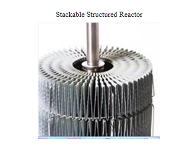
Proper catalyst selection can help avoid these scenarios. The use of a quadralope-shaped catalyst provides a 17% improvement in geometric surface area resulting in low methane slip and an approach to a response to an AFPM 2016 Q&A Hydroprocessing question regarding equilibrium throughout the catalyst life. In addition, a low start-of-run pressure drop and less pressure drop buildup are attributed to the quadralope shape. Furthermore, the use of a promoted catalyst increases the rate of carbon gasification resulting in higher carbon margins and extended catalyst lives. Newer developments in catalysts, such as structured catalysts, result in even higher surface area, improved heat transfer, and lower pressure drops. These advancements help avoid carbon formation and pelletdegradation resulting in longer life.
In addition to catalyst selection, careful monitoring can reduce the risk of extending catalyst life. Methane slip is a good indicator of catalyst activity. Increased pressure drop can be an indicator of carbon formation or catalyst breakage due to thermal cycling. Carefully monitoring of tubewall temperatures (TWT) can also indicate catalyst performance.
Two of the main methods to measure tubewall temperatures in steam reformers are listed below.
1.Infrared (IR) Pyrometer: The most common way of measuring steam reformer tubewall temperatures is to use a hand-held infrared pyrometer. This approach can provide a reliable measurement method when the temperatures can be corrected for the effects of background radiation and emissivity.
2.Contact Thermocouple (Gold Cup Pyrometer): The contact thermocouple, referred to as a "gold cup pyrometer", is a specialized piece of equipment used to measure the surface temperatures of tubes that are accessible from the peep holes. Comparison with data from an infrared pyrometer can then be used to infer the emissivity; and hence, calibrate the IR pyrometer for future use.
Reformer Imager
A new method for measuring tubewall temperatures is the reformer imager. This camera takes reliable video images through the peepholes. The corrected temperatures yield very similar results to the pyrometer and gold cup methods. Images are recorded and can be stored for future reference. This is a unique advantage over other temperature measurement techniques. In addition, the reformer imager allows the TWT measurement of most all tubes in the furnace from top to bottom.
In addition to measuring tubewall temperatures, CatTrackers® are a tool used to measure the actual process gas temperature within the tube itself. This multi-point thermocouple provides an accurate temperature profile and exit temperature of the reformer tube. It provides continuous real-time monitoring during operations and transient conditions when traditional thermocouples can lag behind. This allows operators to respond rapidly to operational changes minimizing their effects and extending catalyst life. CatTracker® data can also validate a simulation model. The model can in turn be used to project catalyst performance with age and to evaluate changes in operating conditions, such as steam to carbon ratio or feed rates, to determine their effect on extending catalyst life.
Shift
High temperature shift (HTS) catalysts are normally very robust and generally any poisoning in the plant is likely to be evident in the steam reformer before affecting the HTS. However, HTS catalyst activity will be affected by physical foulants that blocks the gas from effectively reaching the active catalyst sites. The most common cause is boiler leaks. There are a number of steps that can be taken to reduce pressure drop. These include four optional methods.
1.Use a larger particle size. Modern HTS catalyst have been formulated with a structural promoter to improve diffusion through the pellets, which means that the same CO conversion can be achieved in larger catalyst pellets because the effects of diffusion have been lowered.
2.Use a shaped catalyst. HTS catalyst with an optimized shape decreases pressure drop and improves conversion with increased geometric surface area. The enhanced voidage increases the resilience to fouling.
3.Improve the catalyst support and gas collection systems. Studies have shown that there can be significant pressure drop in the support and collection system under the catalyst bed. Redesigning and modifying gas collectors can address this issue.
4.Optimizethe inlet temperature to affect catalyst life. At start-of-run, a lower inlet temperature might be optimal to minimize CO slip as the system is equilibrium limited. However at end-of-run, the system is kinetically limited and a higher inlet temperature is favored. There is often a concern that raising the temperature of the HTS catalyst will increase the rate of thermal deactivation of the catalyst resulting in a shortened overall catalyst life. However, lives exceeding sixyears are achieved with modern HTS catalysts that exhibit improved strength and robustness.