Question 30: What are common mechanical defects that occur to the weld overlay material in hydroprocessing reactors? What are the most common locations for defects, and does the location play a factor in the mechanical integrity of the equipment? How do you detect and repair the defects? How often do you conduct Remaining Life Analysis (RLA) and/or Fit For Service (FFS) Assessment on critical equipment?
AL-FUDHAIL (Saudi Aramco)
As you can see, and as Gordon has mentioned quite eloquently, this is quite a hefty question; so, bear with me to get through the answer.
A lot of my answers are based on actual experience with one of our existing units. It is a vintage unit designed in 1977 and commissioned in 1982. It is a single-stage unit with liquid recycle, two parallel chain configurations, and four reactors in series in each train. The reactors have now been in service for over 35 years. Due to aging of the reactor, in 2009 we discovered signs of overlay disbanding that eventually propagated to cracks in a few locations and required a patch repair.
Now the first question is: What are common mechanical defects that occur to the weld overlay material in hydroprocessing reactors? First, microstructure changes or sigma-phase embrittlement. This damage can occur either during original fabrication and post-weld heat treatment or during operation. Therefore, the weld overlay conditions during a fabrication govern the susceptibility to hydrogen disbonding. Higher traveling speeds and welding currents result in good resistance as they generate fine microstructure without, of course, planter grains at the interface. Therefore, the fabrication stage is a crucial step and requires dedicated attention to avoid inherent damage.
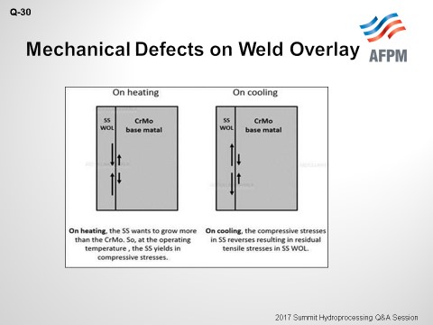
Second, low cycle fatigue cracking thermal grading during startup and shutdown cycles: Thermal stresses and residual hydrogen concentration drive weld overlay cracking, as well as the disbonding mechanism, i.e., cracking along weld overlay, which is a chrome-moly-based metal interface. During heating and cooling cycles, the coefficient of thermal expansion mismatch between the stainless-steel weld overlay and base metal generates excessive stresses at the interface for an embrittled transition layer. This cycling of temperatures aggravates the situation, as you can see shown on the slide.
Third, weld overlay disbonding: High concentration of hydrogen remains in the reactor even after shutdown. Such hydrogen – in excess of 4 ppm – at ambient temperature is considered beyond equilibrium concentration and can cause hydrogen embrittlement of transition zone, which is the more sensitive zone. Hydrogen disbonding is purely a hydrogen distribution issue. The best way to slow down this problem is to control the amount of hydrogen dissolved in the weld overlay and base metal. This resolution can be achieved by utilizing a lower operating temperature, lower operating pressure, and smooth shutdown procedure. Also, the microstructure at the interface – being a primary factor – can be improved to govern the resistance to disbonding.
Fourth and not least is the synthetization of non-stabilized dust in stainless steel. Almost all non-stabilized stainless steel gets sensitized – either during fabrication or during service, leading to loss of its corrosion resistance to hydrogen and H2S attack. This loss of sensitivity will also make overlay susceptible to polythionic acid or chloride stress corrosion cracking. Therefore, NACE requires washing all stainless-steel surfaces in reactors – especially the ones that are non-stabilized or sensitized in reactor circuit – with an alkaline solution to neutralize against such hazards during outages.
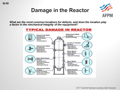
The second question is: What are the most common locations for defects, and does the location play a factor in the mechanical integrity of the equipment? As you can see on the slide, the most critical areas where damage can occur are at structure welds. These areas require periodic inspection of specific parts of the equipment such as hands-to-shell junction, nozzle details, internal supports, and skirted vessel joints. Finding a defect in these areas can affect the mechanical integrity of the equipment.
Third: How are the defects detected and repaired? Defects are detected via periodic inspection using several techniques. Acoustic emission testing (AET) is a qualitative technique that can detect small-scale damage during pressurization, depressurization, and/or plant operation. The benefit of AET is that it can optimize subsequent inspection with NDE (non-destructive examination) focused on locations of high signal intensities that are identified by the acoustic emission prior to shut down. Second, automatic ultrasonic testing techniques include external C-scan and mapping of the shell to detect internal damage. Third, the time-of-flight diffraction technique is used to detect and measure macrocracks, preferably UT (ultrasonic testing) if crack sizes are needed for Fit For Service assessment or remaining life calculations. Fourth is your basic institute of metallographic replication to detect microcracks. Fifth, the conventional technique: straight-beam UT (ultrasonic thickness), MT (magnetic particle inspection), or PT (dye penetrant testing) for internal/external surface inspection. These tests are all used to detect macrocracks. As for the repairs, in the past we have utilized the original reactor manufacturer to develop patch repairs for the defects.
Last but not least: How often do refiners conduct Remaining Life Analysis and/or Fit For Service on critical equipment, Remaining Life Analysis or Fit For Service Assessment are normally based on inspection findings about the state of the reactors, such as cracks or base metal corrosion. The assessment is done by calculation based on inspection data, material of construction, data of components, and historical operating data of the equipment. For aged or vintage designs, CRIP (Research Center in Pulp/Paper Engineering) evaluation may be required if operating above 800°F for chrome-moly steels. Thank you.
LONG (HollyFrontier Corp - Navajo)
Noaman did a good job answering this question, so I will just try to highlight some of our experiences. We have not experienced these mechanical defects on weld overlay material in hydroprocessing reactors in recent history. We have experienced more issues with regard to fabrication defects.
MARK MUCEK (Honeywell UOP)
The common mechanical defects that occur are disbonding and cracking. Non-vanadium-modified 2¼ Cr-1 Mo material is more susceptible to disbonding than vanadium-modified 2¼ Cr-1 Mo-V material. V-modified 2¼ Cr-1 Mo has a much higher solubility of hydrogen compared to conventional 2¼ Cr -1 Mo.
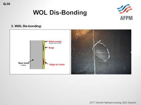
Disbonding occurs at the interface between the weld overlay and the base metal substrate. There have also been instances of cracking between the weld overlay beads due to incomplete slag removal. Another potential situation would be if the cracks spread or propagate into what are called “spider cracks”. If the cracks are down to the overlay/base metal interface, the concern is that the process fluid can come in contact with the Cr-Mo (chrome-molybdenum) base metal and cause significant corrosion, which will undermine the weld overlay and create a larger problem. If the cracks propagate through the overlay and into the Cr-Mo base metal, which is not necessarily common, a situation may develop that could cause the crack to propagate into and through the base metal, resulting in a leak to the atmosphere.
Disbonding is usually found visually when a slight bulge is noticed in the overlay. Cracks may also be determined visually or with Penetrating Testing if there is a suspect area. Disbonding is typically monitored rather than repaired. If the disbonded area or the bulge in the overlay get too large, or if there are multiple disbanded areas, the reactor is often replaced. Disbonded overlays have been repaired, but these repairs do require a local post-weld heat treatment (PWHT). If the affected area is substantial, conducting a PWHT becomes impractical.
Some of the industry Best Practices and repair techniques are:
-
If the cracks are very shallow, they can be ground to extinction and the area monitored at each unit turnaround.
-
If the cracks are slightly deeper but do not penetrate to the base metal interface, it may be possible to do a weld repair without a PWHT. In order to accomplish this repair, a full-size weld mockup needs to be made and a weld procedure developed. A cross-section of the mockup must be polished and examined. Optical metallography and hardness testing of the Cr-Mo base metal must demonstrate that the weld procedure results in a repair that does not cause a heat-affected zone in the Cr-Mo base metal.
-
If the cracks propagate to the interface with the base metal after grinding the cracks out, one of two methods are typically employed.
-
A stainless-steel patch is placed over the ground area and fillet-welded to the intact weld overlay. The patch may or may not have refractory material placed in the gap. This type of repair must be inspected at every turnaround to ensure that the fillet welds are not cracked.
-
The weld overlay is restored, and the area is given a local PWHT.
-
If the cracks propagate into the base metal, these cracks must be ground to extinction. The excavation in the Cr-Mo (chrome-molybdenum) base metal is restored with matching filler metal, followed by restoration of the weld overlay. The repair must then receive post-weld heat treatment. Alternatively, the reactor can be replaced.
W. BRYANT DUNCAN (Honeywell UOP)
How often you conduct Remaining Life Analysis (RLA) and Fitness For Service (FFS) evaluations is a hard question to answer for any one specific refiner. The equipment design is based on expected operating conditions such as pressure, temperature, fatigue cycles, and corrosion rates. The reality is that this critical equipment is not always operated per design. Operating circumstances, operating performance, feed makeup, unit excursions, and manufacturer quality will all have an impact on the remaining life and Fitness For Service details associated with all pressure-containing equipment.
The type of inspections performed during the life of the equipment, either onstream and/or during planned maintenance events, will dictate the next inspection intervals, the remaining life of the equipment, and whether the equipment is fit for service. The information gathered during these inspections/testing events will be utilized in any considerations related to useful life of critical equipment. Critical data collected over time should be utilized to either validate the design life of the equipment or correct the projected damage progression rates in the design of the equipment. This information could also be utilized to give you corrosion rates (short- or long-term), next required inspection dates, and/or anticipated repair or replacement dates, or the data could be used when making repair or operational decisions to safely operate the equipment.
The following are only a few of the codes or recommended industry Best Practices that could be considered in the type of inspection, testing, and methods considered when determining or affecting remaining life and/or fitness for service. Keep in mind that there may be requirements, above and beyond those listed here, which are driven by jurisdictional considerations, owner/operator internal procedures, or the owner/operator insurer.
-
API 510 Pressure Vessel Inspection Code: In-Service Inspection, Rating, Repair, and Alteration
-
API 570 Piping Inspection Code: In-Service Inspection, Rating, Repair, and Alteration of Piping Systems
-
API 653 Tank Inspection, Repair, Alteration, and Reconstruction
-
API 571 Damage Mechanisms Affecting Fixed Equipment in the Refining Industry
-
API RP 572 Inspection Practices for Pressure Vessels
-
API RP 573 Inspection of Fired Boilers and Heaters
-
API RP 574 Inspection Practices for Piping System Components
-
API RP 579 Fitness-for-Service
-
API RP 580 Risk-Based Inspection
-
API RP 581 Risk-Based Inspection Methodology
-
API RP 584 Integrity Operating Windows