Question 28: Our hydrotreating unit continues to suffer from pressure drop issues. Multiple graded-bed schemes have provided incremental improvements. What other successful solutions to further mitigate pressure drop buildup do you employ?
PETER BENDTSEN (Haldor Topsoe, Inc.)
Solving reactor pressure drop issues has been a decades-long ongoing effort, and Haldor Topsoe has been a pioneer within this area since the early 80s when Haldor Topsoe first commercialized highly effective catalytically active grading products.
Grading and Chemical Injection
Expanding the grading system will directionally improve onstream time before a unit reaches its pressure drop limitation; and by simply increasing the volume allotted for grading, you will proportionally increase the storage volume for particulates introduced with the feed and/or for storing polymerization products formed from the reactions of very reactive feed species, such as olefins and, in particular, diolefins. However, this process may not always extend the cycle length proportionally for a number of reasons. The key lies in thoroughly studying the pressure drop formation mechanism and engineering a solution that addresses the underlying cause(s).
An example where expanding the volume of the grading system may fall short of expectations is with NHT (naphtha hydrotreater) units that experience drypoint in the furnace or with NHT units that process coker and FCC naphthas. In these situations, flakes of coke spall from the furnace tubes and are carried to the top of the catalyst bed with the process stream, where these flakes/chunks plug the very top part of the catalyst bed, independent to how much grading or hold-down materials installed. One obvious remedy is good monitoring of the drypoint and operating the unit such that drypoint happens in the upstream heat exchangers. This monitoring often means overtreating, with respect to the product specifications on sulfur and nitrogen, for example, at SOR, but it does allow for an overall longer cycle length of the unit.
Another example are units that process feeds containing oxygen and/or diolefins where polymerization occurs in the preheat train, which may also lead to pressure drop problems, as these reaction products enter the reactor overtime. Here the remedies include good nitrogen blanketing of tanks, the use of oxygen scavengers (chemical injection), and diolefin saturation reactors.
Depending on the nature of the pressure drop problem, other chemical injections may be helpful in a given scenario. There are dispersants available for carbonaceous-driven pressure drop problems; and if a pressure drop problem has already manifested as a result of corrosion (Fe)-based products, then injecting a coagulant may help reduce the pressure drop problem and allow a unit to operate until its EOR date. There are a number of precautions that need to be taken when using chemical injectants, and the chemical supplier can offer advice on this.
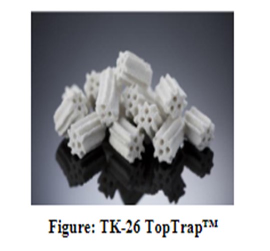
TK-26 TopTrap™
To handle particulates introduced with the feed, in particular inorganic iron, HaldorTopsoe launched the microporous particulate trap called TK-26TopTrap™, which is an industry-leading trap material.TK-26TopTrap™ is manufactured in an optimized multi-lobe shape with three axial holes to provide about 20% higher pickup capacity as compared to its industry-provenpredecessor,TK-25TopTrap™.TK-26TopTrap™is designed to give a 61% particle void fraction, in addition to a large internal pore volume, as a result of its macropore system.
Larger sized inorganic contaminants deposit in the spaces between the particles; fine or smaller sized materials enter the pore system and are trapped within the structure of the particle itself (see figure below). The internal void of TK-26TopTrap™is 25%, so that the total void in this product is greater than 85%.
Operational Changes to Extend Cycle Length
In the situation described above where a pressure drop problem has already developed, there are some operational moves that can be made to ease the pressure drop problem and help extend cycle length to the planned EOR date. One effective option is to gradually reduce the recycle gas rate and run closer to unit dP limit (dictated by outlet collector, bed support). While reducing the recycle gas compressor rate may be effective in lowering the reactor pressure drop, it will increase the coke fouling /deactivation rate of the catalyst system. If the catalyst is determined to be removed at shutdown and has sufficient catalyst activity, this process revision is one viable option which can be applied in commercial operation. Another option is to perform an LCO flush and/or a hot hydrogen strip. Haldor Topsoe can supply recommended procedures for these two scenarios.
Technology Solutions
Feed Filtering
One option is to reduce the filter sizes / openings in existing feed filters and accept more frequent replacements, cleanings, and backwashes. If a unit is not already fitted with a feed filter, this may, in many cases, prove costly or difficult due to plot space, etc. In addition, there are new procedures to be adopted with feed filter cleaning/exchanges.
Scale Catcher
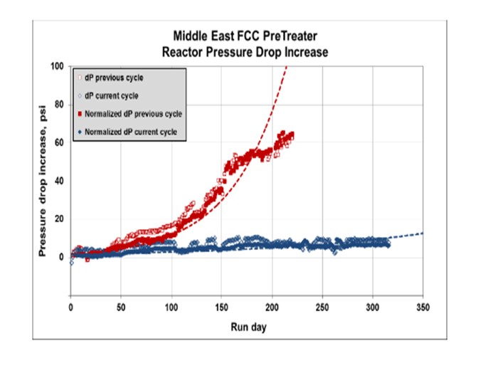
Haldor Topsoe offers highly effective scale catcher technology for both vapor-only (naphtha hydrotreaters) and mixed-phase (trickle-bed hydrotreaters). A scale catcher is an engineered mechanical device that is installed in the top of the reactor in the head space above the top tangent line and above the distribution tray. This technology can be easily adopted into existing unit configuration schemes, and the cost is typically very low compared to the return including significant extensions in cycle length, often more than doubling cycle lengths for units limited on pressure drop.
The plot below shows the successful installation of a Haldor Topsoe mixed-phase scale catcher in an FCCPT in the Middle East, where pressure drop issues have been eliminated after the installation of the scale catcher.
For more information on Haldor Topsoe Scale Catcher Technology, please refer to Haldor Topsoe’s answer to Question 8.
CHRIS CLAESEN (Nalco Champion)
First, the root cause needs to be determined. If the dP is caused by corrosion products due to corrosion in the upstream refinery units, the corrosion in these units can be reduced by applying the proper corrosion control program. If the dP is caused by gum formation, the gum formation needs to be controlled by applying a program in the feed and storage system. For resid hydrotreaters, dP often is caused by solids and metals in the desalted crude; some of these can be reduced by applying a removal program in the desalter stage. While we recommend that the focus should be on prevention measures, we have successfully reduced hydrotreater dP on many units by applying an online cleaning program.
PATRICK GRIPKA (Criterion Catalysts & Technologies)
Pressure drop issues can be difficult to solve, but the number of units with severe and chronic delta pressure (dP) issues have been significantly reduced over the last 15 to 20 years due to the time and effort spent in understanding the root causes of a particular unit’s dP issues by testing and sampling of the spent catalysts, followed by:
*Improved feed filtration,
*Feedstock management,
*Use of catalyst grading systems that provide size and activity grading, and/or
*Use of specialized hardware like scale catching trays and filter trays.
No matter what your underlying cause of dP –for example, feed filtration, equipment fouling resulting in Rx fouling, corrosion products fouling, salt deposition, etc., filter trays will always help the issue. In the simplest sense, filter trays increase the surface area available for contaminant deposition without reducing overall catalyst volume.
Our sister company, Shell Global Solutions, has filter and scale catching tray elements installed in over 100 vessels. The first filter tray design was installed in 1991; the first scale catching tray, in 1997. Shell is currently on the fourth generation of improvements on these technologies as we continually innovate and learn from the performance of this hardware in vessels in our Shell and Joint Venture refineries, which we own and operate, and in customer refineries that we service.
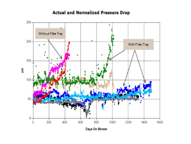
I want to share a couple examples of situation with which I have personally been involved and which convinced me of the value filter trays can provide. The first example is an FCCPT unit processing vacuum gas oils, coker naphtha, and heavy coker gas oil. This unit historically had 12-to14-month cycles, as you can see from the graph below, on cycles marked “without filter tray”. The first cycle after the filter tray (green and brown data) was significantly longer but was shut down on dP due to compressor salting issues. The two subsequent cycles (light and dark blue, black and gray data) were about four years long. These cycles ended on activity,not dP. A great success story! A filter tray has completely alleviated the short cycle shutdowns due to dP.
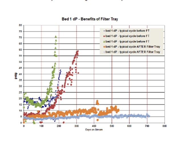
In another example, a unit had multiple very short cycles (six to 10 months; shown in green, blue, and red in the graphs below) due to significant corrosion products that caused dP issues in Bed 1. Grading schemes were improved from cycle to cycle using all possible sizes and types of grading with very little improvement in cycle length observed. The amount of foulant was just too large to be handled by grading alone. The cycles after filter tray install (orange and light blue) were much longer (18 months and 22 months). And the cycles after the filter tray was installed were shut down due to activity and not dP. A great success story!
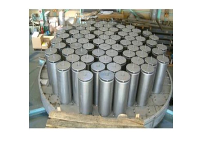
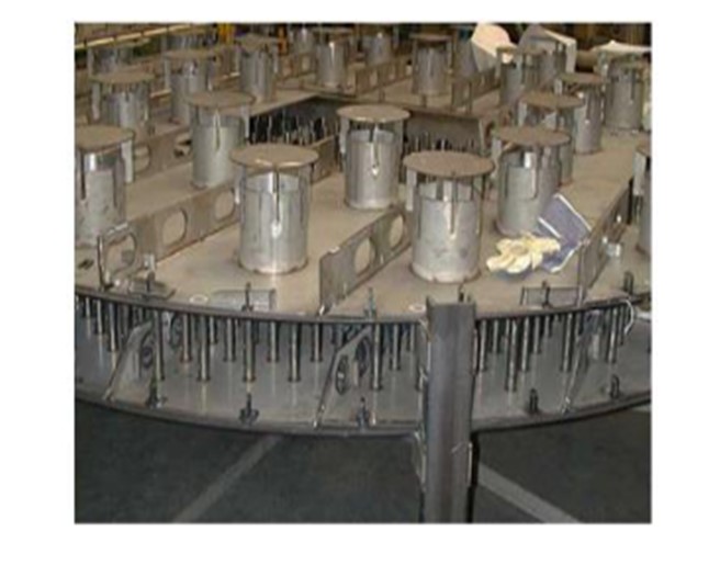
A Shell filter tray provides chemical and physical fouling abatement, and each of the filter elements on the filter tray is in the top head of the reactor so active catalyst volume amounts are notreduced. The filter elements are typically filled with the smallest size of catalyst in the reactor (e.g., 1.3 mm preferred). The figure below gives a picture of an assembly. The technology is continually being improved. One of the latest developments is to fill one of the filter elements on the filter tray with grading layers and leave the top open so the feed can run directly through. This technique allows for a quick grading evaluation upon opening the reactor.
A scale catching tray is used for physical fouling abatement and scale trapping. Typically, these are used in reactors which are operating in vapor phase or where the particulates are very large (i.e., scale). These trays also sit above the distribution tray in the top head of the reactor.
Repeated cycles with dP issues should not be allowed to continue. There are good, proven solutions to use if feedstock management and grading improvements are not sufficient to resolve the issue.
DENNIS HAYES (Nalco Champion)
Depending on the type of foulant that is causing the pressure drop, a selection of antioxidant or dispersant or combination may reduce the quantity of material that is promoting the pressure drop increase. If oxygen from tankage is promoting reactions that increase the quantity of the foulant material, then we recommend an evaluation of how feedstock storage tankage is sealed or how blanketing with an inert gas has been utilized to minimize pressure drop build over time.
RON PARISE (Nalco Champion)
Fouling in a hydrotreater reactor bed is typically in the top section of the bed, the result of inorganic buildup (FeS) or organic deposition (polymers). Depending on the type of foulant present, there are several approaches that can be applied. There are treatment chemistries available that can agglomerate FeS molecules present in the reactor bed into larger molecules. This process permits flow to be restored to the reactor bed, relieving the delta pressure. There are also dispersants available that can disperse scatter the polymers that may be present to relieve the pressure drop in the bed. It should be noted that these are not permanent solutions; but rather, they provide temporary relief that can permit continued operation until such time as the refiner can schedule an outage to either skim the reactor bed, replace the catalyst, or implement alternative mechanical solutions.
GOPI SIVASUBRAMANIAN (Arivegry LLC)
A pressure survey could indicate other areas of pressure drop in the HP (horsepower) loop. Disproportionate pressure drops in certain components, due to hydraulic limitations or fouling, could be easily identified. However, if it is just the reactor(s) that are of concern, if catalyst loading and feed impurities/filtration issues are accounted for, a CFD study could identify if any internal is contributing disproportionately to pressure drop.
RALPH WAGNER (Dorf Ketal Chemicals LLC)
Increased hydrotreater pressure drop can significantly reduce refinery production. Fouling is a common cause of increased pressure drop, and one needs to understand the precursor of the fouling. Eliminating or minimizing fouling may increase the run-length by several weeks or months.
Iron sulfide is a common inorganic precursor which may originate in the crude as salt or organic form. FeS may also originate as a product of corrosion. It deposits on the catalyst’s surface and causes increased pressure drop. A FeS dispersant or anti-agglomerate can provide temporary relief by reducing deposits on the catalyst’s surface. A more permanent solution is to more effectively control corrosion if it is the source of FeS. If the crude is the primary source of FeS, then the options are to change crude or increase desalter performance. Dorf Ketal’s reactive adjunct desalter chemistry can be added to the emulsion breaker to increase desalting efficiency and remove metals such as iron.
Fouling and/or catalyst impairment in gas oil/residual hydrotreaters is a recent development and has been attributed to high calcium and phosphorus content. Calcium coming from opportunity crudes can be removed in desalting by using calcium removal aid such as Dorf Ketal’s reactive adjunction desalting chemistry or proprietary organic acid. If phosphorous fouling is occurring and the refinery is processing high TAN crude, the use of conventional phosphorus-based corrosion inhibitors can contribute significant quantities of unreacted phosphorus to the hydrotreater. High phosphorous loading can be avoided by using low phosphorus TANSCIENT™ high temperature corrosion inhibitor.
Polymer formation and coking on catalyst is very common during cracked feedstock processing. Mitigations include reducing hydrogen gas flowrates, reducing unit operating pressure, and performing hot hydrogen stripping, which has operational risk. Chemical treatments include use of antioxidant or dispersant antifoulant. Dorf Ketal offers these types of treatments.