Question 19: What considerations do you use for designing a hydrocracking reactor? What criteria do you use to determine number of beds, diameter, and beds’ lengths?
NEIL HOWARD (Chevron Lummus Global)
Hydrocracking reactor design is a proprietary technology with each licensor having their own specific design practice based on operating experience, catalyst technology, and engineering expertise. It is not the purpose of this forum to reveal proprietary technology, but to improve refiners’ operations through shared experience. Toward that end we have provided some comments below which will hopefully help improve understanding around the basics of reactor design.
Hydrocracking reactor design is somewhat unique in the refining industry due to a combination of process requirements that include:
-
High pressure
-
Moderately high temperature
-
Exothermic reactions requiring multiple catalyst beds to control heat release
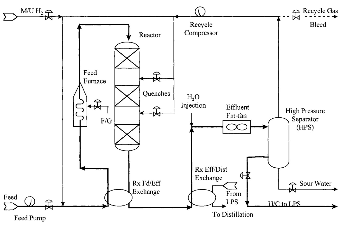
Figure 1: Hydrocracker Reaction Section
Temperature Rise Limits for Design and Operation
Hydrocracking reactions are inherently susceptible to temperature excursions/runaways because of the catalysts and reactions involved in the process. As a result, attention must be given to controlling temperature rise in each catalyst bed to a manageable level. Thus, designers will typically set limits during design phase on the maximum allowable temperature rise in a catalyst bed, which will depend on the catalyst used in that bed. It is typical to set higher limits on allowable rise in hydrotreating catalyst beds, since pretreat catalyst is inherently more stable than hydrocracking catalyst. For beds containing cracking catalyst, lower maximums are set which will depend on the activity of the catalyst used.
For operating units, refiners can get recommended maximum allowable rises for operation from their licensor and or catalyst supplier.
Catalyst Bed Sizing – Heat Release Considerations
With limits established on catalyst bed temperature rise, the catalyst beds can be sized to stay within those limits based on the reactivity of the feedstock. This can vary widely depending on the feed source. Feeds containing cracked stocks will generally limit bed size to much lower volumes than straight run feeds. This is especially true for the lead bed in a pretreat system processing coker gas oils, as the heat release associated with olefin saturation is roughly double that associated with aromatics saturation or desulfurization and olefin saturation will largely be completed in the first catalyst bed.
For operating units, refiners may be limited on the amount of cracked stock that can be processed due to existing catalyst bed sizes. Options for dealing with this situation may include short loading the catalyst bed, using very low activity demet catalyst to fill catalyst bed volume, lowering operating temperature and going to an ascending temperature profile to spread the heat release over more catalyst beds to keep the reaction rate stable, or a combination of these.
Another issue confronting refiners is the use of newer, more active, zeolitic catalysts in older reactors that were designed for lower activity all-amorphous catalyst systems. These older reactors tend to have deep catalyst beds that make temperature control difficult for more active catalyst systems. Chevron’s own refineries have dealt with this issue by going to co-extrudate catalyst systems with combined hydrotreating/hydrocracking functions to uniformly distribute the temperature rise across the entire bed. Alternatively, stacking a more active cracking catalyst on top of a hydrotreating catalyst will maintain stable temperature control across the cracking portion and further improve product quality across the hydrotreating layer.
Reactor Diameter – Hydraulic Considerations
During design, reactor diameter will be set by hydraulic pressure drop or mass flux targets. Each licensor will have their own criteria for setting these targets, since the reactor(s) is the single largest component in the high-pressure loop.
It is not uncommon to see refiners operating their units at feed rates as high as 50% over the original design with the original reactors in place. This is made possible by a combination of factors including:
-
conservative (lower) targets on mass flux in the original design
-
reduced gas-to-oil ratio.
-
the use of larger size catalyst
-
sock loading catalyst beds for reduced pressure drop where necessary.
-
lowering the high-pressure separator pressure to accommodate existing charge pump head.
Typically, all of the above will be used on hydrocrackers in which unit capacity is much higher than the original design.
It should be noted also that new reactor internals, in addition to offering better design to simplify assembly and disassembly, can provide the refinery with access to more catalyst within the existing catalyst volume. Depending on the severity of maldistribution in the catalyst bed, it is not unusual to gain access to 10-20% more catalyst in an existing catalyst bed by virtue of the improved vapor and liquid distribution modern internals can offer.
JOHN KULACH and RICHARD HOEHN (UOP)
-
Reactor diameter is calculated based on reactor charge and mass flux. Flux is defined as the mass flow per unit area per time. Licensors may define flux in several ways, criteria and design methods. For example, liquid mass flow can be used or liquid flus plus vapor may be considered in the overall flux calculation. In choosing the proper mass flux to use, consideration should be given to its effect on the flow distribution in the reactor bed, particularly for 2 phase flow and the resulting pressure drop as the material flows through the catalyst bed. Larger mass fluxes give higher pressure catalyst bed pressure drop, but also result in lower reactor weight and therefore cost for the same space velocity, resulting in economic tradeoff.
-
Reactor Metallurgy is selected based on two criteria: (1) the need to resist hydrogen attack and (2) the need to resist sulfur attack, either from hydrogen sulfide or organic sulfur in the feed components. For hydrogen attack resistance, API 941 (Nelson Curve) is used to determine the base metal. Typical materials used are 1 or 1-1/4 Cr, ½ Mo steel or 2-1/4, 1 Mo steel according to the hydrogen partial pressure at the design pressure and temperature of the reactor. The wall thickness of the reactor will be determined by the properties of the selected material at the required design temperature and pressure. Additionally, to provide resistance to attack either by hydrogen sulfide or organic sulfur, a lining is usually applied, typically consisting of 1/8” (3 mm) of TP321 or T347 SS. The internals, such as distribution trays, quench zone components, inlet and outlet collectors and thermometry components will also be fabricated of SS. For feeds having a high TAN, TP 317SS would be used instead of TP321 or TP 347 for the lining and internals.
-
Bed length and number of beds are determined by many factors such as operating severity, catalyst choice and reactor weight. The ideal philosophy is to strike a balance to maximizing catalyst cycle length and capitol cost of the reactor. Maximizing cycle length implies maximum usage of the catalyst from a perspective of axial temperature rise. Hydroprocessing reactors will have a maximum metallurgical temperature limitation, based on the metallurgy employed for reactor fabrication. Therefore, infinite catalyst beds operating at a constant bed temperature will limit approach to the reactor metallurgical temperature limit. However, due to reactor fabrication cost and heat integration, this approach is not practically feasible. Reasonable criteria is then used for number of beds utilized in the design with the design intent to limit axial rise in a catalyst bed. The criteria for hydrotreating catalyst are different than that used for hydrocracking catalyst. There are different criteria for the various types of hydrocracking catalyst based on activity. These criteria are set up to allow for unit operability and to prevent potential for temperature excursion.
-
Finally, there is a practical limit to the maximum bed length. The catalyst bed itself does not usually do much re-distribution, particularly at low flux rates. So very long beds tend to suffer from poor distribution especially at the bottom of the bed. Since the highest bed temperatures occur at the bottom of the bed, this can contribute to hot spots leading to coke ball formation or temperature runaways.
-
Feed type impacts bed length depending on the types of compounds in the feed. Certain compounds react quickly and have higher heat of reactor than others (olefins > aromatics > naphtenes). Highly exothermic feeds typically require shorter beds and more of them.
-
Operating pressure is usually a function of desired product quality and required cycle length. The choice of operating pressure will impact reactor wall thickness and therefore reactor weight. Reactor weight can limit size of reactor tangent – therefore requiring a second or third reactor. Operating pressure also influences degree of feed saturation, which is a highly exothermic reaction.
-
Desired product yield, product properties, and cycle length impacts reactor sizing. Desired product yield will determine choice of catalyst based on its selectivity to the product slate. Catalyst choice and operating pressure will determine the product properties. The choice of the catalyst will then come with its inherent activity and determine volume requirements for cycle length to provide adequate temperature cycle (SOR temperature to EOR temperature).
-
Unit design flow scheme can impact reactor size and is dependent on feed rate, feed contaminants, conversion requirements, and product requirements. The choice of flow scheme (Once Through, Single Stage Recycle, Two Stage) can shift operating severity and increase catalyst performance. A two-stage unit can decrease catalyst volume requirement although more reactors may be needed, whereas the same product requirements in once through operation might require maximum catalyst volume and therefore influence bed lengths and the number of catalyst beds.