Question 17: What minimum nozzle velocities are required in air and steam distributors to prevent catalyst backflow and subsequent erosion? Please consider both upward and downward pointing nozzles.
HEATER (BASF Catalysts)
The FCC has many distributors: combustion air, stripping steam, feed nozzles, and torch oil. Many routine FCC problems are the result of poor distributor operation; for example, poor yields due to poor catalyst/oil contact, poor stripping due to lack of catalyst/steam contact, and excessive attrition due to distributor damage.
Common points of nozzle design:
- Standard dual diameter nozzles: You have an orifice controlling the pressure drop to ensure even distribution and no catalyst backflow and a nozzle diameter setting an acceptable outlet velocity.
- You need a sufficient distance from the orifice to the nozzle, such as if there is fully developed flow in the nozzle before it exits.
- You need sufficient cover of the process area to ensure good vapor/catalyst contact. This can be done in two different ways. You can have a large number of nozzles; that is, one square foot per process area. Or, you can have nozzles with high outlet velocity to rely on jet penetration.
Typical distributor and nozzle design includes the following:
- Orifices sized to give pressure drop equal to 30% of static height above the distributor,
- Nozzle outlet velocity of 90 fps to 100 fps,
- Minimum nozzle length of 5.2 times the difference between the nozzle diameter and the orifice diameter (engineering firms tend to use 1.5 to 3), and
- Drains to allow wet media to discharge freely.
To prevent catalyst backflow into nozzles, there are two answers. For a single nozzle, industry standard is to maintain 25 fps velocity in the orifice area. That seems like a low velocity, but that should keep the nozzle clear. For a distributor, the parameter is minimum pressure drop. The guideline is 10% to 30% of static bed height. Commonly, this is 10% for downward facing nozzles and 30% for upward facing nozzles.
The most likely mechanism for catalyst backflow is the sudden loss of pressure of the flowing media, resulting in instantaneous backflow. This may require waiting until the next downtown to unplug the distributor. Any distributor can experience backflow and plugging if the flow gets sufficiently low.
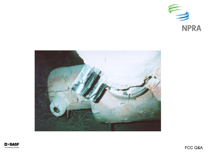
This is a picture of an air grid where there is severe erosion on the nozzles in front due to the addition of the catalyst.
THOMPSON (Chevron)
We generally focus on nozzle pressure drop rather than velocity as a key criteria for the nozzle design. We limit nozzle velocities to maximum 250 fps and prefer velocities below 200 fps. Recently, design distributors have been designed with air velocities of 80 fps to 100 fps. We follow the industry criteria of 30% of the bed pressure drop for upward pointing nozzles and 10% of the bed pressure drop for downward pointing nozzles.
REZA SADEGHBEIGI (RMS Engineering)
Ralph brought up a good point for designing these nozzles: that it has to have a decent pressure drop. However, one thing you need to keep in mind is that sometimes the engineer who designed this put in his calculation, which comes out to be 1/8 of an inch orifice. You have to use common sense because you can design for four pounds or five pounds or 2 pounds psi. If the hole turned out to be too small, which has happened in many cases, you will plug up that nozzle orifice very quickly. So there should be a minimum requirement on the design of the orifice when you design this distributor because otherwise the catalyst can easily block that orifice and plug the nozzle.
The other thing that you have to think about is: Can the distributor absorb shocks? The support of that distributor is very important because you are never going to have dry catalyst every day, day in and day out. You are going to have water. So if you are going to have a wet catalyst, how is the distributor going to be able to handle that? In the last two years, we have designed four steam distributors that have been installed with great success. These are some of the things that you need to keep in mind, rather than all those velocities and ΔPs.
Mechanical designs: You know, they show you through factory lines so that nozzle velocity is low. Therefore, the attrition rate is—The other thing is that I see in our industry is that lack of communication between a designer and a refiner. Usually, the designer goes to the distributor and they think that, “Oh. Two pound per thousand is good or three pound per thousand.” They put it in and they want to raise the stripping stream because they see that when they increase the stripping stream, the bed temperature goes down. But unfortunately, the stripper was not designed for that. So guess what happens? Attrition goes up. A lot of times, I see that these distributors do not have that flexibility in them. If you design for 5000, can you really go to 10,000 if you needed that?
The other thing is that during startup, especially in a steam distributor, I recommend that you have a provision: If you have a wet steam, put some nitrogen in there. Automatically, nitrogen will come on if you lose the pressure. Or better than that, have a minimum flow around your control valve all the time. Put an orifice in there. That way, if you lost a control valve, you always have minimum amount of stream going through that, which would not plug it. A lot of these problem happen during outages. You lost the power. You come back up—or have attrition. You go to a pressure server; it is partially plugged. They follow all that design criteria. So those are some of the things that you really need to talk to your designer, or whoever it is, to make sure that you have a nice package.
ZIAD JAWAD (Shaw Stone & Webster)
I would agree that different distributor designs may have different criteria. One thing to keep in mind is designs where there is a dampening effect in the bed; for example, in a Model 2 where there is an overflow well and the bottom of the bed does not have fluidized catalyst. You would experience a dampening effect and there may be a difference in the design criteria between different technologies. But in other designs, for example in a reactor where spent catalyst is exiting through the bottom of the bed and the catalyst is fully fluidized above and below the ring, there is less of a difference in the criteria.